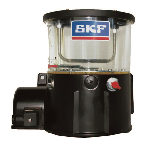
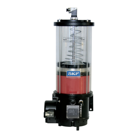
SKF FF Series User manual

EN
FF and FB
Multiline pump units
for use in progressive centralized lubrication systems
Assembly instructions
acc. to EC Dir. 2006/42/EC for partly completed machinery with
associated operating instructions
Version 03

Page 2
EN
Multiline pump units in the series FF and FB
Notes
Imprint
These original assembly instructions with
associated operating instructions in accor-
dance with EC Machinery Directive 2006/42/
EC are an integral part of the described prod-
uct and must be kept for future use.
These original assembly instructions with as-
sociated operating instructions have been pre-
pared in accordance with the established stan-
dards and rules for technical documentation,
VDI 4500 and EN 292.
© SKF Lubrication Systems Germany AG
This documentation is protected by copyright.
SKF Lubrication Systems Germany AG re-
serves all rights, including those to the photo-
mechanical reproduction, duplication, and dis-
tribution by means of special procedures (e.g.,
data processing, data media, and data net-
works) of this documentation in whole or in
part.
Subject to changes in contents and technical
information.
Service
If you have technical questions, please contact
the following addresses:
SKF Lubrication Systems Germany AG
Berlin Plant
Motzener Strasse 35/37
12277 Berlin
Germany
Tel. +49 (0)30 72002-0
Fax +49 (0)30 72002-111
www.skf.com/lubrication
Hockenheim Plant
2. Industriestrasse 4
68766 Hockenheim
Germany
Tel. +49 (0)62 05 27-0
Fax +49 (0)62 05 27-101
www.skf.com/lubrication

Page 3 EN
Table of contents
Operating instructions 31
1. Safety instructions 32
2. Lubricants 32
3. Transport, delivery, and storage 33
3.1 Lubrication units 33
3.2 Electronic and electrical devices 33
3.3 General notes 33
4. Assembly 34
4.1 Information on assembly 34
4.2 Assembly of the FF and FB pump
unit 34
4.3 Dismantling and disposal 34
5. Design and function 35
5.1 Pump operation 35
5.2 Pump element operation 36
5.3 Designs 37
6. Commissioning 38
6.1 Commissioning and recommissioning 38
6.2 Varying pump displacement 40
6.3 Conguration of ultrasonic sensor 42
7. Shutdown 43
7.1 Temporary shutdown 43
7.2 Permanent shutdown 43
8. Maintenance 44
8.1 General information 45
8.2 Visual inspection 46
8.3 Removing a pump element 47
8.3.1 Fitting mandrel accessory 47
8.4 Installing a pump element 48
8.4.1 Tightening torques for pump elements
48
9. Malfunctions 49
9.1 Commissioning malfunctions 50
9.2 Operational malfunctions 51
9.3 Malfunctions on ll level control 53
9.4. Malfunctions on U2 ultrasonic sensor 54
10. Technical data 55
FF multiline pump unit 55
FB multiline pump unit 56
Table of contents
Assembly instructions
Information concerning EC Declaration of Confor-
mity and EC Declaration of Incorporation 4
Explanation of symbols and signs 5
1. Safety instructions 7
2. Lubricants 10
3. Overview 12
4. Assembly 13
4.1 Setup and attachment 13
4.1.1 Assembly of FF and FB pump unit 14
4.2 Connecting dimensions 16
4.2.1 FF assembly drawing 16
4.2.2 FF Minimum installation clearance 17
4.2.3 FF Assembly holes 17
4.2.4 FB Assembly drawing 18
4.2.5 FB Minimum installation clearance 19
4.2.6 FB Assembly holes 19
4.3 Electrical motor connection 20
4.3.1 FF Motor ratings 21
4.3.2 FB Motor ratings 1M and 2M 22
4.3.3 Assembly of the electric ll level switch 23
4.4 Compressed air line connection 27
4.5 Hydraulic line connection 27
4.6 Lubrication line connection 27
4.6.1 Assembly of the lubrication lines 27
4.7 Lubrication line arrangement 28
4.8 Note on the rating plate 29

Page 4
EN
The product,
Multiline pump unit
of the series: FF and FB
is hereby confirmed to comply with the essen-
tial protection requirements stipulated by the
Directive(s) of the Council on the approxima-
tion of laws of the Member States concerning:
Machinery directive 2006/42/EC
Low voltage devices 2006/95/EC
Electromagnetic compatibility
2004/108/EC
...
Notes:
(a) This declaration certifies compliance with
the aforementioned Directives, but does
not constitute a guarantee of
characteristics.
(b) The safety instructions in the documenta-
tion included with the product must be
observed.
(c) The commissioning of the products here
is prohibited until such time as the ma-
chine, vehicle or other device in which the
Information concerning EC Declaration of Conformity and EC Declaration of Incorporation
product is installed conforms with the pro-
visionsand requirements of the applicable
Directives.
(d) The operation of the products at non-
standard supply voltage, as well as
non-adherence to the installation in-
structions, can negatively impact the
EMC characteristics and electrical
safety.
We further declare:
The aforementioned product is, according
to EC Machinery Directive 2006/42/EC,
Annex II Part B, designed for installation in
machinery / for incorporation with other
machinery to form a machine. Within the
scope of application of the EC Directive,
commissioning shall be prohibited until the
machinery in which this part is installed
conforms with the provisions of this
Directive.
The aforementioned product may, with
reference to EC Directive 97/23/EC con-
cerning pressure equipment, only be used
in accordance with its intended use and in
conformity with the instructions provided
in the documentation. The following must
be observed in this connection:
The product is neither designed nor ap-
proved for use in conjunction with fluids of
Group 1 (Dangerous Fluids) as defined in
Article 2, Para. 2 of Directive 67/548/EEC
of June 27, 1967. The product is neither
designed nor approved for use in conjunc-
tion with gases, liquefied gases, pressur-
ized gases in solution, vapors and such
fluids whose vapor pressure exceeds nor-
mal atmospheric pressure (1013 mbar) by
more than 0.5 bar at their maximum per-
missible temperature.
When used in conformity with their in-
tended use, the products supplied by SKF
Lubrication Systems Germany AG do not
reach the limit values listed in Article 3,
Para. 1, Clauses 1.1 to 1.3 and Para. 2 of
Directive 97/23/EC. They are therefore not
subject to the requirements of Annex 1 of
the Directive. Consequently, they do not
bear a CE marking in respect of Directive
97/23/EC. SKF Lubrication Systems
Germany AG classifies them according to
Article 3, Para. 3 of the Directive.
The Declaration of Conformity and
Incorporation forms part of the product
documentation and is supplied together
with the product.
Information concerning EC Declaration of Conformity and EC Declaration of Incorporation

Page 5 EN
Informational symbols
Indicators used with safety instructions
and their meaning
Hazard symbols
Explanation of symbols
Explanation of symbols and signs
You will nd these symbols, which warn of
specic dangers to persons, material assets, or
the environment, next to all safety instructions
in these operating instructions.
Please heed these instructions and proceed
with special care in such cases. Please forward
all safety instructions to other users.
General hazard
DIN 4844-2-W000
Electrical voltage/current
Hot surface
Indicator Use
Danger! danger of bodily injury
Warning! danger of damage to prop-
erty and the environment
Note! provides additional informa-
tion
Note
Prompts an action
Used for itemizing
Points out other facts,
causes, or consequences
Provides additional information
Instructions placed directly on the machines/
grease lubrication pump units, such as:
Arrow indicators
Labels for uid connections
must be followed and kept in fully legible
condition.
You are responsible!
Please read the assembly and operating
instructions thoroughly and follow the safety
instructions.
Danger of being drawn into machinery
DIN 4844-2-W008
DIN 4844-2-W026
BGV 8A
Slipping hazard
DIN 4844-2-W028
Warning of potentially explosive
atmosphere
DIN 4844-2-W021

Page 6
EN Assembly instructions
Assembly instructions in
accordance with Machinery
Directive 2006/42/EC,
Annex VI
The assembly instructions fulfill the Machinery
Directive indicated above with regard to partly
completed machinery. Partly completed ma-
chinery, which includes the product described
herein, is only intended to be incorporated into
or assembled with other machinery or other
partly completed machinery or equipment,
thereby forming machinery to which the
above-mentioned Directive applies.

Page 7 EN
Assembly instructions
1. Safety instructions
The operator of the described product
must ensure that the assembly instruc-
tions are read and understood by all
persons assigned with the assembly,
operation, maintenance, and repair of
the product. The assembly instructions
must be kept ready to hand.
Note that the assembly instructions
form part of the product and must
accompany the product if sold to a new
owner.
In addition to the assembly instructions,
general statutory regulations and other
regulations for accident prevention
and environmental protection must be
observed and applied.
1.2 Authorized personnel
Only qualified technical personnel may install,
operate, maintain, and repair the products de-
scribed in the assembly instructions. Qualified
technical personnel are persons who have
been trained, assigned and instructed by the
operator of the final product into which the
described product is incorporated. Such per-
sons are familiar with the relevant standards,
rules, accident prevention regulations, and as-
sembly conditions as a result of their training,
experience, and instruction. They are autho-
rized to identify and perform necessary ac-
tions while avoiding any risks which may arise.
The definition of qualified personnel and the
prohibition against employing non-qualified
personnel are laid down in DIN VDE 0105 and
IEC 364.
The described product is manufactured in ac-
cordance with the generally accepted rules and
standards of industry practice and with occu-
pational safety and accident prevention regu-
lations. Risks may, however, arise from its us-
age and may result in physical harm to
persons or damage to other material assets.
Therefore the product may only be used in
proper technical condition and in observance
of the assembly instructions. In particular, any
malfunctions which may affect safety must be
remedied immediately.
1.1 Intended use
Pump units of SKF's FF and FB series are
used to supply centralized lubrication systems
in vehicles, systems and machines.
They deliver mineral oils or environmentally
friendly oils from ISO VG 46 and greases up to
NLGI Grade 3. The technical data specifications
in Chapter 10 of the operating instructions
must be adhered to. Only media approved for
these types of pump units may be used.
Unsuitable media may result in pump unit fail-
ure and potentially severe bodily injury and
property damage. The use of synthetic and
biodegradable oils or greases requires prior
approval from SKF Lubrication Systems
Germany AG.
Any other usage is deemed non-compliant
with the intended use.

Page 8
EN Assembly instructions
1.4 System pressure hazard
Lubrication systems are pressurized
during operation. Centralized lubri-
cation systems must therefore be
depressurized before starting assembly,
maintenance or repair work, or any
system modications or system repairs.
1.5 Compressed air hazard
The described product is pressurized
during operation. The product must
therefore be depressurized before
starting
assembly, maintenance or repair work,
or any system modications or system
repairs.
Depending on the model design, the product
may be able to be operated with compressed
air. Through the use of the appropriate com-
pressed air quality class, compressed air prep-
aration can be optimized and machine down-
time and higher maintenance costs avoided.
The compressed air to be used here must
comply with at least quality class 5 as dened
by ISO 8573-1:
1.6 Hydraulic pressure hazard
The described product is pressurized
during operation. The product must
therefore be depressurized before
starting assembly, maintenance or re-
pair work, or any system modications
or system repairs.
Depending on the model design, the product
may be able to be operated hydraulically.
1.3 Electric shock hazard
Electrical connections for the described prod-
uct may only be established by qualified and
trained personnel authorized to do so by the
operator, and in observance of the local condi-
tions for connections and local regulations
(e.g., DIN, VDE). Significant bodily injury and
property damage may result from improperly
connected products.
Danger!
Work on products that have not been
de-energized may result in bodily
injury.
Assembly, maintenance and repair work
may only be performed on products
that have been de-energized by
qualied technical personnel. The
supply voltage must be switched off
before opening any of the product's
components.
Max. particle size 40 μm
Max. particle density 10mg/m³
Pressure dew point 7°C
Water content max. 7800 mg/ m³
Residual oil content max. 25 mg/ m³

Page 9 EN
Assembly instructions
1.7 Explosion protection information
Danger!
Only the pump models tested and
approved by SKF Lubrication Systems
Germany AG in accordance with ATEX
Directive 94/9/EC are permitted to be
used in areas with explosion protec-
tion. The relevant class of protection is
engraved on the pump's rating plate.
When lling lubricant into the pump,
make sure the lubricant is clean. The
reservoir
must be lled in good time (pay attention
to ll level monitoring). Lubricant must be
lled only via the ller socket G 3/8“ (FF)
or G 1/2“ (FB) on the pump ange. Lubri-
cant may only be lled via the "reservoir
lid" if absolutely certain that no potentially
explosive atmosphere exists.
In the case of overlling, the excessive
amount of lubricant must be removed.
Make sure there is no potentially explo-
sive atmosphere when doing this.
The switching circuits of the ll level
monitor
must be supplied by an intrinsically safe
circuit, e.g. through the installation of an
ATEX-compliant isolating switch by the
customer.
The unit must be grounded via a ground
connection. The customer must install
adequate overload protection for the
power consumption of the motor.
To avoid electrostatic discharge, lay
hydraulic connecting lines in corrosion-
resistant metal tubing, e.g. stainless steel
pipe.
When setting up the pump make sure the
setup location is even so that the unit will
not shudder.
During maintenance work, use only tools
intended for use in potentially explosive
spaces or else make certain that there is
no potentially explosive atmosphere
present.
The service life of the grease lubrication
pump is limited. It must therefore un-
dergo a function and leak test at regular
intervals. Perform appropriate repairs in
the event of malfunctions, leaks, or rust.
Replace the pump if necessary.
The user must make sure through the
choice of the lubricant to be delivered that
no chemical reactions capable of serving
as ignition sources will occur in conjunc-
tion with the explosive atmospheres
expected.
The lubricant’s ignition temperature has
to be at least 50 kelvins above the pump’s
maximum surface temperature (tempera-
ture class).

Page 10
EN Assembly instructions
2. Lubricants
2.1 General information
All products from SKF Lubrication
Systems Germany AG may be used
only for their intended purpose and in
accordance with the information in the
product's assembly instructions.
Intended use is the use of the products for the
purpose of providing centralized lubrication/
lubrication of bearings and friction points us-
ing lubricants within the physical usage limits
which can be found in the documentation for
the devices, e.g. assembly instructions/operat-
ing instructions and the product descriptions,
e.g. technical drawings and catalogs.
Particular attention is called to the fact that
hazardous materials of any kind, especially the
materials classified as hazardous by EC
Directive 67/548/EEC, Article 2, Para. 2, may
only be filled into SKF centralized lubrication
systems and components and delivered and/or
distributed with the same after consultation
with and written approval from SKF
Lubrication Systems Germany AG. No
products manufactured by SKF Lubrication
Systems Germany AG are approved for use in
conjunction with gases, liquefied gases, pres-
surized gases in solution, vapors, or such flu-
ids whose vapor pressure exceeds normal at-
mospheric pressure (1013 mbar) by more
than 0.5 bar at their maximum permissible
temperature.
Other media which are neither lubricant nor
hazardous substance may only be fed into the
products after consultation and written ap-
proval from SKF Lubrication Systems Germany
AG.
SKF Lubrication Systems Germany AG consid-
ers lubricants to be an element of system de-
sign which must always be factored into the
selection of components and the design of
centralized lubrication systems. The lubricating
properties of the lubricants are critically im-
portant in these considerations.
2.2 Selection of lubricants
Observe the instructions from the
machine manufacturer regarding the
lubricants that are to be used.
Warning!
The amount of lubricant required at
a lubrication point is specied by the
bearing or machine manufacturer. It
must be ensured that the required
quantity of lubricant is provided to the
lubrication point. The lubrication point
may otherwise not receive adequate
lubrication, which can lead to damage
and failure of the bearing.
Selection of a lubricant suitable for the lubri-
cation task is made by the machine/system
manufacturer and/or the operator of the ma-
chine/system in cooperation with the lubricant
supplier.
The bearings/friction points that require lubri-
cation, their expected load during operation,
and the expected ambient conditions are taken
into account during selection, with consider-
ation of economic and environmental aspects.

Page 11 EN
Assembly instructions
2.4 Lubricants and the environment
Lubricants can contaminate soil and
bodies of water. Lubricants must be
properly used and disposed of. Observe
the local regulations and laws regarding
the disposal of lubricants.
It is important to note that lubricants are envi-
ronmentally hazardous, flammable substances
which require special precautionary measures
during transport, storage, and processing.
SKF Lubrication Systems Germany AG
Systems Germany AG supports cus-
tomers
in the selection of suitable components
for feeding the selected lubricant and in
the planning and design of a
centralized lubrication system.
Please contact SKF Lubrication Systems
Germany AG if you have further questions re-
garding lubricants. It is possible for lubricants
to be tested in the company's laboratory for
their suitability for pumping in centralized lu-
brication systems (e.g. "bleeding").
You can request an overview of the lubricant
tests offered by SKF Lubrication Systems
Germany AG from the company's Service
department.
2.3 Approved lubricants
Only lubricants approved for the prod-
uct may be used. Unsuitable lubricants
can lead to failure of the product and to
property damage.
Different lubricants cannot be mixed, as
mixing may result in damage and ne-
cessitate costly and complicated clean-
ing of the product/lubrication system.
It is recommended that an indication of
the lubricant in use be attached to the
lubricant reservoir in order to prevent
accidental mixing of lubricants.
The product described here can be operated
using lubricants that meet the specifications in
the technical data. Depending on the product
design, these lubricants may be oils, fluid
greases, or greases.
Oils and base oils may be mineral, synthetic,
and/or rapidly biodegradable. Consistency
agents and additives may be added depending
on the operating conditions.
Note that in rare cases, there may be lubri-
cants whose properties are within permissible
limit values but whose other characteristics
render them unsuitable for use in centralized
lubrication systems. For example, synthetic lu-
bricants may be incompatible with elastomers.

Page 12
EN Assembly instructions
Fig. 1 Components of the FF and FB units
3. Overview
Components of the unit
Item Description
1 Fill level control/fill level switch
Ultrasonic sensor
2 Lubricant reservoir
3 Pump element with ring connection
4 Pump motor with electrical connection
5 Filler socket
Consult the safety data sheet from the lubri-
cant manufacturer for information regarding
transport, storage, processing, and environ-
mental hazards of the lubricant that will be
used.
The safety data sheet for a lubricant can be
requested from the lubricant manufacturer.
2.5 Lubricant hazards
Centralized lubrication systems must
always be free of leaks. Leaking lu-
bricant is hazardous due to the risk of
slipping and injury. Be mindful of any
lubricant leaking out during assembly,
operation, maintenance, and repair of
centralized lubrication systems. Leaks
must be sealed off without delay.
Lubricant leaking from centralized lubrication
systems is a serious hazard. Leaking lubricant
can create risks that may result in physical
harm to persons or damage to other material
assets.
Follow the safety instructions on the
lubricant's safety data sheet.
Lubricants are a hazardous substance. The
safety instructions on the lubricant's safety
data sheet must be followed. The safety data
sheet for a lubricant can be requested from
the lubricant manufacturer.
1
2
3
5
4
FB
FF 4

Page 13 EN
Assembly instructions
4. Assembly
4.1 Setup and attachment
The product should be protected from humid-
ity and vibration, and should be mounted so
that it is easily accessible, allowing all further
installation work to be done without difficulty.
Make sure there is adequate air circulation to
prevent the product from overheating. For the
maximum permissible ambient temperature,
see "Technical data."
The mounting position of the product is verti-
cal as shown in the assembly drawing.
Pressure gauges, oil level glasses, temperature
gauges, and other visual monitoring equip-
ment must be easy to see.
During assembly and especially when drilling,
always pay attention to the following:
Existing supply lines must not be dam-
aged by assembly work.
Other units must not be damaged by as-
sembly work.
The product must not be installed within
range of moving parts.
The product must be installed at an ad-
equate distance from sources of heat.
Maintain safety clearances and comply
with local regulations for assembly and
accident prevention.

Page 14
EN Assembly instructions
The FF and FB multiline pump units must be
installed on a level surface. The pump's base
plate must not be under stress. Sufficient
space must be provided during installation for
later service and maintenance work (see pages
13 and 15).
When the reservoir is empty and its lid is re-
moved, the agitator of the lubrication pump
should be visible, so that the functioning and
direction of rotation of the pump can be
checked by switching the pump on briey.
In the case of pumps with electrical grease-
or oil level monitoring, the clearance required
above the pump can be up to 400 mm, de-
pending on the height of the reservoir. The in-
stalled pump elements are set for full stroke,
with the ring pieces with the check valve (1)
pointing upwards. The cap nut (WAF 24) (2)
keeps the ring piece pressed against the screw
socket (3). If you want to point the ring piece
in a different direction, loosen the cap nut and
tighten it again with given Torgue, see Operat-
ing instructions, Fig. 8.4.1.
The number of pump elements can also be
changed later. The pump has to be shut done
4.1.1 Assembly of FF and FB pump unit
while this is done - see the maintenance
chapter in the operating instructions. Internal
treads for installing pump elements have to be
sealed off with screw plugs M 20 x 1.5 (see
accessories, page 53) if not in use.
Fig. 2 Pump units sectional view
Item Description
1 Ring piece with check valve
2 Cap nut
3 Screw socket
4 Lubrication line connection
1
2
4
Warning!
Pump elements must not be connected
to the connection for the lubrication
line (4).
3

Page 15 EN
Assembly instructions
Warning!
When drilling the assembly holes, you
must be careful of any supply lines or
other units, as well as of other hazards
such as
moving parts.
Maintain safety clearances and comply
with local regulations for assembly and
accident prevention.
Warning!
Do not tilt or drop the FF or FB multi-
line pump unit!
Danger!
The reservoir cover must be installed
before turning on or commissioning
the FF and FB multiline pump units.
The agitator may cause injury if the
reservoir cover is not installed.
The multiline pump units are installed using 3
screws (and washers). If M10 tapped bores
are used to fasten the unit, the screws must
have a minimum length of 20 mm.
Fastening material to be provided by the
customer:
Hexagon head screws (3x) acc. to
DIN933-M10x20-8.8
Washers (4x) acc. to DIN 125-B10.5-St
Drill assembly holes (M10) acc. to assembly
drawing (Fig. 2) and the conditions on the
surface.
Clean surface to remove drilling chips.
Place the pump unit on the surface and
roughly align it.
Pass hexagon head screws (3x) acc. to
(DIN933-M10x20-8.8) with associated
washers (4x) acc. to DIN 125-B10.5-St
through the xing holes on the pump
baseplate and apply the screws to the M10
threads on the surface.
Gently tighten hexagon head screws (3x).
Align pump unit, tighten hexagon head
screws with following torque:
Torque 50 Nm

Page 16
EN Assembly instructions
Fig. 3 FF Multiline pump unit 1M and 2M
4.2 Connecting dimensions
4.2.1 FF assembly drawing
38°
10
11
12
1
234
5
6
7
8
9
125
160
11
30
17
36
80
175
ø163
650 (10kg)
450 (4kg)
ø208
110
~250~250
80
°
38°
10
11
12
1
234
5
6
7
8
181
456 (4 kg)
656 (10kg)
ø208
ø163
80
~250
160
11
30
17
80
36
°
Filler socket G 3/8"
Position of pump elements
Filler socket G 3/8"
Position of pump elements
Type 1M Type 2M

Page 17 EN
Assembly instructions
Minimum installation clearance
FF/4 kg FF/10 kg
[cm] [cm]
U2 ultrasonic sensor 55 75
Fill level control G 68 115 Fill level
control S 70 90
Fill level switch E 70 110 Fill level
switch F 75 115 Fill level
switch H 80 120
Fill level switch A 80 125
Fill level switch W 60 85
Fig. 4 FF Multiline pump unit, assembly holes 1M and 2M
FF..2M
FF..1M
120
138.60
69.30
Ø 11
138.60
69.30
Ø 11
120
4.2.3 FF Assembly holes4.2.2 FF Minimum installation clearance
40.00
40.00

Page 18
EN Assembly instructions
Fig. 5 FB Multiline pump unit 1M and 2M
4.2.4 FB Assembly drawing
190
30°
11
236
82
Ø210
50
~ 310
130
113
80
Ø 318
Ø 205
approx 660 (15 kg)
approx. 650 (30 kg)
approx 420 (6 kg)
15
14°
24
36
max.24
Pump elements
2. row 13 - 24
Pump element
10
22
9
21 8
20 7
19 618
517
416
3
15
2
14
1
13
11 12
23
24
1. row 1 - 12
Filler socket G 1/2”
113 24
15
190
30°
11
236
Ø205
82
Ø210
~ 260
50
~ 430
36
80
130
max. 24
pump elements
approx. 420 (6kg Reservoir)
approx. 660 (15kg Reservoir)
2. row 13 - 24
1. row 1 - 12
Pump elements
23
11
24
10
22 921
820
719
6
18
5
17
4
16
3
15
2
14
1
13
14°
Filler socket G 1/2”
113 24
15
Ø318
236
Ø205
82
Ø210
approx. 420 (6 kg)
approx. 650 (30 kg)
approx. 660 (15 kg)
36
80
130
50
11
30°
~ 415
25
max. 24
pump element
2. row 13 - 24
1. row 1 - 12
1
2
3
4
5
6
7
8
9
10
11 12
13
14
15
16
17
18
19
20
21
22
23
24
14°
Pump element
Type 1M, drive
position B
Type 1M
Drive position E
Type 2M
Drive position H
Filler socket G1/2"

Page 19 EN
Assembly instructions
Minimum installation clearance
FB/6 kg FB/15 kg FB/30 kg
[cm] [cm] [cm]
U2 ultrasonic sensor 50 80 75
Fill level control G 70 120 110
Fill level control S 70 85 85
Fill level switch E 67 115 100
Fill level switch F 60 115 105
Fill level switch H 75 125 115
Fill level switch A 80 125 120
Fill level switch J - - 130
Fill level switch W 65 100 90
Fig. 6 FB Multiline pump unit, assembly holes 1M and 2M
4.2.6 FB Assembly holes4.2.5 FB Minimum installation clearance
FB..1M..E 204.40
59.00
102.20
177.00
177.00
204.40
102.20
Ø 11
Ø 11
Ø 11
204.40
102.20
FB..2M..H
FB..1M..B
177.00
59.00
59.00

Page 20
EN Assembly instructions
4.3 Electrical motor connection
Connect the pump unit motor according to
the specications on the motor rating plate
and the motor characteristics.
Electric shock hazard
Electrical connections for the product
may only be established by qualied
and trained personnel authorized to do
so by the operator. The local conditions
for connections and local regulations
(e.g., DIN, VDE) must be observed.
Signicant bodily injury and property
damage may result from improperly
connected products.
Warning!
Connect lines in accordance with the
technical specications and the local
conditions for connections and local
regulations (e.g., DIN, VDE).
Consult the motor's rating plate for the elec-
trical characteristics of the motor, such as rat-
ed power, rated voltage, and rated current.
Observe the guidelines in EN 60034-1 (VDE
0530-1) for operation at the limits of the
ranges A (combination of ±5% voltage devia-
tion and ±2% frequency deviation) and B
(combination of ±10% voltage deviation and
+3/-5% frequency deviation). This applies es-
pecially with regard to heating and deviations
in operating parameters from the ratings on
the motor's rating plate. The limits must never
be exceeded.
The available mains voltage (supply
voltage) must be in accordance with the
specications on the rating plate of the
motor or of the electrical components.
Check the fuse protection of the electri-
cal circuit. Use only fuses with the
prescribed amperage, else bodily injury
and property damage may result.
Be sure to connect the motor so as to guaran-
tee a continuously safe electrical connection
(no protruding wire ends); use the assigned
cable end fittings (e.g. cable lugs, wire end
ferrules). Select connecting cables conforming
to DIN VDE 0100 taking into account the rated
current and the conditions of the specific sys-
tem (e.g. ambient temperature, type of routing
etc. in accordance with DIN VDE 0298 or IEC /
EN 60204-1). Details regarding electrical con-
nection of the motor to the power supply, es-
pecially terminal and connector pin assign-
ment, can be taken from the customer's
drawing for the reservoir unit.
Warning!
When establishing electrical connection
of the pump motor, be mindful of the
correct direction of rotation of the mo-
tor.
If the direction of rotation of a motor
is marked on the product by a rotation
arrow, the motor's direction of rotation
must match the arrow.
This manual suits for next models
1
Table of contents
Other SKF Water Pump manuals

SKF
SKF Lincoln FlowMaster II Instruction Manual

SKF
SKF LINCOLN P623S User manual

SKF
SKF P623M Series User manual

SKF
SKF EPUMP User manual

SKF
SKF PAB Series User manual

SKF
SKF 728619 E User manual

SKF
SKF Linkoln Pile Driver III C Series Instruction Manual

SKF
SKF LINCOLN A Series Instruction Manual

SKF
SKF KFG Series User manual

SKF
SKF KFG User manual
Popular Water Pump manuals by other brands

Danfoss
Danfoss ASV-P instructions

Subaru
Subaru PTD 206 Instructions for use

Gude
Gude GFP 5200 Translation of the original instructions

Goulds Pumps
Goulds Pumps VIC Installation, operation and maintenance instructions

Pfeiffer Vacuum
Pfeiffer Vacuum UNO 005 A operating instructions

DP
DP DHC -M Series Installation and operating manual