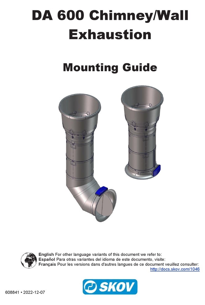
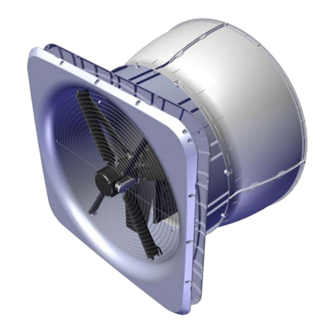
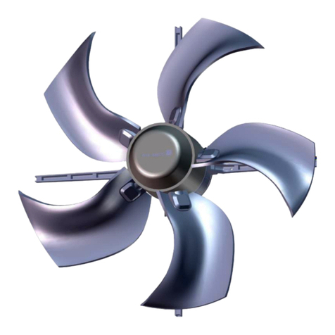
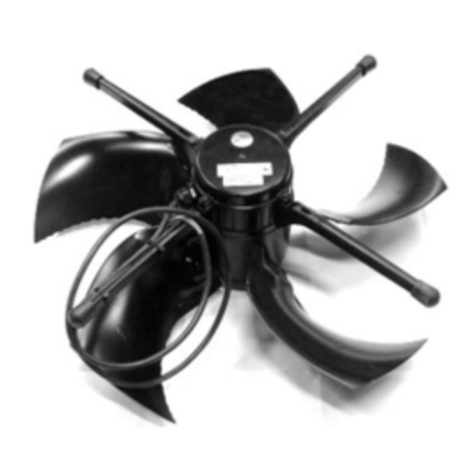
Skov DA 800 LPC Manual


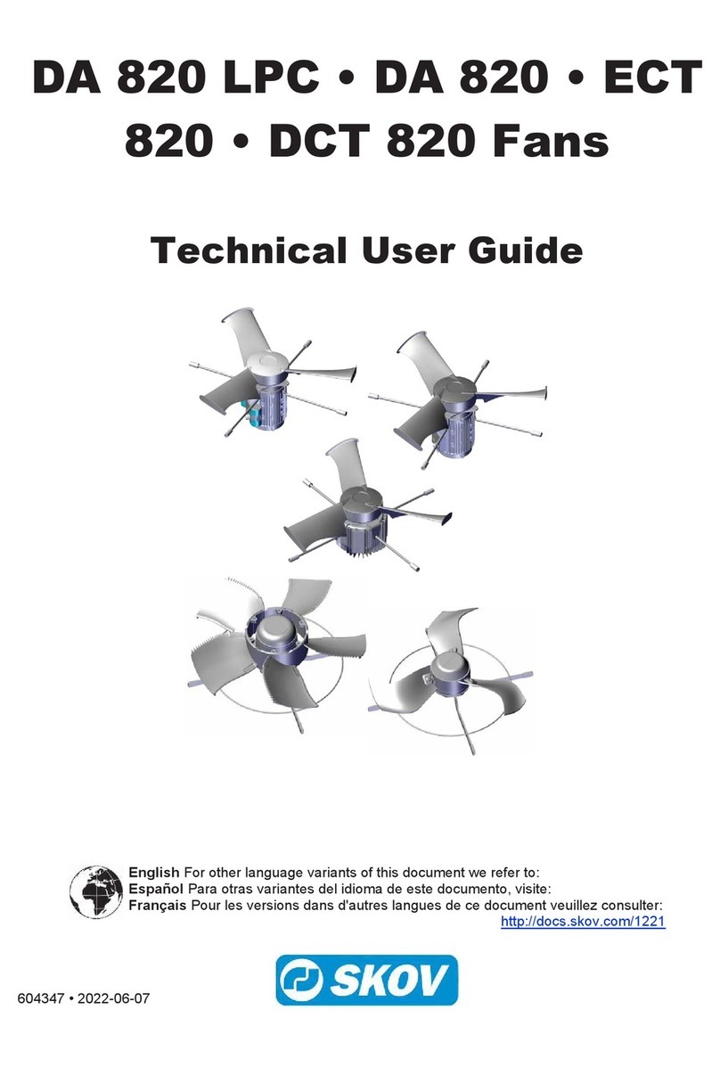
DA 800 LPC
Product and Documentation Changes
SKOV A/S reserves the right to change this manual and the product described herein without further notice. In
case of doubt, please contact SKOV A/S.
The date of change appears on the front and back pages.
IMPORTANT: NOTE CONCERNING ALARM SYSTEMS
When regulating and controlling the climate in livestock buildings, breakdowns, malfunctions or faulty settings
may cause substantial damage and financial losses. It is therefore essential to install a separate, independent
alarm system that monitors the house climate concurrently with the climate and production computer.
According to EU-directive No. 98/58/EU an alarm system must be installed in all mechanically ventilated
houses.
Please note that the product liability clause of general terms and conditions of sale and delivery specifies that an
alarm system must be installed.
In case of an operating error or improper use, ventilation systems can result in production losses or
cause loss of lives among animals.
SKOV A/S recommends that ventilation systems be mounted, operated and serviced only by
trained staff and that a separate emergency opening unit and an alarm system be installed as well as
maintained and tested at regular intervals, according to SKOV A/S’ terms and conditions of sale
and delivery.
Note
•All rights reserved. No part of this manual may be reproduced in any manner whatsoever without the
express written permission from SKOV A/S.
•SKOV A/S has made every effort to ensure the accuracy of the information contained in this manual.
Should any mistakes or imprecise information occur in spite of this, SKOV A/S would appreciate
being notified thereof.
•Irrespective of the above, SKOV A/S shall not have any liability with respect to loss or damage
caused or alleged to be caused by reliance on any information contained herein.
•Copyright 2017 by SKOV A/S.

4 Technical User Guide
DA 800 LPC
1Product Description................................................................................................. 6
1.1 Parts for DA 800 LPC..........................................................................................................6
2General Information................................................................................................. 7
2.1 Recommended Tools..........................................................................................................7
2.2 Warnings and Symbols.......................................................................................................7
3Mounting Guide ....................................................................................................... 8
3.1 Positioning of Fan in the DA 600 Exhaust Unit.................................................................8
3.2 Safety Distance ...................................................................................................................8
3.3 Mounting the Motor Control...............................................................................................9
3.3.1 Position of Motor Controller.....................................................................................................................9
3.3.2 Ensure access and cooling of Motor Controller ......................................................................................9
3.3.3 Positioning of Motor Controller..............................................................................................................10
4Installation Guide....................................................................................................11
4.1 Electrical Connection .......................................................................................................11
4.1.1 Cabling in the Exhaust Unit...................................................................................................................11
4.1.2 Cabling into the Motor Controller ..........................................................................................................11
4.2 Connection in the Motor Controller.................................................................................12
4.2.1 Terminals for Power Supply..................................................................................................................12
4.2.2 Terminals for Power Supply of Fan.......................................................................................................12
4.2.3 Signal Terminals....................................................................................................................................13
4.2.4 Terminals on Relay Module (accessories)............................................................................................13
4.3 DA 800 LPC Fan ................................................................................................................14
4.3.1 Wiring Diagram......................................................................................................................................14
4.3.2 Circuit Diagram......................................................................................................................................15
4.3.2.1 DA 800 LPC...........................................................................................................................................................15
4.4 Dynamic MultiStep............................................................................................................16
4.4.1 Cable chart DA 800 LPC with DA 74CO ON/OFF ................................................................................16
4.4.2 Circuit Diagram ON/OFF.......................................................................................................................17
4.4.2.1 DA 800 LPC with DA 74CO ON/OFF ....................................................................................................................17
4.4.3 Cable Chart DA 800 LPC with DA 74CV Stepless................................................................................18
4.4.4 Circuit diagram Stepless .......................................................................................................................19
4.4.4.1 DA 800 LPC with DA 74CV Stepless.....................................................................................................................19
4.4.5 Cable Chart DA 800 LPC/DA 74CV with Reverse................................................................................20
4.4.6 Circuit diagram DA 800 LPC/DA 74CV with Reverse...........................................................................21
4.4.7 Cable Chart DA 800 LPC/DA 74CV with Alarm Relay..........................................................................22
4.4.8 Circuit diagram DA 800 LPC/DA 74CV with Alarm...............................................................................23
5Setting Fan Voltage In House Computer ..............................................................24
5.1 DOL 234 and DOL 234F before Version 7.2.....................................................................24
5.2 DOL 234F Version 7.2 .......................................................................................................24
5.3 DOL 539 and DOL 534.......................................................................................................24
5.4 DOL 34...............................................................................................................................24
6Maintenance Instructions.......................................................................................25
6.1Cleaning.............................................................................................................................25
6.1.1 Fan ........................................................................................................................................................25

Technical User Guide 5
DA 800 LPC
6.1.2 Motor Controller.....................................................................................................................................25
6.2 Removal for Recycling/Disposal......................................................................................25
7Troubleshooting Guide ..........................................................................................26
7.1 LED indications.................................................................................................................26
8Technical Data ........................................................................................................27
8.1 ErP/Ecodesign...................................................................................................................28
8.2 Dimensioned Sketch.........................................................................................................29
8.2.1 Motor Controller.....................................................................................................................................29
8.2.2 Fan ........................................................................................................................................................29
8.2.2.1 DA 800 LPC 0.75 kW ............................................................................................................................................29
8.2.2.2 DA 800 LPC 1 kW .................................................................................................................................................29

6 Technical User Guide
DA 800 LPC
1 Product Description
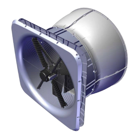
DA 800 LPC is an energy-efficient fan which includes a motor control. For LPC (Low Power Consumption)
and Dynamic MultiStep systems.
The fan is designed for mounting in DA 800 exhaust units in houses where ventilation is operated in low-
pressure ranges, i.e. in LPV and diffuse livestock houses.
1.1 Parts for DA 800 LPC
Figure
Description
445077 DA 800 LPC ventilator 0,75kW 230V 50/60Hz
Motorstyring
Motor 0,75 kW 1300 rpm
Ventilatorvinge
Ventilatorophæng og skruer
2 m skærmet motorkabel
445078 DA 800 LPC ventilator 1 kW 230V 50/60Hz
Motorstyring
Motor 1,2 kW 1300 rpm
Ventilatorvinge
Ventilatorophæng og skruer
2 m skærmet motorkabel
Accessories
Figure
Description
445076 LPC-2 relay module
Used if an alarm output or reversing of the fan is required.
1 x potential free output relay 1 A, 30 V DC/24 V AC.
1 x digital input.

Technical User Guide 7
DA 800 LPC
2 General Information
2.1 Recommended Tools
The following or similar tools are required to service the DA 800 LPC. The tools are not supplied by SKOV A/S.
Item
Description
Multimeter
Screwdriver set*
Allen key kit
Side cutting pliers
Long-nose pliers
Knife
Cordless drill
Screwdriver bits
Drill bits, various sizes
Ladder
Table 1: The most necessary tools for servicing the DA 800 LPC.
*Open the lid on the motor controller with:
Torx = T20
or
Allen key = H3
Straight slot screwdriver = SL 3,5
2.2 Warnings and Symbols
This manual uses the following symbols:
Warns of general dangers

8 Technical User Guide
DA 800 LPC
3 Mounting Guide
3.1 Positioning of Fan in the DA 600 Exhaust Unit
The wires to the fan must be short-circuited to avoid the fan rotating (driven by the air) as this
can lead to voltage in the wires.
The fan weighs around 13 and 16 kg.
Mount the four included fan suspension units in the exhaust unit
duct.
Position the legs of the fan in the four fan suspension units.
The fan is positioned in the fan suspension units of the exhaust
unit duct secured only by its own weight and it must therefore
be fastened in all four legs using split pins, strips or similar.
Important!
Check that the fan is correctly positioned in relation to the
direction of the air.
For air outlets, the fan blade must be at the bottom and the
motor at the top.
For air inlets, the motor must be at the bottom and the fan blade
at the top.
3.2 Safety Distance
If the distance from the floor to the fan blade is less than 270
cm, a safety net must be mounted in the bell mouth.
270 cm

Technical User Guide 9
DA 800 LPC
3.3 Mounting the Motor Control
Incorrect mechanical mounting can result in overheating and reduced performance.
3.3.1 Position of Motor Controller
Motor controller must not be built-in or covered and must
be mounted on a solid, level surface.
In order to uphold protection classifications, access and
cooling, the motor control must be positioned as shown in
3.3.1.
3.3.2 Ensure access and cooling of Motor Controller
In order to ensure access and cooling of the motor
controller, the distances to the surroundings of 150 mm
must be adhered to.

10 Technical User Guide
DA 800 LPC
3.3.3 Positioning of Motor Controller.
The motor controller is positioned so that the ambient
temperature is between - 40°C and + 50°C.
Mount the motor controller as close to the fan as possible.
The 2 m cable included must not be extended.
Mount the controller on a wooden plate fastened to a rafter on
the ceiling or directly on the chimney.
Install the controller under the eaves protected from driving rain
and in shade protected from direct solar radiation.

Technical User Guide 11
DA 800 LPC
4 Installation Guide
4.1 Electrical Connection
Qualified personnel must perform installation, service and fault-finding of all electrical
equipment in accordance with the applicable national and international standard EN 60204-1 and
any other EU standards that are applicable in Europe.
The installation of a power supply isolator is required for each motor and power supply to
facilitate voltage-free work on the electrical equipment. SKOV A/S does not supply the power
supply isolator.
4.1.1 Cabling in the Exhaust Unit
Drill a hole in the exhaust unit duct for the fan cable and pull it
along a leg to the same side as the motor controller.
4.1.2 Cabling into the Motor Controller
In order to prevent water from running into the motor
controller via cables and screwed connections, the cabling
must be carried out so that it can stand water around the
cable in the gasket of the screwed connection.

12 Technical User Guide
DA 800 LPC
4.2 Connection in the Motor Controller
4.2.1 Terminals for Power Supply
Power supply 1 x 230 V
4.2.2 Terminals for Power Supply of Fan
Remember to strip the cable so that the
protective shield from the fan can be connected
to the motor controller during mounting under
the rail.
Power supply 3 x 230 V from motor controller to
fan motor.

Technical User Guide 13
DA 800 LPC
4.2.3 Signal Terminals
4.2.4 Terminals on Relay Module (accessories)
Relay module 445076 can be purchased as accessories.
Ground
Normal = open
Reverse = GND (Jumper between terminal 15 and GND)
Not in use
Alarm NO
Max. 30 V DC/24 V AC, 1A
Alarm NC
Not in use
Not in use
Ground
Not in use
Signal from climate computer
Ground
10-0 V = open
0-10 V = GND (Jumper between terminal 7 and GND)
Stop = open
Start = GND (Jumper between terminal 8 and GND)
Not in use
Ground

14 Technical User Guide
DA 800 LPC
4.3 DA 800 LPC Fan
4.3.1 Wiring Diagram
shielded
Climate computer
DA 800 LPC
LPC fan

Technical User Guide 15
DA 800 LPC
4.3.2 Circuit Diagram
4.3.2.1 DA 800 LPC
Example of terminal number
For correct installation
see the setup menu
Show Installation on computer

16 Technical User Guide
DA 800 LPC
4.4 Dynamic MultiStep
4.4.1 Cable chart DA 800 LPC with DA 74CO ON/OFF
shielded
Climate computer
DA 74
DA 800 LPC
LPC fan

Technical User Guide 17
DA 800 LPC
4.4.2 Circuit Diagram ON/OFF
Power supply from emergency opening 0V-1 = Q1 terminal in Computer.
Power supply from emergency opening 24V-1 = Q2, Q3, Q4 and Q5 terminal in Computer.
Power supply from emergency opening 24V-12 = F6 terminal in emergency opening.
4.4.2.1 DA 800 LPC with DA 74CO ON/OFF
Example of terminal number
For correct installation
see the setup menu
Show Installation on computer
Power supply from
emergency opening
or internal 24 V
Q1
F6
Q2-Q5

18 Technical User Guide
DA 800 LPC
4.4.3 Cable Chart DA 800 LPC with DA 74CV Stepless
shielded
Climate computer
DA 74
DA 800 LPC
LPC fan

Technical User Guide 19
DA 800 LPC
4.4.4 Circuit diagram Stepless
Power supply from emergency opening 0V-1 = Q1 terminal in Computer.
Power supply from emergency opening 24V-1 = Q2, Q3, Q4 and Q5 terminal in Computer.
Power supply from emergency opening 24V-12 = F6 terminal in emergency opening.
4.4.4.1 DA 800 LPC with DA 74CV Stepless
Example of terminal number
For correct installation
see the setup menu
Show Installation on computer
Power supply from emergency
opening or internal 24 V
Q1
F6
Q2-Q5
When using ON/OFF 278M and 378M,
connect Q1 to B17 on main module.

20 Technical User Guide
DA 800 LPC
4.4.5 Cable Chart DA 800 LPC/DA 74CV with Reverse
shielded
Climate computer
DA 74
DA 800 LPC
LPC fan
Reverse
Key switch
This manual suits for next models
2
Table of contents
Other Skov Fan manuals

Skov
Skov DA 50-920 Manual

Skov
Skov DA 1200 Wall Inlet Installation instructions manual

Skov
Skov DOL 534 User manual

Skov
Skov DA 1700 Manual

Skov
Skov BF 50 Manual

Skov
Skov DA 600 LPC Manual

Skov
Skov BF 50 Manual

Skov
Skov BF 55 Manual

Skov
Skov DA 1700 LPC -3 Manual

Skov
Skov DA 600 Installation instructions manual
Popular Fan manuals by other brands

Global Industrial
Global Industrial 293129 user manual

Trendworx
Trendworx Charleston Instructions for use

NEFF
NEFF I97CQS9S5 User manual and installation instructiions

Midea
Midea FS40-16JR Service manual

Dräger Medical
Dräger Medical Oxylog 1000 Technical documentation

emerio
emerio FN-108784.1 instruction manual