Skov DOL 534 User manual

2018.04.23 • 604298
Software version 5.3
Natural Ventilation
DOL 534 • DOL 539 • DOL 634 • DOL 639
User and Technical Manual
English: For other language variants of this document we refer to:
Español: Para otras variantes del idioma de este documento, visite:
Français: Pour les versions dans d'autres langues de ce document veuillez consulter:
http://docs.skov.com/1174


Natural Ventilation
Program Version
The product described in this manual contains software. This manual corresponds to:
•Software version 5.3
It was released in 2018.
Product and Documentation Changes
SKOV A/S reserves the right to change this manual and the product described herein without further notice. In
case of doubt, please contact SKOV A/S.
Date of change appears from the front and the back page.
IMPORTANT
NOTES CONCERNING THE ALARM SYSTEM
Where climatic control is used in livestock buildings, breakdowns, malfunctions or faulty settings may cause
substantial damage and financial losses. It is therefore essential to install a separate, independent alarm system
which monitors the house concurrently with the climate and production controller. According to EU directives
98/58/EU an alarm system must be installed in any house that is mechanically ventilated.
Please note that the product liability clause of SKOV A/S’ general terms and conditions of sale and delivery
specifies that an alarm system must be installed.
In case of operating error or improper use, ventilation systems can result in production loss or
cause loss of lives among animals.
SKOV A/S recommend that ventilation systems should be mounted, operated and serviced only
by trained staff and that a separate emergency opening unit and an alarm system be installed as
well as maintained and tested at regular intervals, according to SKOV A/S’ terms and conditions
of sale and delivery.
Qualified personnel must perform installation, service and fault-finding of all electrical
equipment in accordance with the applicable national and international standard EN 60204-1 and
any other EU standards that are applicable in Europe.
The installation of a power supply isolator is required for each motor and power supply to
facilitate voltage-free work on the electrical equipment. SKOV A/S does not supply the power
supply isolator.
Note
•All rights reserved. No part of this manual may be reproduced in any manner whatsoever without the
expressed written permission of SKOV A/S in each case.
•SKOV A/S has made reasonable efforts to ensure the accuracy of the information contained in this
manual. Should any mistakes or imprecise information occur in spite of this, SKOV A/S would
appreciate being notified thereof.
•Irrespective of the above, SKOV A/S shall not have any liability with respect to loss or damage
caused or alleged to be caused by reliance on any information contained herein.
•Copyright 2018 by SKOV A/S.

4 User and Technical Manual
Natural Ventilation
USER MANUAL............................................................................................................5
1GUIDELINES ....................................................................................................5
2PRODUCT DESCRIPTION...............................................................................5
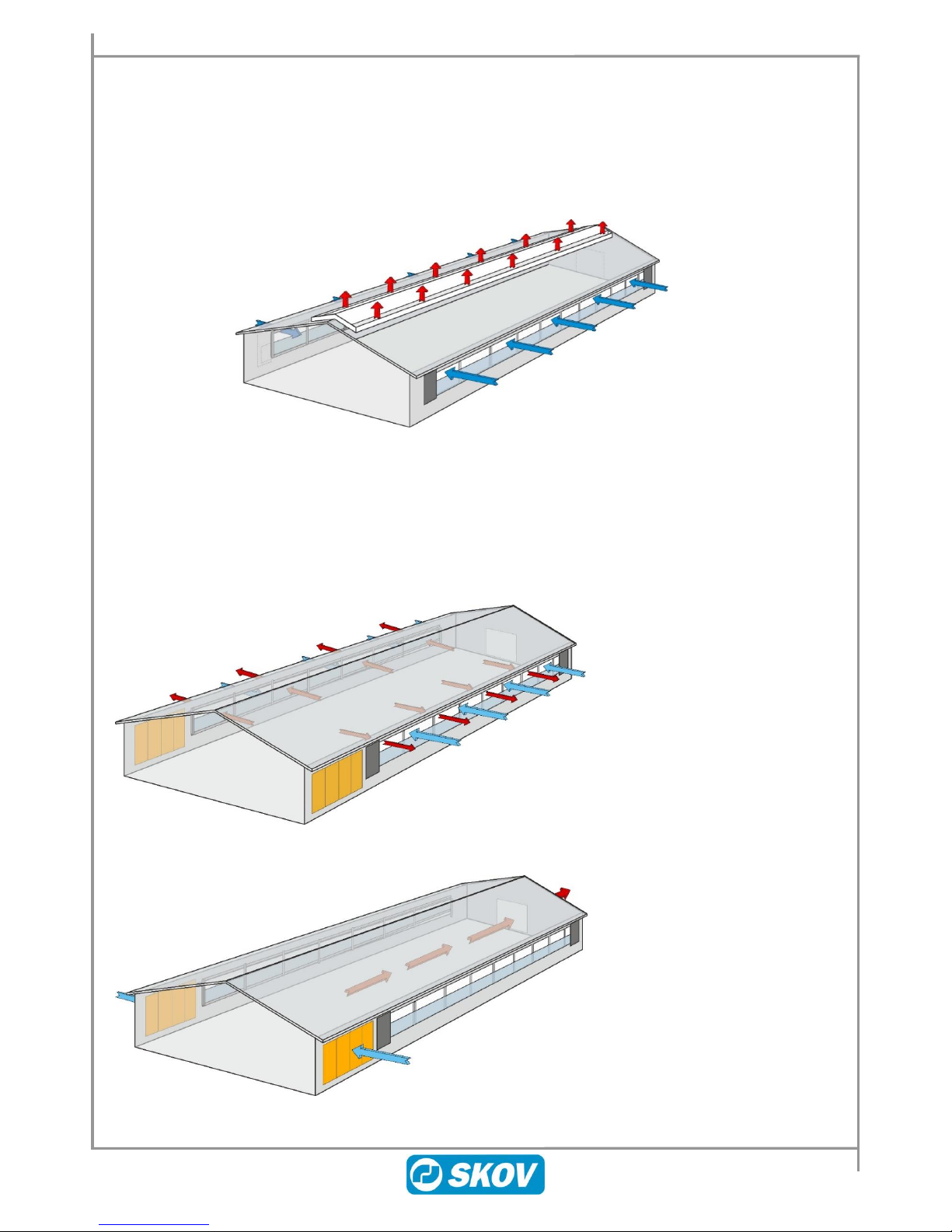
2.1 Pure Natural Ventilation...........................................................................................6
2.2 Natural Ventilation in Combination.........................................................................6
3USER GUIDE....................................................................................................7
3.1 Overview of User Menus..........................................................................................7
3.1.1 Natural ventilation combined with other ventilation principles ....................................... 9
3.1.1.1 Natural ventilation using CO2 sensor....................................................................................................10
3.1.2 Natural ventilation using weather station......................................................................... 11
3.2 Alarm Settings for Natural Ventilation..................................................................12
4MAINTENANCE GUIDE .................................................................................12
TECHNICAL MANUAL...............................................................................................13
5INSTALLATION GUIDE..................................................................................13
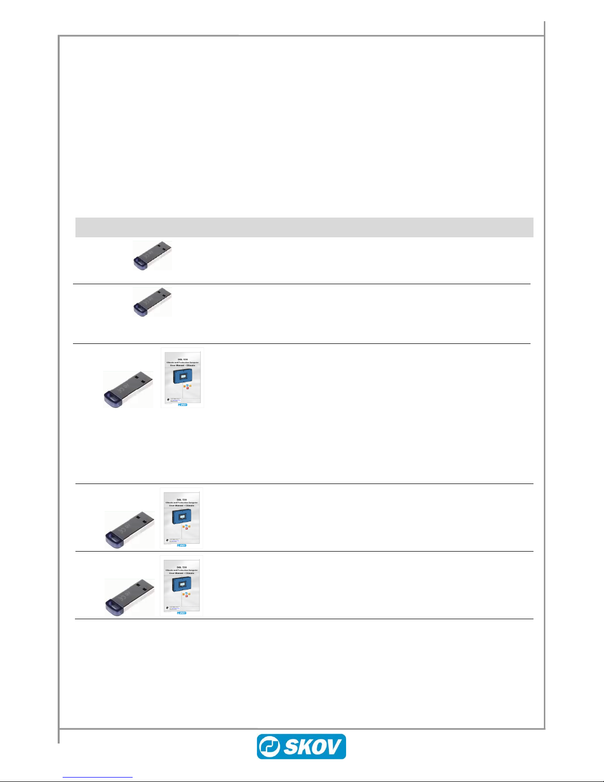
5.1 Working Procedure when Installing Feature Software........................................13
5.2 Backup of Settings .................................................................................................13
5.3 Loading Feature Software in Controller................................................................14
5.4 Installation...............................................................................................................15
5.5 Adjustment..............................................................................................................16
6CALIBRATION................................................................................................18
6.1 Calibration of Air Inlet and Air Outlet....................................................................18
6.2 Calibration of Weather Station ..............................................................................19
7TESTING.........................................................................................................19
8SETTINGS ......................................................................................................20
9CONTROL PARAMETERS ............................................................................21
10 ADJUST OPENING OF THE AIR INLETS AND AIR OUTLET......................22

User and Technical Manual 5
Natural Ventilation
USER MANUAL
1 Guidelines
This manual describes the specific functionality of Natural ventilation. For a general description of the
operation of the controller and other functions, see the user and technical manual supplied with the controller.
2 Product Description
Natural ventilation is supplied as part of the system software for the SKOV controllers or as a feature software
containing a specific functionality for post-installation in already working controllers.
Natural ventilation
136270 DOL 534 Natural, Poultry Climate SW
System software. Pure Natural ventilation without the possibility of
combination with other ventilation principles (LPV and Tunnel).
137284 DOL 634-1 Natural, Pigs Climate SW
137285 DOL 634-2 Natural, Pigs Climate SW
System software. Pure Natural ventilation without the possibility of
combination with other ventilation principles (LPV and Tunnel).
136280 Natural ventilation, Feature Software
Natural ventilation for post-installation in the climate controller already
working with LPV or Tunnel system software. When loading the
feature software, the new functions are added to the menus of the
controller.
Feature software can be installed in controllers, version 5.2 software or
later. If the controller software version is older than version 5.2, it
requires update to the latest version prior to installation of the software
feature.
Supplied with English user and technical manual.
136948 DOL 53X update, Poultry System SW
When updating DOL 53X software, the FarmOnline Explorer
management program requires update to the latest version.
136230 DOL 63X update, Pigs System SW
When updating DOL 63X software, the FarmOnline Explorer
management program requires update to latest version.

6 User and Technical Manual
Natural Ventilation
2.1 Pure Natural Ventilation
Using Natural ventilation, the air change happens when air currents move between the adjustable air inlet and
the air outlet without any assistance of fans. Curtain openings on the sides of the livestock house are typically
used as both air inlet and the air outlet. You can also use tunnel opening, open flap in exhaust unit or ridge
opening as air outlet. The mechanical regulation is solely opening and closing of the inlets and outlets. Since no
exhaustion takes place by means of fans, an energy saving is achieved and the noise level in the livestock house
is reduced.
Figure 1: Example of a naturally ventilated livestock house with curtain openings on the sides of the house and
ridge opening in the roof
2.2 Natural Ventilation in Combination
Natural ventilation can be combined with other ventilation principles (LPV, Tunnel and heat recovery)
depending on how the ventilation system is constructed. When the required climate can no longer be sustained
using natural ventilation, the ventilation system switches to a different ventilation principle, for instance based
on too high or low outside temperature, too high CO2level in the livestock house or too high wind velocities.
Figure 2: Example of naturally ventilated livestock house in combination with tunnel ventilation. Natural
ventilation
Figure 3: Example of naturally ventilated livestock house in combination with tunnel ventilation. Tunnel ventilation
Air outlet,
ridge opening
Air intake,
curtain opening
Air intake/air outlet,
curtain opening
Air outlet,
tunnel
opening
Air intake,
tunnel opening

User and Technical Manual 7
Natural Ventilation
3 User Guide
3.1 Overview of User Menus
Main Menu
Submenu
Climate
Ventilation
Minimum ventilation setpoints
Minimum ventilation natural
7%
Reduced minimum ventilation
Start at outside temperature
Max reduction at outside
temperature
Natural
Natural blocked information
Blocked by negative pressure
adjustment
Blocked by forced-to-stop input
Temp. setpoint incl. addition
19.0 °C
Combined with other ventilation principles
Natural, information blocked
Blocked by high outside temperature
Blocked by low outside temperature
Blocked by heat recovery unit
Stop Natural at outside temperature above
23.0 °C
Stop Natural at outside temperature below
21.0 °C
Start Natural at outside temperature above
16.0 °C
Start Natural at outside temperature below
14.0 °C
High outside temperature offset
4.0 °C
High outside temperature hysteresis
2.0 °C
Low outside temperature offset
-5.0 °C
Including weather station
Natural blocked information
Blocked by storm
Inlet maximum opening
Wind comfort at 15 m/s
4.0 °C
Wind comfort
0.0 °C
Storm limit
25.0 m/s
Maximum opening limit at high wind
speeds
30.0%
Maximum opening limit start wind speed
5.0 m/s
Maximum opening limit stop wind speed
10.0 m/s
Including CO2 sensor
Natural blocked information
Blocked by high CO2
Maximum CO2 level
3000 ppm
Info
Natural requirement zone X
39.1 %
Minimum ventilation reduced to
7.1 %
Minimum ventilation natural

8 User and Technical Manual
Natural Ventilation
Main Menu
Submenu
Climate
Humidity ventilation
0.0 %
Ventilation status
Natural inlet 1 position
Natural outlet 1 position
Weather station
Wind direction absolute
N
Wind direction relative
Rear
Air speed
0.0 m/s
Climate/ Ventilation/ Minimum ventilation setpoints
Minimum ventilation
natural
Setting in per cent of air inlet and air outlet opening. Lower limit for how little opening
you can have in Natural ventilation mode.
When Minimum ventilation natural is set to a value exceeding zero, the air inlet and air
outlet cannot close completely.
At batch production, the value follows a batch curve (Operation/ Batch curves/ Climate).
See the user manual supplied with the controller for a description of batch curves and
user offset.
Climate/ Ventilation/ Minimum ventilation setpoints / Reduced minimum ventilation
The function is intended for houses that require a better indoor temperature at the cost of accepting a slightly
poorer air quality. This may be necessary when it is extremely cold outside and the heating system cannot
provide sufficient heating.
Start at outside
temperature
Setting the outside temperature that will activate a reduction of the minimum
ventilation.
Max reduction at
outside temperature
Setting the outside temperature where the minimum ventilation is not further reduced.
See also section 9.
This function is an alternative to reducing the minimum ventilation via a CO2 sensor. However, this function
will take precedence if CO2 minimum ventilation is also used.
Climate / Ventilation /Natural
Temp. setpoint incl.
addition
Indication of corrected temperature value for Temperature setpoint + Wind comfort (or
Comfort).

User and Technical Manual 9
Natural Ventilation
3.1.1 Natural ventilation combined with other ventilation principles
Climate / Ventilation /Natural
Natural blocked
information
Indication of the reason why it is not possible to apply Natural ventilation.
Stop Natural at
outside temperature
above
Indication of the high outside temperature where natural ventilation stops (Temperature
setpoint+ High outside temperature offset).
Stop Natural at
outside temperature
below
Indication of the high outside temperature where Natural ventilation starts (Temperature
setpoint + High outside temperature offset - High outside temperature hysteresis).
Start Natural at
outside temperature
above
Indication of the low outside temperature where Natural ventilation starts (Temperature
setpoint + Low outside temperature offset + 2°C).
Start Natural at
outside temperature
below
Indication of the low outside temperature where Natural ventilation stops (Temperature
setpoint + Low outside temperature offset).
Example 1: Natural ventilation is active dependent on the current outside temperature
Outside temp. Temp. setpoint
High outside
temperature offset
Setting of a number of degrees added to the temperature setpoint to establish an upper
limit for the outside temperature. When outside temperature is above limit, ventilation
switches from Natural ventilation.
By changing this offset, you change the high temperature which starts and stops Natural
ventilation. Make the setting higher to switch to Natural ventilation at a higher
temperature.
High outside
temperature:hysteresis
Setting of a number of degrees which postpones the switch to Natural ventilation at
decreasing temperature. This makes regulation more stable so it does not constantly
switch between the various ventilation principles.
Low outside
temperature offset
Setting of a number of degrees subtracted from the temperature setpoint to establish a
lower limit for the outside temperature. When outside temperature is below limit,
ventilation switches from Natural ventilation. Make the setting higher to switch from
Natural ventilation at a lower temperature.
Tunnel min. vent. Natural Tunnel Natural Tunnel
min. vent.
Start Natural at outside temperature above
Stop Natural at outside temperature above
Start Natural at outside temperature below
Stop Natural at outside temperature below

10 User and Technical Manual
Natural Ventilation
Example 2: Natural ventilation is active dependent on the current outside temperature
Outside temp. Temp. setpoint
3.1.1.1 Natural ventilation using CO2 sensor
Using a CO2sensor, the current CO2 level in the livestock house can be monitored and used as an indicator of
the air quality.
Maximum CO2 level
Setting of upper CO2limit.
When the limit is exceeded, the controller switches to mechanical ventilation including
fans.
Natural Natural
Start Natural at outside temperature above
Hysteresis
Stop Natural at outside temperature above
Start Natural at outside temperature below
Hysteresis
Stop Natural at outside temperature below
High outside temp.
offset
Low
outside
temp.
offset

User and Technical Manual 11
Natural Ventilation
3.1.2 Natural ventilation using weather station
When Natural ventilation is combined with a weather station, it is possible to take the current wind direction
and wind speed into account by adjusting the ventilation.
Inlet maximum
opening
Indication of the maximum allowable opening of the individual air inlets.
The controller calculates the opening based on the current wind direction and speed. It
reduces the opening of the air inlets in the windward side and increases the opening in
the leeward side.
Wind comfort at 15
m/s
Setting of a number of degrees added to Temperature setpoint to minimise any draught
problems in case of strong wind.
Wind comfort
Indication of the number of degrees that have currently been added to Temperature
setpoint.
(Temperature setpoint +wind comfort at 15 m/s).
The controller calculates a gradually increasing wind comfort. This is calculated based
on the current wind speed (no addition at 0 m/s and maximum addition (4 °C) at 15
m/s). The addition is also corrected regarding wind direction (no addition in case of
wind direction along the livestock house to maximum addition if wind direction varies
from 60° to 90°).
Storm limit
Setting the upper wind speed limit.
The controller switches to ventilation using fans at the preset wind speed (only in
combination with other ventilation principles).
Maximum opening
limit at high wind
speed
Setting an opening limitation for the air inlet at high wind velocities (opening in per
cent).
Maximum opening
limit start wind speed
Setting the wind speed which is to activate a limited opening of the air inlet (wind
speed, 5 m/s). The air inlets can open 100% until the wind speed reaches this limit.
Maximum opening
limit stop wind speed
Setting the wind speed where the full opening limitation of the air inlet has been
reached (wind speed, 10 m/s). The air inlet can as a maximum open 30% when the wind
speed reaches this limit.
Example 3: Natural ventilation at increasing wind speeds
To counteract draught at increasing wind speed, the controller adds a number of degrees to the temperature
setpoint. It also gradually reduces the opening of the air inlets.
The opening of the air inlets is also determined by the current wind direction. The opening is thus reduced on
the side of the livestock house where the wind comes from. See also section 8.
See also section 6.2 for a description of weather station.
Opening limitation for the air inlet
Start Maximum
Wind velocity (m/s)
Storm limit
Switches from Natural
Wind comfort (Temp. setpoint addition)
Start Maximum

12 User and Technical Manual
Natural Ventilation
3.2 Alarm Settings for Natural Ventilation
Alarm settings
Climate
Inlet and outlet alarm
Error natural inlet
Disabled
Hard
Soft
Error natural outlet
Disabled
Hard
Soft
Error entrada natural
Inlet and outlet alarms are technical alarms.
The house controller triggers the alarm if the opening differs from the setting which
the controller calculates to be correct.
4 Maintenance Guide
There is no maintenance of software.
The functions from the feature software are not overwritten by a subsequent software update, but are updated
together with the latest update.
It is not possible to uninstall feature software once it is installed.

User and Technical Manual 13
Natural Ventilation
TECHNICAL MANUAL
This technical manual deals with the installation of the controller, and is aimed at the electricians who will be
installing and testing the controller.
The installation must be carried out by expert personnel and according to current national regulations - in
Europe also EU regulations.
Note that electrical equipment may not be opened without removing the supply voltage and that service and
troubleshooting may be carried out only by competent staff.
5 Installation Guide
Natural ventilation as feature software is supplied on a USB stick.
Important information
Feature software can only be installed in controllers, software version 5.2 or later version.
Loading a feature software usually takes up to two minutes.
The controller restarts after loading the feature software so it is not advisable to carry out
the upload when there are animals in the livestock house.
Should it be necessary to load the software while there are animals in the livestock house,
it should only be done in the presence of an animal expert.
5.1 Working Procedure when Installing Feature Software
1) Create a backup copy of the controller settings.
2) Load feature software.
3) Activate the Natural ventilation function.
4) Perform setup.
5) Make the settings.
5.2 Backup of Settings
1. Make a backup of the controller settings before installation of the feature software.
a. Select Save settings in the menu Technical/ Service/ Default setting/ Backup/ CPU module.
b. Rename the setup.
c. Wait until the controller indicates that the setup is saved.
d. Remove the USB stick and wait until the controller detects that the USB stick has been removed
(approx. 40 seconds).
If you do not wait long enough, the controller may have problems reading the next USB stick
correctly. This may lead to the following errors: The USB stick is not formatted correctly, resulting
in problems installing the software from the USB stick.

14 User and Technical Manual
Natural Ventilation
5.3 Loading Feature Software in Controller
2. Loosen the 4/6 screws (A) that hold the front panel in place.
3. Lift out the front panel.
Be careful not to pull the flat cable as this will damage the connector (B).
Unpack the USB stick and label from the cardboard box.
4. Place the small accompanying label next to the CPU module.
5. Insert the USB stick containing the feature software in the USB port (C) on the CPU module.
Select the required feature.
The installation process begins.
The controller restarts during installation.
It is VERY important not to interrupt the power supply while loading the system software.
Do not remove the USB stick until the loading process is fully completed. In other words, the
graphical user interface is accessible and usable.

User and Technical Manual 15
Natural Ventilation
5.4 Installation
Select Natural ventilation in the installation menu Technical/ Setup/ Installation/ Climate/ Natural ventilation.
The menu Installation
Climate
Sensors
Temperature sensors
1-8
Weather station
None
DOL 58 weather sensor
Weather station
CO2 sensor
Yes/No
One zone
Air inlet
Natural digital input
Yes/No
Natural inlet
Natural inlet 1-6
None
Relay with feedback
Relay without feedback
0-10V with feedback
0-10V without feedback
Air outlet
Natural outlet
Air outlet 1-3
None
Relay with feedback
Relay without feedback
0-10V with feedback
0-10V without feedback
Two zones
Air inlet
Natural digital input
Yes/No
Natural front/rear inlet
Front/rear inlet 1-2
None
Relay with feedback
Relay without feedback
0-10V with feedback
0-10V without feedback
Air outlet
Natural front/rear outlet
Air outlet front/rear
None
Relay with feedback
Relay without feedback
0-10V with feedback
0-10V without feedback
Natural ventilation can be used for both one and two zone housing.

16 User and Technical Manual
Natural Ventilation
5.5 Adjustment
The menu Adjustment
Climate
Natural temperature sensors setup
Natural outlet setup
At Natural ventilation, the opening of the air inlets is adjusted based on the input from the inside temperature
sensors - and possibly a weather station. The livestock house can be divided into areas. Each area can be
connected to one or several temperature sensors.
Setup of temperature sensors
You can set up several temperature sensors in the livestock
house to register the temperature in each zone.
If several sensors are being used for the same inlet, the same
inlet, the controller calculates an average temperature according
to which the controller carries out the regulation.
Setup of air outlet
The air outlets are controlled in relation to an average reading of
the opening of the selected air inlets.

User and Technical Manual 17
Natural Ventilation
Example 4: Setup of front display with Natural ventilation
It can be advantageous to set up the front display so that it reflects the installation in the house.
Air inlet
The temperature sensors have a central placement on the
display to indicate their placement in the house. Next to each
sensor, you find air inlet which is connected to the sensor in
question.

18 User and Technical Manual
Natural Ventilation
6 Calibration
Technical/ Calibration/ Climate
The menu Calibration
Calibrate inlets
Natural inlets
Autocalibration time of day
04:00 HH:MM
Per inlet
Running time
00:10 MM:SS
Runs before autocalibration
20
Minimum voltage
0.0 V
Maximum voltage
10.0 V
Inlet
35%
Calibration
Completed
ON
Calibrate outlet flap
Natural outlet flap
Autocalibration time of day
04:00 HH:MM
Outlet
35%
Calibration
Completed
ON
Minimum voltage
0.0 V
Maximum voltage
10.0 V
Calibrate climate sensors
Weather station
Rear end offset from north
0°
Wind direction minimum voltage
0.0 V
Wind direction maximum voltage
10.0 V
Wind speed minimum voltage
0.0 V
Wind speed maximum voltage
5.0 V
Wind speed minimum speed
0.0 m/s
Wind speed maximum speed
30.0 m/s
6.1 Calibration of Air Inlet and Air Outlet
See the technical manual supplied with the controller for a description of the calibration of the air inlet and air
outlet.

User and Technical Manual 19
Natural Ventilation
6.2 Calibration of Weather Station
The weather station is used in connection with natural ventilation, where it is indispensable to know the wind
direction and speed to be able to regulate the air inlets (openings) with due consideration of the weather
situation.
See also section 8.
Display reading
Functional explanation
Rear end offset from north
Set the number of degrees that the geographical location of the
livestock house deviates from northerly direction.
Wind direction minimum voltage
Wind direction maximum voltage
Wind speed minimum voltage
Wind speed maximum voltage
Adjust the voltage via Minimum voltage and Maximum voltage.
Wind speed minimum speed
Wind speed maximum speed
Enter a Minimum value as well as a Maximum value to indicate
the area within which the weather station can measure.
Figure 4: Offset of the location of the house - north being the point of orientation
7 Testing
Technical/Manual/Auto
The menu Manual/Auto
Manual/Auto
Manual
ON/OFF
Climate
Natural
Natural forced-to-start input
Natural forced-to-stop input
Natural inlet
Inlet 1 required
Inlet 1 position
Natural outlet
Outlet 1 required
Outlet 1 position
Air inlet and the air outlet shall be tested as described in the technical manual supplied with the controller.

20 User and Technical Manual
Natural Ventilation
8 Settings
Technical/ Service/ Default settings/ Climate/ Natural
This section is only relevant to houses with weather station.
The menu Natural
Natural
Location
Air inlet
Side/Location
Limitation factor
2.0
Cancellation of limitation at outside
temperature above setpoint
4 °C
Display reading
Functional explanation
Location
Side
Location
Indicate where the air inlets are placed physically in the house.
This is used when the inlets are also regulated in relation to the wind direction.
Side: Right or left side of the house.
-Location: Front, centre or rear of the livestock house
(in relation to the airflow direction (only at 1 zone).
Limitation factor 2.0
The controller limits the opening of the air inlets using the set factor.
Cancellation of limitation at outside
temperature above setpoint
4 °C
When the outside temperature is the set number of degrees exceeding
Temperature setpoint, the controller reduces limitation of the opening of air
inlets.
Example 5: Natural ventilation using weather station
Left
Right
Front
Middle
Rear
Other manuals for DOL 534
4
This manual suits for next models
3
Table of contents
Other Skov Fan manuals

Skov
Skov DA 1200 Installation instructions manual

Skov
Skov DA 600 LPC Manual

Skov
Skov DA 1700 Manual

Skov
Skov DA 600 Manual

Skov
Skov BF 50 Manual

Skov
Skov DA 1700 Manual

Skov
Skov BF 50 LPC-3 Manual

Skov
Skov DA 1200 Wall Inlet Installation instructions manual

Skov
Skov DA 60-920 Manual

Skov
Skov ECT 632-6 Manual
Popular Fan manuals by other brands

AERMEC
AERMEC FCS-ACT Direction for use and installation

Videsur
Videsur VSBFN55 user manual

Trebs
Trebs Comfort Air 99381 manual

Casablanca
Casablanca Holliston 59532 Owner's guide and installation manual

Progress Lighting
Progress Lighting AirPro P250107 installation manual

Jata
Jata JVVT3043 Instructions of use