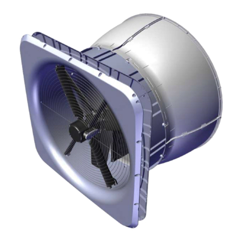
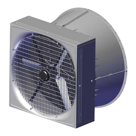
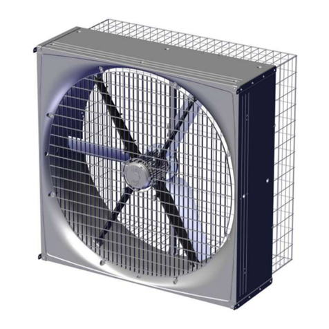
Skov BF 50 Manual

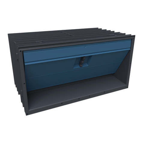
BF 50 Shutter
Technical User Guide
604441 • 2021-06-14
English For other language variants of this document we refer to:
Español Para otras variantes del idioma de este documento, visite:
Français Pour les versions dans d'autres langues de ce document veuillez consulter:
http://docs.skov.com/1241

BF 50 Shutter
2 Technical User Guide
Product and Documentation Changes
SKOV A/S reserves the right to change this document and the product herein described without further notice.
In case of doubt, please contact SKOV A/S.
The date of change appears from the front and back pages.
Note
• All rights belong to SKOV A/S. No part of this manual may be reproduced in any manner whatsoever without
the expressed written permission of SKOV A/S in each case.
• All reasonable efforts have been made to ensure the accuracy of the information contained in this manual.
Should any mistakes or imprecise information occur in spite of this, SKOV A/S would appreciate being noti-
fied thereof.
• Irrespective of the above, SKOV A/S shall not accept any liability with regard to loss or damage caused or
alleged to be caused by reliance on any information contained herein.
• Copyright by SKOV A/S.

BF 50 Shutter
1 Product description........................................................................................................................................5
2 Product survey ...............................................................................................................................................6
2.1 BF 50 shutter ............................................................................................................................. 6
2.2 Accessories................................................................................................................................ 7
3 Mounting guide...............................................................................................................................................8
3.1 Recommended tools.................................................................................................................. 8
3.2 Placement of BF 50 ................................................................................................................. 10
3.3 Preparing hole in wall.............................................................................................................. 10
3.3.1 Necessary space for BF 50 ....................................................................................................... 10
3.3.2 Measurements for square hole in wall ....................................................................................... 11
3.3.3 Measurements for square hole in wall with cone ....................................................................... 12
3.4 Measure and saw out the holes.............................................................................................. 13
3.5 Drainage holes ......................................................................................................................... 14
3.6 Mounting in wall....................................................................................................................... 15
3.6.1 Mounting with four brackets ....................................................................................................... 16
3.6.2 Mounting of four angle bars ....................................................................................................... 17
3.6.3 Mounting in wooden frame......................................................................................................... 18
3.6.4 Foaming ..................................................................................................................................... 19
3.6.5 Pointing ...................................................................................................................................... 22
3.7 Mounting of inside safety net ................................................................................................. 23
3.8 Manual opening of motor controlled shutter ........................................................................23
3.9 Mounting the cone ................................................................................................................... 26
3.10 Mounting of accessories......................................................................................................... 27
3.10.1 Outside safety net ...................................................................................................................... 27
3.10.2 Light trap .................................................................................................................................... 27
4 Installation guide ..........................................................................................................................................29
4.1 Electrical connection............................................................................................................... 29
4.2 Cabling to connection box...................................................................................................... 29
4.3 Connection to actuator............................................................................................................ 29
4.4 Connection of extra 24 V power supply................................................................................. 30
4.5 General information about circuit diagrams ......................................................................... 31
4.5.1 Color code.................................................................................................................................. 31
4.5.2 Power supply isolator................................................................................................................. 31
4.5.3 Letter Code ................................................................................................................................ 31
4.6 Cable plans and circuit diagrams........................................................................................... 32
4.6.1 BF 50 shutter VAR cable plan ................................................................................................... 32
4.6.2 BF 50 shutter VAR circuit diagram ............................................................................................ 32
4.6.3 BF 50 shutter ON/OFF cable plan ............................................................................................ 33
4.6.4 BF 50 shutter ON/OFF circuit diagram ..................................................................................... 33
5 Maintenance instructions ............................................................................................................................34
5.1 Recycling/Disposal .................................................................................................................. 34
6 Troubleshooting ...........................................................................................................................................35
7 Technical data...............................................................................................................................................36
7.1 BF 50 shutter air output ......................................................................................................... 36
7.2 BF 50 shutter ........................................................................................................................... 36
7.3 Metal and plastic parts ............................................................................................................ 37
7.4 Light traps ................................................................................................................................ 38
7.5 Dimensioned sketch ................................................................................................................ 39
Technical User Guide

BF 50 Shutter
Technical User Guide
7.5.1 BF 50 shutter ............................................................................................................................ 39
7.5.2 Light trap .................................................................................................................................... 39

BF 50 Shutter
Technical User Guide 5
1 Product description
BF 50 shutter is used in SKOV A/S positive pressure systems where the incoming air is filtrated to avoid air-
borne diseases from infecting the animals.
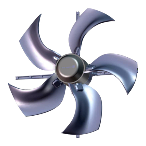
BF 50 shutter is without fan but with cone and shutter controlled by a stepless or ON/OFF actuator. The shutter
is controlled in relation to the amount of air passing through the livestock house while maintaining the positive
pressure in the house to prevent unfiltered air from entering though leaks.
BF 50 cone helps to prevent air entering from the outside through the shutter.
BF 50 shutter is a corrosion-free shutter.
BF 50 shutter is supplied without outside safety net - this can be ordered as an accessory.
BF 50 is specially designed for harsh livestock house environments. This applies to both climatic and electrical
influences.
Central positive pressure system with filters and exhaust via BF 50 shutter.
Fans
Pads
Filters
BF 50 shutter

BF 50 Shutter
6 Technical User Guide
2 Product survey
2.1 BF 50 shutter
435393 BF 50 shutter VAR with actuator and cone
BF 50 shutter VAR is used for positive pressure systems.
BF 50 shutter VAR is without fan but with cone and shutter controlled by a
stepless actuator. The stepless shutter is controlled in relation to the
amount of air passing through the house while maintaining the positive
pressure in the house to prevent unfiltered air from entering though leaks.
24 V DC stepless actuator with 2.5 m cable.
Is supplied assembled without outside safety net. However, the cone must
be assembled and mounted on site.
435341 BF 50 shutter ON/OFF with actuator and cone
BF 50 shutter ON/OFF is used for positive pressure systems.
BF 50 shutter ON/ OFF is without fan but with cone and shutter controlled
by an ON/ OFF actuator. The ON/OFF shutter is controlled in relation to the
amount of air passing through the house while maintaining the positive
pressure in the house to prevent unfiltered air from entering though leaks.
24 V DC ON/OFF actuator with 2.5 m cable.
Is supplied assembled without outside safety net. However, the cone must
be assembled and mounted on site.

BF 50 Shutter
Technical User Guide 7
2.2 Accessories
435396 BF 50 safety net outside for cone, A2
The outside safety net for cone is used where extra safety is required.
Supplied with mounting parts.
1 per wall fan.
435156 50" light trap brown out
Used if dimming is required in the livestock house.
Light reduction factor 175.000:1.
The light trap reduces the air output of the fan without cone by approx. 15
% at 0-70 Pa pressure difference.
The light trap reduces the air output of the fan with cone by approx. 18 % at
0-70 Pa pressure difference.
Supplied as an unassembled unit incl. brackets.
1 per wall fan.
435158 50" light trap black out
Used if a large amount of dimming is required in the livestock house.
Light reduction factor 1.300.000:1.
The light trap reduces the air output of the fan without cone by approx. 31
% at 0-70 Pa pressure difference.
The light trap reduces the air output of the fan with cone by approx. 35 % at
0-70 Pa pressure difference.
Supplied as an unassembled unit incl. brackets.
1 per wall fan

BF 50 Shutter
8 Technical User Guide
3 Mounting guide
Check that the parts ordered are present and undamaged before starting work. Please read through the entire
guide before starting assembly and fitting.
If the BF 50 is installed in areas with risk of ice/snow slide, precautions must be made to
avoid damage to the BF 50.
3.1 Recommended tools
A list of the recommended tools for mounting purposes can be seen below.
Item Description
Cordless drill
Screwdriver bits
Drill kit
Atomizer
Sealant gun
Hammer
Utility knife
Wedge
Marker pen
Torque wrench
Tape measure
Combination spanner kit
Screwdriver

BF 50 Shutter
Technical User Guide 9
Item Description
Foam gun
Ladder
Jigsaw
Socket wrench set
Spirit level
Try square

BF 50 Shutter
10 Technical User Guide
3.2 Placement of BF 50
BF 50 must be placed in the livestock house according to the drawing supplied. Contact SKOV A/S if major
changes are made.
Check that all BF 50 can be placed freely in relation to other housing equipment upon agreement with the client.
Place the insulation of the brickwork all the way in against the BF 50 and all the way round (as in other building
constructions). This way you prevent a cold bridge along the side of BF 50 from being formed.
3.3 Preparing hole in wall
3.3.1 Necessary space for BF 50
(B)
(C)
(D)
(E)
(A)
There must be a minimum of (A) space inside the live-
stock house for the BF 50.
There must be minimum of (B) of space including the
wall thickness outside the livestock house for the BF
50.
Wall thickness (C).
The recommended space in front of the cone is (D).
Recommended installation height from floor is mini-
mum (E) in order to ensure space for dung removal.

BF 50 Shutter
Technical User Guide 11
3.3.2 Measurements for square hole in wall
The dimensions below are given in mm.
Recommended measurements for individual mounting of the BF 50.
Minimum distance from BF 50 to wall, floor and ceiling

BF 50 Shutter
12 Technical User Guide
3.3.3 Measurements for square hole in wall with cone
The dimensions below are given in mm.
Recommended measurements for individual mounting of BF 50 with mounted cone.
Minimum distance from BF 50 to wall, floor and ceiling

BF 50 Shutter
Technical User Guide 13
3.4 Measure and saw out the holes
Remember to always use a spirit level.
Drill 10 mm holes all the way through the wall.
Cut the holes.

BF 50 Shutter
14 Technical User Guide
3.5 Drainage holes
Yellow
Black
Please note that the yellow blanking plug must be at
the top.
If parts of BF 50 are outside the wall, on the outside, it
is recommended to drill 4 pcs. 5 mm drain holes in the
bottom on the four markings.

BF 50 Shutter
Technical User Guide 15
3.6 Mounting in wall
190 mm
(A)
Lead the cables into the livestock house.
Make sure that there is free space for cables.
Measure from the top of BF 50 down (A) make a hole
in the wall for the cables as the bending radius of the
fan cables is 50 mm.
Use wedges to center BF 50 in the hole.
BF 50 must be level.

BF 50 Shutter
16 Technical User Guide
3.6.1 Mounting with four brackets
Mount 2 brackets (not supplied) in the bottom of BF 50
to fit the wall thickness.
Place BF 50 in the wall.
Use wedges to center BF 50 in the hole.
Tip BF 50 so that the 2 internal brackets can be
mounted. The brackets must be in line with wall.

BF 50 Shutter
Technical User Guide 17
3.6.2 Mounting of four angle bars
Mount the 4 angle bars (not supplied) on BF 50 to fit
the wall thickness.
Place BF 50 in the wall.

BF 50 Shutter
18 Technical User Guide
3.6.3 Mounting in wooden frame
Mount the wooden frame with brackets (not supplied).
Place BF 50 in the wall.

BF 50 Shutter
Technical User Guide 19
Remove the net, see section Mounting of inside safety
net(Mounting of inside safety net).
Pre-drill 8 holes for mounting on wall.
Screw BF 50 into the wall with 8 screws, with a length
of minimum 150 mm.
3.6.4 Foaming
SKOV A/S recommends using single-component polyurethane foam or similar.
Check before foaming how much the foam expands.
An external angle bracket can be used to for completion
(not supplied by SKOV A/S).

BF 50 Shutter
20 Technical User Guide
Wet the faces with water from a mist sprayer before pro-
ceeding with the foaming.
Foam around BF 50 as shown in the drawing. Foam the
wall fan’s corners and approx. 100 mm to each side
foam the entire depth of the BF 50.
Other manuals for BF 50
2
Table of contents
Other Skov Fan manuals

Skov
Skov DA 1200 Wall Inlet Installation instructions manual

Skov
Skov DA 50-650 Manual

Skov
Skov ECT 632-6 Manual

Skov
Skov DA 60-920 Manual

Skov
Skov DA 600 LPC Manual

Skov
Skov DA 1700 LPC -3 Manual

Skov
Skov DA 60-920 Manual

Skov
Skov BF 50 LPC-3 Manual

Skov
Skov DOL 534 User manual

Skov
Skov DA 820 LPC -3 Manual