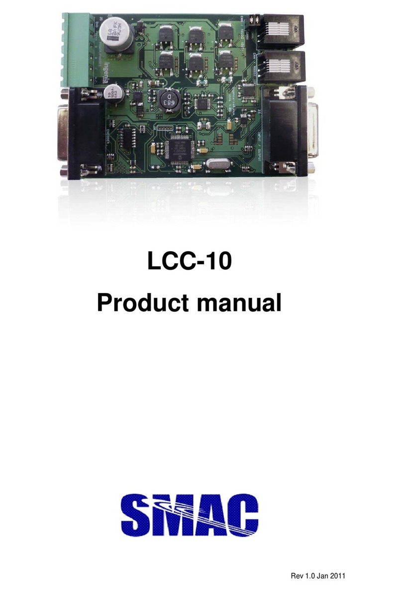
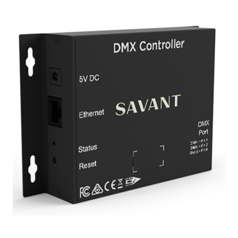
SMAC LAC-15 User manual

LAC-15
Single Axis Controller/Amplifier
User Manual
Version A

LAC-15, 1Axis Controller/Amplifier User Manual Ver.A 2
Contents
LAC-15 Specification and Features ............................................................................................................ 3
Outline Drawing .......................................................................................................................................... 4
LAC-15 Pin Layout ..................................................................................................................................... 5
Digital I/O Interface ..................................................................................................................................... 6
Analog Inputs .............................................................................................................................................. 7
DC Brush and Brushless Motor connection................................................................................................ 8
Differential Encoder Connection.................................................................................................................. 9
Power Supply Connection......................................................................................................................... 10
Serial RS232 Interface connection.............................................................................................................. 11
CAN Connection ....................................................................................................................................... 12
Available Memory Area ............................................................................................................................ 13
Programming .............................................................................................................................................. 14
What You will Need ................................................................................................................. 14
Installing the EasyM otion Studio Software .............................................................................. 14
Project Set-up ........................................................................................................................... 16
Motor Setup.............................................................................................................................. 18
Encoder data entry ................................................................................................................... 19
Drive Setup ............................................................................................................................... 20
Program Motion ........................................................................................................................ 31
EasyM otion Studio includes a Motion Wizard. ....................................................................... 33
Sample M otion Program .......................................................................................................... 35

LAC-15, 1Axis Controller/Amplifier User Manual Ver.A 3
LAC-15 Specification and Features:
Number of M otion Axis 1
Control Algorithm PID
Speed of DSP Controller 40 M Hz, 40 M IPS
Motor Control DC Brush, DC Brushless
Operation M ode Stand along, Slave – in multi-axis
Control M ode Position, Velocity, Torque, Open Loop
Nominal PWM Frequency 20 KHz
Main Power Supply 12 – 48 VDC
Peak Current 6 A
Continuous Current 3 A
Logic Supply 5 VDC, 600 mA
Encoder Supply 5 VDC
Encoder and Index Input Single Ended or Differential
Encoder Count Rate 6.7 M Hz M ax.
Position Range 32 bits
Velocity Range 16 bits integer part, 16 bits fractional part
Acceleration Range 16 bits integer part, 16 bit fractional part
Feedback Signal Incremental encoder, Index, Hall, Current, speed
estimated from position, DC bus voltage
General Digital Input 4, TTL
General Digital Output 4, TTL
Dedicated Digital Input 6, TTL
Dedicated Digital Output 2, TTL
Analog Input 2, with 10 bit resolution and ±10V
Programming platform EasyM otion Studio
Internal M emory 1.5K x 16 SRAM
External Memory 8K x 16 serial E²ROM
Communication Interface
1 Port
RS232 up to 115200 bps
CAN bus 2.0B up to 1M bit/s
Integrated Protections Over Voltage, Over Current, Under Voltage, Over
Temperature, I²t
Operation Ambient
Temperature
0 – 40 °C
Dimension 198 mm x 96 mm x 61 mm

LAC-15, 1Axis Controller/Amplifier User Manual Ver.A 4
utline Drawing:
SMAC LAC-15, the new 1-axis motion controller-drive is engineered with a
Technosoft ISM4803 high-performance intelligent servo module, which is combining
motion controller and drive functionalities into a single compact unit. The LAC-15
ISM module is a flexible, cost effective and compact solution, particularly adapted for
distributed and coordinated control of brushless, DC, linear or step motors of powers
up to 150W, with voltages up to 48V. Typical applications include distributed motor
control with possibilities of gearing and electronic CAM functions in a CAN network
operation. Targeted for medium to high volume applications, the ISM hardware
structure is based on a cost optimized design integrating all the basic motor control
functions on one double-sided card format. A series of I/O signals, both digital and
analogue, are available for easy interfacing with the application. A complete set of
high-level Technosoft Motion Language (TML) instructions permit to define and start
complex motion sequences from your host, PC, or to execute pre-stored motion
sequences selected from I/O lines, in a stand-alone mode.
The embedded Intelligence of the ISM facilitates the configuration and programming
of the module through a high level graphical interface as the EasyMotion Studio.

LAC-15, 1Axis Controller/Amplifier User Manual Ver.A 5
LAC-15 Pin Layout
J1 – User I/O Interface Connector
High Density DB-26, Fema e
1. Aixs-1, OUT_0
2. NC
3. Axis-1, IN_1
4. NC
5. Axis-1, OUT_3
6. NC
7. Axis-1, FDBK
8. NC
9. NC
10. Axis-1, ENABLE
11. Axis-1, IN_0
12. NC
13. Axis-1, OUT_2
14. NC
15. Axis-1, IN-3
16. NC
17. NC
18. NC
19. 5 VDC
20. GND
21. Axis-1, OUT_1
22. NC
23. Axis-1, IN_2
24. NC
25. Axis-1, REF
26. NC
J2 – RS232 & CAN Communication
Interface
6 pin Phone Modu e
1. CAN-L
2. CAN-H
3. Rx, Receive Data
4. Tx, Transmit Date
5. GND
6. NC
J4 – Serv o Encoder Interface Connector
High Density DB-26, Fema e
1. NC
2. NC
3. NC
4. 5 VDC
5. 5 VDC
6. NC
7. NC
8. Axis-1, Encoder B-
9. Axis-1, Encoder B
10. NC
11. NC
12. NC
13. GND
14. GND
15. NC
16. NC
17. Axis-1, Encoder A-
18. Axis-1, Encoder A
19. NC
20. NC
21. GND
22. GND.
23. NC
24. NC
25. Axis-1, Encoder Index-
26. Axis-1, Encoder Index
J5 – Pow er Interface
5 Pin 5.08mm Center Phoenix
1. Axis-1, W
2. Axis-1, Motor- / V
3. Axis-1, Motor / U
4. Main Power, 24V
5. Main Power, Return
Pin 1
Pin 1
J1
Pin 1
Axis
-
1
Pin 1
J4
J5
J2

LAC-15, 1Axis Controller/Amplifier User Manual Ver.A 6
Digital I/ Interface
The LAC-15 provides total 4 general purpose inputs and 4 general purpose output. In addition, each
axis has 3 dedicated inputs, Enable, Limit+ and Limit-, and 2 dedicated outputs, Ready, and Error.
All inputs and outputs are compatible with TTL signal level and maximum current on outputs is 24
mA each.

LAC-15, 1Axis Controller/Amplifier User Manual Ver.A 7
Analog Inputs
The LAC-15 provides total 2 analog inputs with 10 bits resolution on A/D conversion; two analog
inputs are REF and FDBK. The analog input range is +/- 10V that reference to GND. The input REF
can be used as analog position, speed reference, and torque reference. The input FDBK can be used
as tacho meter feedback.

LAC-15, 1Axis Controller/Amplifier User Manual Ver.A 8
DC Brush and Brushless Motor connection
CAUTI ':
Before connecting the motor, be sure you have the
right application programmed to E²R M otherwise you
can damage the motor and drive.
At Power-on the TML application is automatically
executed. See special instruction on how to disable this
auto run feature.

LAC-15, 1Axis Controller/Amplifier User Manual Ver.A 9
Differential Encoder Connection
The LAC-15 provides 2 channels (A and B) of quadrature encoder interface with index signal input.
+5VDC requires minimum of 50mA.

LAC-15, 1Axis Controller/Amplifier User Manual Ver.A 10
Power Supply Connection
The LAC-15 has wide range of Motor Power (Vmot) input between 12 to 48 V DC. The maximum
supply Voltage is 50VDC.

LAC-15, 1Axis Controller/Amplifier User Manual Ver.A 11
Serial RS232 Interface connection
The LAC-15 provides a serial RS232 communication interface, one independent RS232 port.
LAC-15 communicates with a host computer via RS232 port. The RS232 port has compliance with
standard of TIA/EIA-232-C. The baud rate can be set between 9600 to 115,200 bits per second.

LAC-15, 1Axis Controller/Amplifier User Manual Ver.A 12
CA' Connection
The LAC-15 provides one port of CAN communication interface.. LAC-15 CAN ports have
compliance with standards CAN-Bus 2.0B; ISO11898-2. The speed of CAN bus can be up to 1M
bits per second. Two and more LAC-15 can be linked in chain to form CAN network. Terminator
resistor of 120 ohm is needed to install into the network at last node axis. In the multiple-axis CAN
network, the aixsID must be set to each axis node. The first axis (axis-1) node should set the axisID
as 255. The second axis (axis-2) can be assigned axisID between 1 – 254. The axisID can be set by
software and/or by hardware (by jumpers)

LAC-15, 1Axis Controller/Amplifier User Manual Ver.A 13
Available Memory Area
The LAC-15, the single axis controller driver, has two types of memory a 1.5Kx16 SRAM (internal)
memory and an 8Kx16 serial E²ROM (external) memory.
The SRAM memory is mapped both in the program space (from 8200H to 87FFH) and in the data
space (from A00H to FFFH). The data memory can be used for real-time data acquisition and to
temporarily saved variables during a TM L program execution. The program space can be used to
download and execute TM L programs. It is the user’s choice to decide how to split the 1.5-K SRAM
into data and program memory.
The E²ROM can be imaged as 8Kx16 program memory mapped in the address range 4000H to
5FBEH. It offers the possibility to keep TM L programs in a Non-volatile memory. Read and write
accesses to the E²ROM locations, as well as TML programs downloading and execution, are done
from the user’s point of view similarly to those in the SRAM program memory. The E²ROM SPI
serial access is completely transparent to the user.

LAC-15, 1Axis Controller/Amplifier User Manual Ver.A 14
Programming
Easy Motion Studio
Easy M otion Studio provides high level graphical development environment. It supports the
configuration, parameterization and programming of the drive through
● Motion system set-up wizard
● Tuning assistance
● Definition, programming and testing of motion sequences.
What You will 'eed:
● Host computer An IBM PC, AT or compatible, with hard disk, CD-ROMM drive, NGA or
SVGA monitor, running under Windows (version 95, or 98, Millennium, or NT4.0, or 2000, or
XP). Windows M E is not supported
● Power requirements 12 – 48 VDC with up to 3A(rms) load current for motor.
● Controller LAC-15 with appropriable cable
● Motor SM AC linear actuator or linear/rotary actuator.
● Port Asynchronous RS-232 serial communication link
● Serial cable SM AC communication kit
Installing the EasyMotion S tudio S oftware
● Insert the setup CD-ROM into the CD-ROM drive unit and setup program will automatic
starting. If the automatic starting failed, go CD-ROM drive folder and start S etup.exe file.
● Select the “EasyM otion Studio” menu item
● After entering “EasyM otion Studio Software”
page, press the “EasyMotion Studio Setup”.
● Following the instructions and answer the
questions during the installation procedure.

LAC-15, 1Axis Controller/Amplifier User Manual Ver.A 15
Verifying the Installation:
● Connecting the communication cable to PC and LAC-15
● Powering up the drive
● Starting EasyM otion Studio by using the Windows “S tart | Programs | EasyMotion Studio |
EasyMotion Studio” menu command
● If the communication works properly you will see displayed on the status bar (the bottom line) of
the EasM otion Studio, “Online”, the axis ID of the drive, and the firmware version.
● If the LAC-15 is not detected, the “offline” message is displayed on the status bar. First, checking
the serial cable and, power supply connections to the LAC-15. Also checking the serial port set, it
may be used by other devices. After the problems being fixed, use menu command
“Communication | Refresh” to restore the connection.

LAC-15, 1Axis Controller/Amplifier User Manual Ver.A 16
n-line Help
Now, the communication connection between LAC-15 controller and your PC has been established.
For the first time using EasyMotion Studio, it is recommended that you first read the “Getting
S tarted” that included in the on-line help. With menu command “Help | Getting S tarted”, you will
see the different tutorial lessons that are also available.
Project S et-up:
After launching EasyMotion Studio, an empty window is created in where you can create a new
project or open a previous created project.
Press New button to open a “New Project” dialogue. Set the axis number for your
application equal to the drive axis ID. The initial default number is 255, the default axis ID of the
drive. Press 'ew button and select the drive type of IS M4803-CA', the motor technology of
BRUSH M T R and feedback device of Incremental Encoder.

LAC-15, 1Axis Controller/Amplifier User Manual Ver.A 17
EasyM otion Studio opens a Project window as following left side shows the project structure and
right side is application information. At beginning both the new project and its first application are
named “Untitled”. The application has two components S Setup and M M otion (program)
In the left side of project window, select “S Setup” to bring up the Setup application.

LAC-15, 1Axis Controller/Amplifier User Manual Ver.A 18
Press View/Modify button, . It opens two setup
windows, Motor S etup and Drive S etup. Through these two dialogue setup, you can configure the
motor data and set the parameter values in the drive for your application. A series tests help to check
the connections to the drive and/or to determine the motor and sensors parameters. In each setup
dialogue, a guideline assistant will guide you through the whole process of checking data.
Motor S etup
In the M otor Setup windows, motor specification data entry here. The key data is the set of motor
wire resistance, inductance, and torque consistence. The motor Normal current and Peak current are
also two critical data.
Check carefully the motor 'ormal current and Peak current values. During the motor tests,
the power is applied to motor and test current is based on the motor nominal current and the
set of over current protection function of peak current. If those two values are incorrectly
entry, the test can damage motor!
There are two methods to configure the motor, choose one from existing data base; or modify one
motor to create new one.

LAC-15 2Axis Controller/Amplifier User Manual Ver.C
19
In the first case, choosing one from Database, User, then go through Motor list. Select one motor,
for example LAL35-025-75. The LAL35 actuator has 25mm stroke, 48V single coil and 5um encoder.
If the actuator that to be run is slight different, for example it has hot coil, you need to adjust the data
accordingly. In the second case, start from an actuator in the database and modify the data to be the
new actuator. When you make some changes in the existent actuator, the actuator name gets the
suffix (Modified). It indicates that you can save the actuator data in the database User with the
proper name. Press the Save to User Database button for the operation.
In the User database, you may also Delete motors/actuators when you don’t need it.
Encoder data entry:
Since the same type of actuators may have different resolution of encoder, the data entry here needs
to be adjusted accordingly. Select Incremental encoder on motor radio button first.
The number of line per revolution is determined according to encoder resolution, number encoder
count per mm divided by 4.
Encoder resolution (um) Encoder count / mm Lines / mm
5 200 50
1 1,000 250
0.5 2,000 500
0.1 10,000 2,500
0.05 20,000 5,000
Select Transmission type Rotary to linear. Enter 1 in both The Motor displacement and correspond
on load.
Encoder connection test press Test connections button for encoder test.
The encoder test is for testing the presents of encoder signal A and B.

LAC-15, 1Axis Controller/Amplifier User Manual Ver.A 20
Press the start button for testing, then start move actuator rod/shaft and testing result will be
displayed in the Position counter as number of encoder counts during the test.
During the testing, you can monitor the Position counter. When you extend the shaft, the encoder
count should be increasing positively and retract the shaft, encoder count should be decreasing
negatively. Also, notice that try to make Encode diameter run one cycle, the Position counter should
show around 200 for 5um encoder. Press S top button to stop the testing and testing result will be
show the message “Test succeeded” with a Green Check mark.
Drive Setup
Go to the Drive Setup window you can configure and set parameter values to the drive for your
application. Go to this window only after you already finished the motor data and encoder data
setup in M otor Setup window.
The Guideline Assistant can help you to following the steps described. This will guide you through
the whole process during the setting up the drive. The 'ext button shows the next guideline step.
The Previous button is for back to the previous step.
The Drive Setup also provides a series tests to the drive parameters and overall system behavior
according to your application. The drive power supply and drive current limit are critical data. If
those data is not correct, the test will not work correct or can damage your motor.
Table of contents
Other SMAC Controllers manuals
