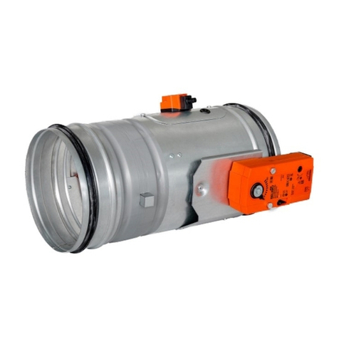
SMAY KTM User manual

a
v
https: //
www.smay.eu
Installation manual
KTM
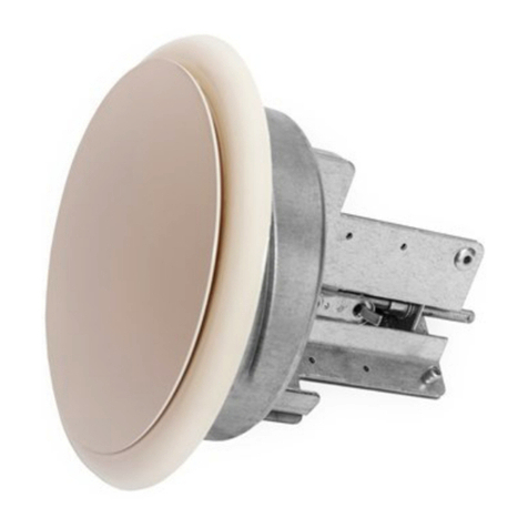
Fire Damper –round

Version 6.00
Date of editing: 15.09.2022 r.
Page 1 of 10
Installation manual
KTM
Version 6.00
SMAY reserves the right to make changes to this document.
TABLE OF CONTENT
INSTALLATION TECHNOLOGY.......................................................................................... 2
I. INSTALLATION TECHNOLOGY - CEILING............................................................... 3
II. INSTALLATION TECHNOLOGY –RIGID WALL......................................................... 4
III. INSTALLATION TECHNOLOGY –FLEXIBLE WALL .................................................... 6
IV. INSTALLATION TECHNOLOGY –WALL AND CEILING STRUCTURESS OF GREAT
THICKNESS ...................................................................................................... 9
V. INSTALLATION TECHNOLOGY –MONTAGE AWAY FROM RIGID WALL (SILICATE
BOARDS).......................................................................................................... 9
VI. CONNECTION DIAGRAM OF LIMIT SWITCHES IN THE KTM DAMPER ....................... 10

Version 6.00
Date of editing: 15.09.2022 r.
Page 2 of 10
Installation manual
KTM
INSTALLATION TECHNOLOGY
Before installing the fire dampers, make sure that there are no damage, during transport or storage, that could block
the baffle.
Check that the baffle can be opened and closed (full opening and closing position). To open fire dampers KTM use the
actuator key.
The opening and closing must proceed smoothly (not stepwise).
Do not pull by baffle to open or close fire damper, it may cause permanent damage, not covered by the warranty.
During KTM damper test, with size DN>125, while opening baffle, fold back the bumper (as shown on the fig. 5) so as
to unlock the bolt caught on it, allowing free rotation of the baffle.
Figure 1. KTM baffle opening method
Before installing, secure the fire damper, by dust and dirt, using a foil or other screening material. It can prevent
components of fire damper by damage.
Dampers to preserve of the declared resistance, insulation and smoke leakage EIS120, EIS90, EIS60, EIS30, should
be installed on wall, which was classified as EIS120, EIS90, EIS60, EIS30.
It is allowed to install KTM dampers in wall with other fire-resistance, should be remembered that fire-resistance in
this situation is resistance of lowest classified (in this regard) element in this system.
Ducts made of flammable and non-flammable materials can be connected to the damper. Ducts should be installed
that they cannot load the damper during fire. Ducts lengthening during fire can be compensated by support and knee.
ATTENTION: Distance between fire dampers or fire damper and construction elements must be:
a) min. 10 mm between fire damper, which are installed in different ventilating wires,
b) min. 10 mm between fire damper and construction element (wall/ceiling).
Version 6.00
Date of editing: 15.09.2022 r.
Page 3 of 10
Installation manual
KTM
I. INSTALLATION TECHNOLOGY - CEILING
a. Make an opening in the ceiling with the 40 [mm] (acceptable 40 ÷ 80 [mm]) greater than the nominal
dimensions of the fire damper: DN+40.
a. Put the closed fire damper into the installation opening and support or suspend, in this way that an axis of the
fire baffle matches the axis of the ceiling, and ensure a concentricity of fire damper and installation opening.
b. After setting the fire damper as described, fill the gap between the fire damper and the ceiling with cement,
cement-lime mortar or concrete.
c. After the mortar has dried (about 48 hours), remove the supports or suspension, check the fire damper correct
operation and leave it in open position (installing in KTM damper thermal fuse as shown on the fig. 6).
Figure 2. Thermal fuse installation method
Figure 3. Installation of KTM fire dampers in ceiling

Version 6.00
Date of editing: 15.09.2022 r.
Page 4 of 10
Installation manual
KTM
Figure 4. Installation of KTM fire dampers in ceiling
II. INSTALLATION TECHNOLOGY –RIGID WALL
a. Make an opening in the wall with the 40 [mm] (acceptable 40 ÷ 80 [mm]) greater than the nominal dimensions
of the fire damper: DN+40.
b. Put the closed fire damper into the installation opening and support or suspend, in this way that an axis of the
fire baffle matches the axis of the wall, and ensure a concentricity of fire damper and installation opening.
c. After setting the fire damper as described, fill the gap between the fire damper and the wall with cement,
cement-lime mortar or concrete.
d. After the mortar has dried (about 48 hours), remove the supports or suspensions, check the fire damper correct
operation and leave it in open position (installing in KTM damper thermal fuse as shown on the fig. 6).
Figure 5. Installation of KTM fire dampers in rigid wall with 115 mm thickness

Version 6.00
Date of editing: 15.09.2022 r.
Page 5 of 10
Installation manual
KTM
Figure 6. Installation of KTM fire dampers in rigid wall with horizontal rotation axis of baffle
Figure 7. Installation of KTM fire dampers in rigid wall with vertical rotation axis of baffle

Version 6.00
Date of editing: 15.09.2022 r.
Page 6 of 10
Installation manual
KTM
III. INSTALLATION TECHNOLOGY –FLEXIBLE WALL
a. Make an opening in the wall with the 40 [mm] (acceptable 40 ÷ 80 [mm]) greater than the nominal dimensions
of the fire damper: B=DN+40 and H=DN+40.
b. Make a frame of two layers of GKF boards, 12,5 mm thick and the width relative to the width of opening,
mounting by screws remembering to carefully seal the contact edges with a mastic: Hilti Firestop Coating CP 673,
Promastop-Coating, Promaseal-Mastic or Soudal Firesilicone B1 FR.
c. Put the closed fire damper into the installation opening and support or suspend, in this way that an axis of the
fire baffle matches the axis of the wall, and ensure a concentricity of fire damper and installation opening.
d. After setting the fire damper as described, fill the gap between the fire damper and the wall with non-flammable
mineral wool of high density, 100 kg/m3 or more.
e. Seal the place of filling with mineral wool using the sealing compounds Hilti Firestop Coating CP 673, Promastop-
Coating, Promaseal-Mastic or Soudal Firesilicone B1 FR.
f. Mount collar, both side of wall, made of GKF boards, 12,5 mm thick and DN+ 200 mm wide, using screws (with
a cut hole for the damper). For easy assembly, the collar can be made of two parts.
g. After mounting the collar, remove the supports or suspension, check the fire damper correct operation and leave
it in open position (installing in KTM damper thermal fuse as shown on the fig. 12).
Figure 8. Installation method of fire dampers KTM in flexible wall with 75 mm thickness

Version 6.00
Date of editing: 15.09.2022 r.
Page 7 of 10
Installation manual
KTM
Figure 9. Installation method of fire dampers KTM in flexible wall with 100 mm thickness
Figure 10. Installation method of fire dampers KTM in flexible wall with horizontal rotation axis of baffle

Version 6.00
Date of editing: 15.09.2022 r.
Page 8 of 10
Installation manual
KTM
Figure 11. Installation method of fire dampers KTM in flexible wall with vertical rotation axis of baffle
Figure 12. Installation method of fire dampers KTM in flexible wall with 125 mm thickness

Version 6.00
Date of editing: 15.09.2022 r.
Page 9 of 10
Installation manual
KTM
IV. INSTALLATION TECHNOLOGY –WALL AND CEILING STRUCTURESS OF GREAT
THICKNESS
Figure 13. Installation method of fire dampers KTM in structures thicker than 150 mm
In rigid and flexible wall construction and in ceiling with thickness less or equal to 150 mm, KTM fire dampers are
mounted in such a way that the damper baffle axis coincides with the axis of the wall or ceiling.
Whereas in case of walls and ceilings with thickness higher than 150 mm: the KTM fire dampers are mounted in such a
way, that the damper installation limit i.e. 125 mm, is maintained (as in figure 17).
V. INSTALLATION TECHNOLOGY –MONTAGE AWAY FROM RIGID WALL (SILICATE
BOARDS)
a. Make an opening in the wall with the dimensions 100 [mm] greater than the nominal dimensions of the fire
damper DN+100.
b. Push the ventilation duct into the installation opening and support or suspend it so that the channel and opening
alignment are maintained.
c. Install the closed damper to the ventilation duct, additionally support or suspend it.
d. On the mineral wool coverage section, apply 1mm PROMASTOP Coating (made by PROMAT) layer.
e. The PROMASTOP Coating layer has to be applied on fire barrier in the place where the wool was sealed on both
sides, with a size about DN + 300.
f. Wrap the ventilation duct and the damper at the appropriate length of mineral wool with high density at least
100 kg/m3.
g. When the mineral wool is mounted, check correct functionality of the damper, then leave it in the open position.

Version 6.00
Date of editing: 15.09.2022 r.
Page 10 of 10
Installation manual
KTM
Figure 14. Installation method of KTM fire dampers away from wall construction.
VI. CONNECTION DIAGRAM OF LIMIT SWITCHES IN THE KTM DAMPER
Microswitches D2SW-3L2M ( OMRON ) are used in KTM fire dampers as limit switches to signal the baffle
position. By the microswitch it is possible to connect two circuits, normally closed and normally open (closing only at
the moment of contact with baffle),
Figure 15. Connection diagram of D2SW-3L2M limit switches
Table of contents
Other SMAY Fire And Smoke Damper manuals
Popular Fire And Smoke Damper manuals by other brands

Exodraft
Exodraft SVD quick guide

CARNES
CARNES EFOA Installation, operation and maintenance instructions

Mandik
Mandik FDML Technical documentation

Tamco
Tamco AIR-IQ2 Installation guidelines

aldes
aldes CF1 Installation, operation and maintenance manual

System air
System air SAVE VTC 700 Replacement instructions