manuals.online logo
Brands
  1. Home
  2. •
  3. Brands
  4. •
  5. SMC Networks
  6. •
  7. Control Unit
  8. •
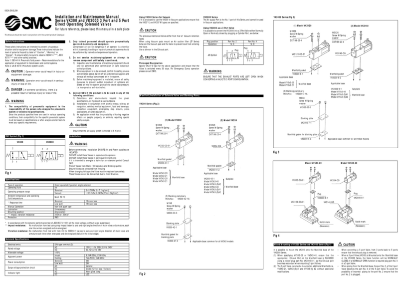
  9. SMC Networks SZ3000 Series User manual

SMC Networks SZ3000 Series User manual

This manual suits for next models

7

Other SMC Networks Control Unit manuals
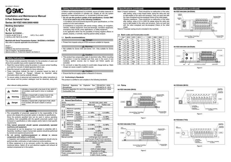
SMC Networks VQC4000 User manual

SMC Networks

SMC Networks VQC4000 User manual

SMC Networks XLS Series User manual

SMC Networks

SMC Networks XLS Series User manual

SMC Networks VHS20 Series User manual

SMC Networks

SMC Networks VHS20 Series User manual

SMC Networks VJ100 Manual

SMC Networks

SMC Networks VJ100 Manual

SMC Networks XGTP31-50336 Series User manual

SMC Networks

SMC Networks XGTP31-50336 Series User manual

SMC Networks EX12 SMJ1 Series User manual

SMC Networks

SMC Networks EX12 SMJ1 Series User manual

SMC Networks DXT1215 User manual

SMC Networks

SMC Networks DXT1215 User manual

SMC Networks VDW 10 Manual

SMC Networks

SMC Networks VDW 10 Manual

SMC Networks VQD1000 Series User manual

SMC Networks

SMC Networks VQD1000 Series User manual

SMC Networks VR51 Manual

SMC Networks

SMC Networks VR51 Manual

SMC Networks 56-VQC1000 Series Manual

SMC Networks

SMC Networks 56-VQC1000 Series Manual
SMC Networks JSY1000-E Series User manual
SMC Networks

SMC Networks JSY1000-E Series User manual

SMC Networks VV100 Series Manual

SMC Networks

SMC Networks VV100 Series Manual

SMC Networks EX430-SIL1 User manual

SMC Networks

SMC Networks EX430-SIL1 User manual

SMC Networks VF1000 Series Manual

SMC Networks

SMC Networks VF1000 Series Manual

SMC Networks VV100 Series User manual

SMC Networks

SMC Networks VV100 Series User manual

SMC Networks KE Series User manual

SMC Networks

SMC Networks KE Series User manual

SMC Networks SY3000 SERIES User manual

SMC Networks

SMC Networks SY3000 SERIES User manual

SMC Networks XLA Series User manual

SMC Networks

SMC Networks XLA Series User manual

SMC Networks EX180 Series User manual

SMC Networks

SMC Networks EX180 Series User manual

SMC Networks ASP Series User manual

SMC Networks

SMC Networks ASP Series User manual

SMC Networks AV2000-02-1 User manual

SMC Networks

SMC Networks AV2000-02-1 User manual

SMC Networks EX260-SDN1 Instruction Manual

SMC Networks

SMC Networks EX260-SDN1 Instruction Manual

SMC Networks EX600-SDN Series User manual

SMC Networks

SMC Networks EX600-SDN Series User manual

Popular Control Unit manuals by other brands

Seitz 14A80 user manual

Seitz

Seitz 14A80 user manual

Wilo RS485 Installation and operating instructions

Wilo

Wilo RS485 Installation and operating instructions

Becker CentralControl CC41 Commissioning Instruction

Becker

Becker CentralControl CC41 Commissioning Instruction

SICK CDB650 operating instructions

SICK

SICK CDB650 operating instructions

Panduit NetKey NKP5E88M Series installation instructions

Panduit

Panduit NetKey NKP5E88M Series installation instructions

MX Options Concentric Petite Fitting instructions

MX

MX Options Concentric Petite Fitting instructions

Clean Water Systems Fleck 2510 Installation & start?up guide

Clean Water Systems

Clean Water Systems Fleck 2510 Installation & start?up guide

Fairchild FSB44104A user guide

Fairchild

Fairchild FSB44104A user guide

LEGRAND Wattstopper LMIN-104 installation instructions

LEGRAND

LEGRAND Wattstopper LMIN-104 installation instructions

PMK ATT10BNCS instruction manual

PMK

PMK ATT10BNCS instruction manual

Tektronix TDS3FFT user manual

Tektronix

Tektronix TDS3FFT user manual

Woodward easYgen Technical manual

Woodward

Woodward easYgen Technical manual

Balluff BNI EIP-502-105-R015 user guide

Balluff

Balluff BNI EIP-502-105-R015 user guide

NXP Semiconductors TWR-LS1021A Getting started

NXP Semiconductors

NXP Semiconductors TWR-LS1021A Getting started

Advantech PCM-3117 Startup manual

Advantech

Advantech PCM-3117 Startup manual

Danfoss MCO 101 manual

Danfoss

Danfoss MCO 101 manual

Moons' Lin Engineering R701P user manual

Moons'

Moons' Lin Engineering R701P user manual

Aventics RV1 operating instructions

Aventics

Aventics RV1 operating instructions

manuals.online logo
manuals.online logoBrands
  • About & Mission
  • Contact us
  • Privacy Policy
  • Terms and Conditions

Copyright 2025 Manuals.Online. All Rights Reserved.

Series SZ3000
5 Port Solenoid Valve
FREELOCK
FREE
LOCK
Cassette Type Manifold
P. 558
P. 577
P. 584
P. 588
Plug-in Type
Non Plug-in Type
EX140/Serial transmission system
EX510/Serial transmission system
LOCKFREE
6
15
14
7
0
1
COM
PWB
LOCK FREE
Rubber Seal
Series
Height
Weight
SZ3000
31% reduction
12% reduction
A plug-in manifold has been created with a height of 43.5
mm (including DIN rail). Valve replacement can be
performed easily. Moreover, since spare terminates for
wiring (receptacle housings) are contained inside the
manifold, terminal changes (additions) can be performed
quickly and easily. (The number of additional stations is
limited by the manifold specifications. For details, refer to
page 571.)
Adjustment and maintenance of
equipment can be performed with
greater safety, since the power to
each valve can be shut off
individually with built-in switches.
The plug-in cassette system
makes valve replacement easy.
Valves equipped with
switches
High speed response of 10 ms
SZ3000 double, 0.5 MPa
24 VDC, Without surge voltage suppressor
Low power consumption and a faster response time of 10
ms are obtained with a unique pilot valve construction.
Low power consumption: 0.6 W
(Current draw: 25 mA at 24 VDC)
Low power consumption enables direct operation by a
PLC. Cost savings are realized through the use of a
smaller power supply and the elimination of relay cards.
Easy attaching/detaching of the tubing
The interval between ports A and B is a wide 20.5 mm, allowing
easy changes of fittings and tubing.
C4/C6 One-touch fitting C4/C6
One-touch fitting
(Elbow type)
A port
B port
M5 port block assembly
(Compared with SX3000-45
with DIN rail manifold and 5
stations)
Size and weight reduced by
eliminating the manifold base
High reliability and long service life
exceeding 50 million cycles or more
High reliability and long service life have been achieved with
guide ring construction which prevents eccentricity of the
main valve, and a return piston with increased return force.
(Single and double solenoid type)
The connector entry direction can be
changed from top to side with a simple
operation.
Switch for locking a connector
557
SJ
SY
SV
SYJ
SZ
VP4
S0700
VQ
VQ4
VQ5
VQC
VQZ
SQ
VFS
VFR
VQ7
P0557-P0608-E.qxd 08.9.1 2:36 PM Page 557
Courtesy of Steven Engineering, Inc.-230 Ryan Way, South San Francisco, CA 94080-6370-Main Office: (650) 588-9200-Outside Local Area: (800) 258-9200-www.stevenengineering.com
LOCK FREE
LOCK FREE
LOCK FREE
LOCK FREE
LOCK FREE
LOCK FREE
SS5Z3 60 FUPD105
Pilot type
Power supply terminals
Valve stations
Internal pilot
External pilot
Nil
R
SUP/EXH block fitting specifications
Straight
Elbow fittings (Upward)
Elbow fittings (Downward)
Nil
L
B
Specifications
24 VDC, Positive common
12 VDC, Positive common
24 VDC, Negative common
12 VDC, Negative common
Symbol
P
P12
N
N12
Connector mounting position
Symbol
D
Mounting position
D side
SUP/EXH block mounting
position
U
D
B
M
*
U side (2 to 10 stations)
D side (2 to 10 stations)
Both sides (2 to 20 stations)
Special specifications
CE-compliant
—
CE-compliant
Nil
Q
Connector type
F:D-sub connector
(25 pins)
P: Flat ribbon cable
(26 pins)
PG: Flat ribbon cable
(20 pins)
PH: Flat ribbon cable
(10 pins)
Connector entry direction
1: Perpendicular connector 2: Lateral connector
Option
When a longer DIN rail is
desired than the specified
stations, specify the station
number to be required.
*
For special specifications,
indicate separately by the
manifold specification sheet.
Note) A total of up to 3 SUP/EXH
blocks can be mounted.
Please contact SMC if 4 or
more will be mounted.
F: D-sub connector
Note
Symbol
02
10
02
20
P: Flat ribbon cable connector (26 pins)
Note
Symbol
02
11
02
20
PG: Flat ribbon cable connector (20 pins)
PH: Flat ribbon cable connector (10 pins)
Note
Symbol
02
08
02
16
Note
Symbol
02
04
02
08
Stations
2 stations
10 stations
2 stations
20 stations
Stations
2 stations
11 stations
2 stations
20 stations
Stations
2 stations
8 stations
2 stations
16 stations
Stations
2 stations
4 stations
2 stations
8 stations
Double wiring specifications (1)
Specified layout (2)
(Up to 21 solenoids possible)
Double wiring specifications
Specified layout
(Up to 22 solenoids possible)
Double wiring specifications
Specified layout
(Up to 8 solenoids possible)
Double wiring specifications
Specified layout
(Up to 16 solenoids possible)
Note 1) Double wiring specifications: Single, double, 3 position and 4 position solenoid
valves can be used at all of the manifold stations.
Note 2) Specified layout: Indicate wiring specifications on a manifold specification sheet.
(Please note that in locations where single solenoid wiring is indicated, it will be
impossible to use double or 3 position/4 position valves.)
558
5 Port Solenoid Valve
Series SZ3000
Plug-in Type
How to Order
Plug-in manifold with power supply terminals
P0557-P0608-E.qxd 08.9.1 2:36 PM Page 558
Courtesy of Steven Engineering, Inc.-230 Ryan Way, South San Francisco, CA 94080-6370-Main Office: (650) 588-9200-Outside Local Area: (800) 258-9200-www.stevenengineering.com
LOCK FREE
LOCK FREE
LOCK FREE
LOCK FREE
LOCK FREE
LOCK FREE
FUD105
Plug-in manifold without power supply terminals
Option
Pilot type
Valve stations
Internal pilot
External pilot
Nil
R
SUP/EXH block fitting specifications
Straight
Elbow fittings (Upward)
Elbow fittings (Downward)
Nil
L
B
CE-compliant
—
CE-compliant
Nil
Q
SS5Z3 60
Connector type
F:D-sub connector
(25 pins)
P: Flat ribbon cable
(26 pins)
PG: Flat ribbon cable
(20 pins)
PH: Flat ribbon cable
(10 pins)
Connector mounting position
Symbol
D
Mounting position
D side
Connector entry direction
1: Perpendicular connector 2: Lateral connector
SUP/EXH block mounting
position
U
D
B
M∗
U side (2 to 10 stations)
D side (2 to 10 stations)
Both sides (2 to 20 stations)
Special specifications
F: D-sub connector
Note
Symbol
02
12
02
20
P: Flat ribbon cable connector (26 pins)
Note
Symbol
02
12
02
20
PG: Flat ribbon cable connector (20 pins)
PH: Flat ribbon cable connector (10 pins)
Note
Symbol
02
09
02
19
Note
Symbol
02
04
02
09
Stations
2 stations
12 stations
2 stations
20 stations
Stations
2 stations
12 stations
2 stations
20 stations
Stations
2 stations
9 stations
2 stations
19 stations
Stations
2 stations
4 stations
2 stations
9 stations
Double wiring specifications (1)
Specified layout (2)
(Up to 24 solenoids possible)
Double wiring specifications
Specified layout
(Up to 25 solenoids possible)
Double wiring specifications
Specified layout
(Up to 9 solenoids possible)
Double wiring specifications
Specified layout
(Up to 19 solenoids possible)
Note 1) Double wiring specifications: Single, double, 3 position and 4 position solenoid
valves can be used at all of the manifold stations.
Note 2) Specified layout: Indicate wiring specifications on a manifold specification sheet.
(Please note that in locations where single solenoid wiring is indicated, it will be
impossible to use double or 3 position/4 position valves.)
When a longer DIN rail is desired
than the specified stations,
specify the station number to be
required.
559
Cassette Type Manifold
Series SZ3000
How to Order
∗For special specifications,
indicate separately by the
manifold specification sheet.
Note) A total of up to 3 SUP/EXH
blocks can be mounted.
Please contact SMC if 4 or
more will be mounted.
SJ
SY
SV
SYJ
SZ
VP4
S0700
VQ
VQ4
VQ5
VQC
VQZ
SQ
VFS
VFR
VQ7
P0557-P0608-E.qxd 08.9.1 2:36 PM Page 559
Courtesy of Steven Engineering, Inc.-230 Ryan Way, South San Francisco, CA 94080-6370-Main Office: (650) 588-9200-Outside Local Area: (800) 258-9200-www.stevenengineering.com
Nil:Without switch
J:With switch
SZ3 51 C6LOZ
60
Type of actuation
1
2
3
4
5
A
C
Rated voltage
5
6
24 VDC
12 VDC
Pilot type
Internal pilot
External pilot
Nil
R
Common specifications
Rated voltage
Positive common
Negative common
Nil
N
When using on a
manifold with power
supply terminals, be
sure to match with
the manifold’s voltage
specifications.
Manual override
Back pressure check valve
None
Built-in
Nil
K
B
(A)
4
(B)
2
5
(EA)
1
(P)
3
(EB)
(A)
4
(B)
2
5
(EA)
1
(P)
3
(EB)
(A)
4
(B)
2
5
(EA)
1
(P)
3
(EB)
(A)
4
(B)
2
5
(EA)
1
(P)
3
(EB)
(A)
4
(A)
4
(A)
4
(A)
4
(B)
2
(B)
2
(B)
2
(B)
2
5
(EA)
1
(P)
3
(EB)
5
(R)
5
(R)
5
(R)
1
(P)
1
(P)
1
(P)
SOL.bSOL.a 3
(R)
3
(R)
3
(R)
SOL.bSOL.a
SOL.bSOL.a
A, B port size
M5: M5 x 0.5
A4
B2
A4
B2
A4
B2
A4
B
2
CE-compliant
—
CE-compliant
Nil
Q
Mede to Order
—
Main Valve Fluoro Rubber Specifications
(Refer to page 592)
Nil
X90
SMC
OFF
ON
2 position single solenoid
2 position double solenoid
3 position closed center
3 position exhaust center
3 position pressure center
4 position dual 3 port valve: N.C./N.C.
4 position dual 3 port valve: N.O./N.O.
4 position dual 3 port valve: N.C./N.O.
The built-in back pressure
check valve type has an ef-
fective area approximately
20% smaller.
The 3 position valve is not
available with back pressure
check valve.
The 4 position dual 3 port
valve is not available with
external pilot specifications.
When using on a manifold
with power supply terminals,
be sure to match with the
manifold’s common specifi-
cations.
∗For switch opera-
tion, refer to page
593.
C4:One-touch fitting for ø4
C6:One-touch fitting for ø6
Elbow fitting assembly (Upward)
L4:ø4 elbow fitting assembly
L6:ø6 elbow fitting assembly
Elbow fitting assembly (Downward)
B4:ø4 elbow fitting assembly
B6:ø6 elbow fitting assembly
Nil:Non-locking
push type
D:Push-turn locking
slotted type
560
Series SZ3000
How to Order
How to order solenoid valves For plug-in (Common for both with and without power supply terminals)
P0557-P0608-E.qxd 08.9.1 2:36 PM Page 560
Courtesy of Steven Engineering, Inc.-230 Ryan Way, South San Francisco, CA 94080-6370-Main Office: (650) 588-9200-Outside Local Area: (800) 258-9200-www.stevenengineering.com
LOCK FREE
1 2 3
Model
+ COM, – COM
D-sub connector
Type 60F
Flat ribbon cable type 60P
Type 60P
Plug-in type
Common SUP, EXH
Valve
Lateral, Upward, Downward
C8
C4, C6, M5
Type 60PG Type 60PH
Manifold Specifications
Flow Characteristics
W = 3.2n1 + 53n2 + m + 126.5
Port size Flow characteristics
Cvb Cvb
1, 5, 3
(P, EA, EB)
4, 2
(A, B)
C4
C8 C6
M5
SS5Z3-60PD2-05U-P ·················· 1 set (Manifold part number)
∗ SZ3160-5LOZ-C6 ························ 2 sets (Single solenoid part no.)
∗ SZ3260-5LOZ-C6 ························ 3 sets (Double solenoid part no.)
The asterisk denotes the symbol for assembly. Prefix it to the part nos.
of the solenoid valve, etc.
Cassette Type Manifold
Series SZ3000
Stations are counted from D side as the 1st one. Indicate the valves to be
attached below the manifold part number, in order starting from station 1 as
shown in the drawing. When entry of part numbers becomes complicated,
indicate on the manifold specification sheet.
4 (A), 2 (B) port
Porting specification
Port size
Applicable connector
Internal wiring
Weight W (g) (2)
n1: Stations
n2:
Number of SUP/EXH blocks
m: Weight of DIN rail
Location
Direction
1 (P), 3/5 (R) port
4 (A), 2 (B) port
Manifold
1 (P: SUP), 3/5 (R: EXH) system
Valve stations (With power terminal)
D-sub connector
Conforming to
MIL-C-24308
JIS-X-5101
Flat ribbon cable connector
Socket: 26 pins MIL type
with strain relief
Conforming to MIL-C-83503
Flat ribbon cable connector
Socket: 20 pins MIL type
with strain relief
Conforming to MIL-C-83503
Flat ribbon cable connector
Socket: 10 pins MIL type
with strain relief
Conforming to MIL-C-83503
2 to 20 stations 2 to 16 stations 2 to 8 stations
Note 1) In cases such as those where many valves are operated simultaneously, use type B (double side
SUP/EXH), applying pressure to the 1(P) ports on both sides and exhausting from the 3(R) ports on
both sides.
Note 2) The weight W is the value for the D-sub connector manifold with power supply terminals only. To obtain
the weight with solenoid valves attached, add the solenoid valve weights given on page 562 for the
appropriate number of stations. For DIN rail weight, refer to page 564.
Note) • The value is for manifold base with 5 stations and individually operated 2 position type.
• Values inside [ ] are for 4 position dual 3 port valves.
561
Made to Order
(Refer to page 592 for details.)
Double solenoid (24 VDC)
SZ3260-5LOZ-C6 (3 sets)
Single solenoid (24 VDC)
SZ3160-5LOZ-C6 (2 sets)
With power supply terminals
Plug-in manifold
SS5Z3-60PD2-05U-P
SUP/EXH block (U side mounting)
D side
Stations
U side
How to Order Valve Manifold Assembly
Ordering example (SZ3000, positive common with power supply terminals)
SJ
SY
SV
SYJ
SZ
VP4
S0700
VQ
VQ4
VQ5
VQC
VQZ
SQ
VFS
VFR
VQ7
P0557-P0608-E.qxd 08.9.1 2:36 PM Page 561
Courtesy of Steven Engineering, Inc.-230 Ryan Way, South San Francisco, CA 94080-6370-Main Office: (650) 588-9200-Outside Local Area: (800) 258-9200-www.stevenengineering.com
Air
0.15 to 0.7
0.1 to 0.7
0.2 to 0.7
0.15 to 0.7
–100 kPa to 0.7
0.25 to 0.7
0.25 to 0.7
0.25 to 0.7
–10 to 50 (No freezing. Refer to page 5.)
3
Non-locking push type, Push-turn locking slotted type
Common exhaust type for main and pilot valve
Not required
Unrestricted
150/30
Dust-protected
SZ3000Series
Solenoid Specifications
L type (For plug-in), M type plug connector (M)
24, 12, 6, 5, 3 VDC
±10% of rated voltage
0.6 (With light: 0.65)
Diode
LED
Electrical entry
Weight
Response Time
Type of actuation
Response time (ms) (at the pressure of 0.5 MPa)
Valve model Type of actuation Port size
4(A), 2(B)
SZ360--C4
SZ360--C6
SZ360--M5
Mass (g)
78
84
88
84
74
81
85
81
69
75
79
75
10
Solenoid Valve Specifications
Fluid
2 position single
2 position double
3 position
4 position dual 3 port valve
2 position single
2 position double
3 position
2 position single, double
4 position dual 3 port valve
3 position
Internal pilot
operating
pressure range
(MPa)
External pilot
operating
pressure range
(MPa)
Pilot
pressure
range
Operating pressure range
Ambient and fluid temperature (°C)
Max. operating
frequency (Hz)
Manual override (Manual operation)
Pilot type
Lubrication
Mounting orientation
Impact/Vibration resistance m/s2Note)
Enclosure
Note) Impact resistance: No malfunction occurred when it is tested with a drop tester in the axial direction
and at the right angles to the main valve and armature in both energized and de-
energized states every once for each condition. (Values at the initial period)
Vibration resistance: No malfunction occurred in a one-sweep test between 45 and 2000 Hz. Test was
performed at both energized and de-energized states in the axial direction and
at the right angles to the main valve and armature. (Values at the initial period)
Rated coil voltage (V) Note)
Allowable voltage fluctuation
Power consumption (W)
Surge voltage suppressor
Indicator light
Note) Only 24 VDC and 12 VDC are available for plug-in use.
Note) Based on dynamic performance test, JIS B 8375-1981. (Coil temperature: 20°C, at rated voltage)
2 position single
2 position double
3 position
4 position dual 3 port valve
12 or less
10 or less
15 or less
30 or less
Without surge voltage
suppressor
With surge voltage suppressor
S, Z type
15 or less
13 or less
20 or less
35 or less
M5 x 0.8
2 position
3 position
4 position
4 position
4 position
2 position
3 position
2 position
3 position
Single
Double
Closed center
Exhaust center
Pressure center
Dual 3 port valve
Single
Double
Closed center
Exhaust center
Pressure center
Dual 3 port valve
Single
Double
Closed center
Exhaust center
Pressure center
Dual 3 port valve
C4
One-touch fitting
for ø4
C6
One-touch fitting
for ø6
562
Series SZ3000
P0557-P0608-E.qxd 08.9.1 2:36 PM Page 562
Courtesy of Steven Engineering, Inc.-230 Ryan Way, South San Francisco, CA 94080-6370-Main Office: (650) 588-9200-Outside Local Area: (800) 258-9200-www.stevenengineering.com
Series
SZ3000
Part no.
SZ3000-114-4A
Manifold Option
SZ3000-155-1A
Applicable fittings
size
ød
4
6
8
KQ2P-04
KQ2P-06
KQ2P-08
Model AL D
16
18
20.5
32
35
39
6
8
10
Dimensions
øD
L
A
ød
Series
SZ3000
Part no.
SZ3000-114-4A
Series
SZ3000 (ø8)
Model
AN203-KM8
Effective area
14 mm2
B
26
C
51
A
ø16
A
C
B
Series
SZ3000
Part no.
SZ3000-114-2A
FREE
LOCK
BA
BA
A
A
A
SUP block disk
EXH block disk
Label for block disk
Silencer with One-touch fitting
Plug (White)
Label for EXH block disk
Label for SUP/EXH block disk
By installing a SUP block disk in the pressure supply passage of a
manifold valve, it is possible to supply two or more different high and low
pressures to one manifold. (Use in combination with a pilot port block
disk.)
Blanking block assembly
SZ3000-55-1A
These are mounted when later addition of valves is planned, etc.
The labels shown below are used on manifold stations containing
SUP/EXH block disk(s) to show their location. (3 pcs. each)
These are inserted in cylinder ports or SUP/EXH ports which are not
being used.
Purchasing order is available in units of 10 pieces.
This silencer can be mounted on the manifolds’ port R (exhaust) with
a single touch.
By installing an EXH block disk in the exhaust passage of a manifold
valve, it is possible to divide the valve’s exhaust so that it does not affect
another valve. (Two block disks are needed to divide both exhausts.)
Label for SUP block disk Label for pilot port block disk
Pilot port block disk
By installing a pilot port block disk in the pilot passage of a manifold
valve, it can be function as an internal pilot/external pilot mixed
manifold.
∗When a block disk is concurrently ordered by specifying on the manifold specification
sheet, etc., a label will be stuck on the position where block disk is mounted.
563
Cassette Type Manifold
Series SZ3000
SJ
SY
SV
SYJ
SZ
VP4
S0700
VQ
VQ4
VQ5
VQC
VQZ
SQ
VFS
VFR
VQ7
P0557-P0608-E.qxd 08.9.1 2:36 PM Page 563
Courtesy of Steven Engineering, Inc.-230 Ryan Way, South San Francisco, CA 94080-6370-Main Office: (650) 588-9200-Outside Local Area: (800) 258-9200-www.stevenengineering.com
AXT100-DS25-015
030
050
AXT100-FC-1
3
to
Cable
length (L)Assmbly part no.
AXT100-DS25-015
AXT100-DS25-030
AXT100-DS25-050
1.5 m
3 m
5 m
Note
Cable 25 cores
x 24AWG
Cable length (L)
1.5 m
3 m
5 m
Connector width (W)
10 pins
AXT100-FC10-1
AXT100-FC10-2
AXT100-FC10-3
17.2
20 pins
AXT100-FC20-1
AXT100-FC20-2
AXT100-FC20-3
30
26 pins
AXT100-FC26-1
AXT100-FC26-2
AXT100-FC26-3
37.5
Flat Ribbon Cable Assembly
Terminal no.
1
2
3
4
5
6
7
8
9
10
11
12
13
14
15
16
17
18
19
20
21
22
23
24
25
No.
L dimension
Mass (g)
0
98
17.6
1
110.5
19.9
2
123
22.1
3
135.5
24.4
4
148
26.6
5
160.5
28.9
6
173
31.1
7
185.5
33.4
8
198
35.6
9
210.5
37.9
No.
L dimension
Mass (g)
10
223
40.1
11
235.5
42.4
12
248
44.6
13
260.5
46.9
14
273
49.1
15
285.5
51.4
16
298
53.6
17
310.5
55.9
18
323
58.1
19
335.5
60.4
No.
L dimension
Mass (g)
20
348
62.6
21
360.5
64.9
22
373
67.1
23
385.5
69.4
24
398
71.6
25
410.5
73.9
26
423
76.1
27
435.5
78.4
28
448
80.6
29
460.5
82.9
VZ1000-11-1-
(7.5)
(25)
(35)
L
8
5.5
26 2
25 1
W
L
6
(15.6)
2 x M2.6 x 0.45
47.04
55
16
44
8
L
SMC
Manifold Option
D-sub connector (25 pins)/Cable assembly
DIN rail dimensions/Mass
Refer to the L dimension tables
∗Enter a number from the DIN rail dimension table below.
Rail mounting hole pitch 12.5
Flat ribbon cable type/Cable assembly
Triangle mark position
Terminal no.
Red
∗For other commercial connectors, use a type with strain relief conforming to
MIL-C-83503.
Connector manufacturers’ example
• Hirose Electric Co., Ltd.
• Sumitomo 3M Limited
• Fujitsu Limited
• Japan Aviation Electronics Industry, Ltd.
• J.S.T. Mfg. Co., Ltd.
Connector manufacturers’ example
• Hirose Electric Co., Ltd.
• Fujitsu Limited
• Japan Aviation Electronics Industry, Ltd.
• J.S.T. Mfg. Co., Ltd.
∗For other commercial connectors, use a 25 pins
type with female connector conforming to MIL-C-
24308.
D-sub Connector Cable
Assembly Electric
Characteristics
Item
Characteristics
65 or less
5 or less
Voltage limit
VAC, 1 min. 1000
Note) The minimum
bending radius for
D-sub connector
cables is 20 mm.
Lead wire color
Black
Brown
Red
Orange
Yellow
Pink
Blue
Purple
Gray
White
White
Yellow
Orange
Yellow
Pink
Blue
Purple
Gray
Orange
Red
Brown
Pink
Gray
Black
White
Dot marking
None
None
None
None
None
None
None
White
Black
Black
Red
Red
Red
Black
Black
White
None
None
Black
White
White
Red
Red
White
None
D-sub Connector Cable Assembly
Terminal No.
Multi-core vinyl cable
0.3 mm2 x 25C
Socket side
Terminal no.
564
Series SZ3000
P0557-P0608-E.qxd 08.9.1 2:36 PM Page 564
Courtesy of Steven Engineering, Inc.-230 Ryan Way, South San Francisco, CA 94080-6370-Main Office: (650) 588-9200-Outside Local Area: (800) 258-9200-www.stevenengineering.com
Positive common Negative common
13
12 25
Common
SOL.B
SOL.A
SOL.B
SOL.A
SOL.B
SOL.A
SOL.B
SOL.A
24
11
2
13
12 25
24
11 23
10
2
1
14
Positive pin (Common)
Negative pin
Positive pin (Common)
Negative pin
Power supply terminal
SOL.B
SOL.A
SOL.B
SOL.A
SOL.B
SOL.A
13
12 25
24
11 23
10
2
1
14
1515
Positive pin
Negative pin (Common)
Power supply terminal
SOL.B
SOL.A
SOL.B
SOL.A
SOL.B
SOL.A
15
14
1
24
26
23
25
Common
SOL.B
SOL.A
SOL.B
SOL.A
SOL.B
SOL.A
SOL.B
SOL.A
21
22
2
3
4
1
24
26
23
25
SOL.B
SOL.A
SOL.B
SOL.A
SOL.B
SOL.A
Triangle mark
21
22
2
3
4
1
Positive pin
Negative pin (Common)
Power supply terminal
24
26
23
25
SOL.B
SOL.A
SOL.B
SOL.A
SOL.B
SOL.A
21
22
2
3
4
1
Triangle mark Triangle mark
Without Power Supply Terminal With Power Supply Terminal
Type 60F D-sub Connector Type (25 pins)
Without Power Supply Terminal With Power Supply Terminal
Type 60P Flat Ribbon Cable Type (26 pins)
• The common polarity should be the same as the
common specifications of the valve to be used.
• The maximum number of stations that can be
accommodated is 20 manifold stations, with up to
24 solenoids. • The maximum number of stations that can be accommodated is 20 manifold stations, with up to 21 solenoids.
• The circuits above are for the double wiring specifications with up to 10 or 12 stations. Connect to SOL.A in the case of a single solenoid. Moreover, when wiring
instructions are given on a manifold specification sheet, the “A” signal for single and the “A, B” signals for double should be wired in order 1, 14, 2, 15......etc., without
skipping or leaving any connectors remaining.
• Stations are counted from D side as the 1st one.
• The common polarity should be the same as the
common specifications of the valve to be used.
• The maximum number of stations that can be
accommodated is 20 manifold stations, with up to
25 solenoids. • The maximum number of stations that can be accommodated is 20 manifold stations, with up to 22 solenoids.
• The circuits above are for the double wiring specifications with up to 11 or 12 stations. Connect to SOL.A in the case of a single solenoid. Moreover, when wiring
instructions are given on a manifold specification sheet, the “A” signal for single and the “A, B” signals for double should be wired in order 1, 2, 3, 4......etc., without
skipping or leaving any connectors remaining.
• Stations are counted from D side as the 1st one.
• Since terminal numbers are not indicated on the flat cable, use the triangle mark as a reference for wiring.
Station 12
Station 11
Station 2
Station 1
Light/Surge
voltage
suppressor
Light/Surge
voltage
suppressor
Light/Surge
voltage
suppressor
Light/Surge
voltage
suppressor
Light/Surge
voltage
suppressor
Light/Surge
voltage
suppressor
Light/Surge
voltage
suppressor
Light/Surge
voltage
suppressor
Light/Surge
voltage
suppressor
Light/Surge
voltage
suppressor
Light/Surge
voltage
suppressor
Light/Surge
voltage
suppressor
Light/Surge
voltage
suppressor
Light/Surge
voltage
suppressor
Light/Surge
voltage
suppressor
Light/Surge
voltage
suppressor
Light/Surge
voltage
suppressor
Light/Surge
voltage
suppressor
Light/Surge
voltage
suppressor
Light/Surge
voltage
suppressor
Light/Surge
voltage
suppressor
Light/Surge
voltage
suppressor
Light/Surge
voltage
suppressor
Light/Surge
voltage
suppressor
Station 12
Station 11
Station 2
Station 1
Station 10
Station 2
Station 1
Station 10
Station 2
Station 1
Station 11
Station 2
Station 1
Station 11
Station 2
Station 1
565
Cassette Type Manifold
Series SZ3000
Manifold Electrical Wiring
SJ
SY
SV
SYJ
SZ
VP4
S0700
VQ
VQ4
VQ5
VQC
VQZ
SQ
VFS
VFR
VQ7
P0557-P0608-E.qxd 08.9.1 2:36 PM Page 565
Courtesy of Steven Engineering, Inc.-230 Ryan Way, South San Francisco, CA 94080-6370-Main Office: (650) 588-9200-Outside Local Area: (800) 258-9200-www.stevenengineering.com
18
20
17
19
Common
SOL.B
SOL.A
SOL.B
SOL.A
SOL.B
SOL.A
SOL.B
SOL.A
15
16
2
3
4
1
10
9
Common
SOL.B
SOL.A
SOL.B
SOL.A
SOL.B
SOL.A
7
8
2
3
4
1
18
20
17
19
SOL.B
SOL.A
SOL.B
SOL.A
SOL.B
SOL.A
15
16
2
3
4
1
18
20
17
19
SOL.B
SOL.A
SOL.B
SOL.A
SOL.B
SOL.A
15
16
2
3
4
1
Triangle mark
Triangle mark
10
9
SOL.B
SOL.A
SOL.B
SOL.A
SOL.B
SOL.A
7
8
2
3
4
1
10
9
SOL.B
SOL.A
SOL.B
SOL.A
SOL.B
SOL.A
7
8
2
3
4
1
Type 60PH Flat Ribbon Cable Type (10 pins)
Positive common Negative common
Without Power Supply Terminal With Power Supply Terminal
• The common polarity should be the same as the
common specifications of the valve to be used.
• The maximum number of stations that can be
accommodated is 19 manifold stations, with up to
19 solenoids.
• The circuits above are for the double wiring specifications with up to 8 or 9 stations. Connect to SOL.A in the case of a single solenoid. Moreover, when wiring
instructions are given on a manifold specification sheet, the “A” signal for single and the “A, B” signals for double should be wired in order 1, 2, 3, 4......etc., without
skipping or leaving any connectors remaining.
• Stations are counted from D side as the 1st one.
• Since terminal numbers are not indicated on the flat cable, use the triangle mark as a reference for wiring.
• The maximum number of stations that can be accommodated is 16 manifold stations, with up to 16 solenoids.
• The common polarity should be the same as the
common specifications of the valve to be used.
• The maximum number of stations that can be
accommodated is 9 manifold stations, with up to 9
solenoids. • The maximum number of stations that can be accommodated is 8 manifold stations, with up to 8 solenoids.
• The circuits above are for the double wiring specifications with up to 4 stations. Connect to SOL.A in the case of a single solenoid. Moreover, when wiring instructions
are given on a manifold specification sheet, the “A” signal for single and the “A, B” signals for double should be wired in order 1, 2, 3, 4......etc., without skipping or
leaving any connectors remaining.
• Stations are counted from D side as the 1st one.
• Since terminal numbers are not indicated on the flat cable, use the triangle mark as a reference for wiring.
Positive pin
Negative pin (Common)
Positive pin (Common)
Negative pin
Positive pin
Negative pin (Common)
Positive pin (Common)
Negative pin
Power supply terminal Power supply terminal
Triangle mark Triangle mark
Power supply terminal Power supply terminal
Triangle mark Triangle mark
Station 8
Station 2
Station 1
Station 8
Station 2
Station 1
Station 9
Station 8
Station 2
Station 1
Station 4
Station 2
Station 1
Station 4
Station 2
Station 1
Station 4
Station 2
Station 1
Light/Surge
voltage
suppressor
Light/Surge
voltage
suppressor
Light/Surge
voltage
suppressor
Light/Surge
voltage
suppressor
Light/Surge
voltage
suppressor
Light/Surge
voltage
suppressor
Light/Surge
voltage
suppressor
Light/Surge
voltage
suppressor
Light/Surge
voltage
suppressor
Light/Surge
voltage
suppressor
Light/Surge
voltage
suppressor
Light/Surge
voltage
suppressor
Light/Surge
voltage
suppressor
Light/Surge
voltage
suppressor
Light/Surge
voltage
suppressor
Light/Surge
voltage
suppressor
Light/Surge
voltage
suppressor
Light/Surge
voltage
suppressor
Light/Surge
voltage
suppressor
Light/Surge
voltage
suppressor
Light/Surge
voltage
suppressor
Light/Surge
voltage
suppressor
Light/Surge
voltage
suppressor
Light/Surge
voltage
suppressor
566
Series SZ3000
Type 60PG Flat Ribbon Cable Type (20 pins)
Manifold Electrical Wiring
P0557-P0608-E.qxd 08.9.1 2:36 PM Page 566
Courtesy of Steven Engineering, Inc.-230 Ryan Way, South San Francisco, CA 94080-6370-Main Office: (650) 588-9200-Outside Local Area: (800) 258-9200-www.stevenengineering.com