manuals.online logo
Brands
  1. Home
  2. •
  3. Brands
  4. •
  5. SMC Networks
  6. •
  7. Control Unit
  8. •
  9. SMC Networks EX600-SPN4 User manual

SMC Networks EX600-SPN4 User manual

EX600-SMY122EN
Page 1 of 2
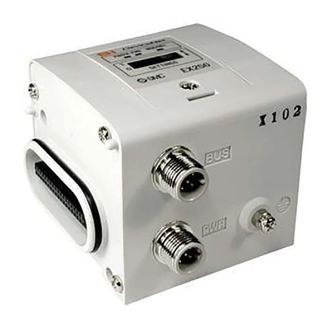
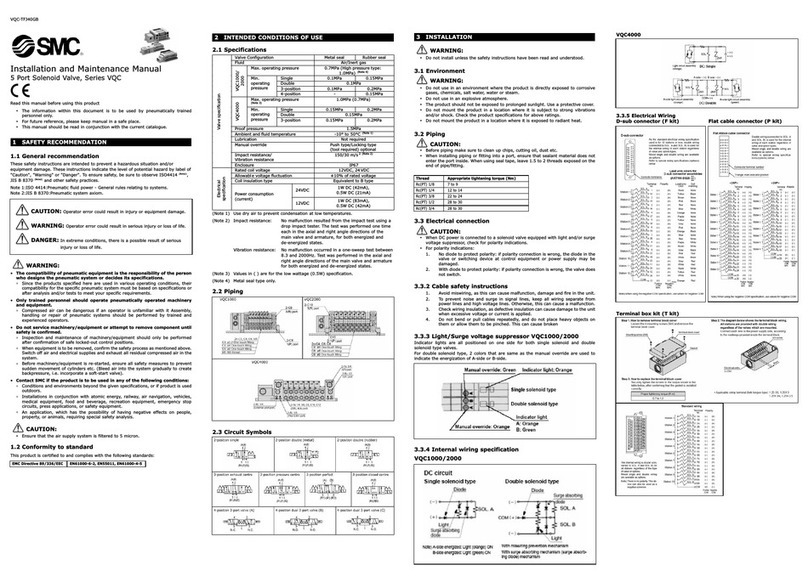
Instruction Manual
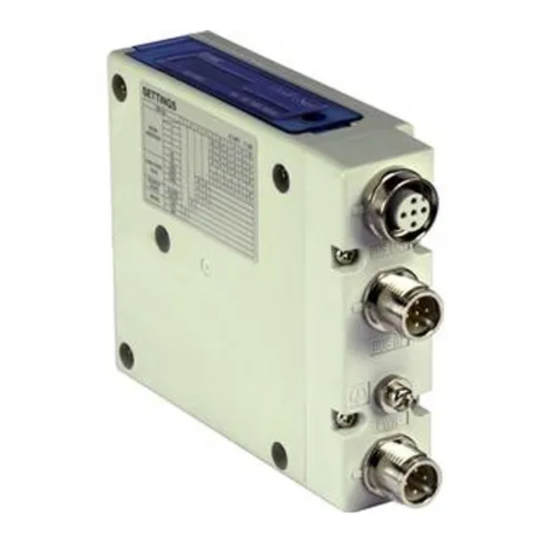
Fieldbus device - SI unit for PROFINET
IO-Link compatible
EX600-SPN3 / SPN4
The intended use of this product is to control pneumatic valves and I/O
while connected to the PROFINET (and IO-Link) protocols.
1 Safety Instructions
These safety instructions are intended to prevent hazardous situations
and/or equipment damage. These instructions indicate the level of
potential hazard with the labels of “Caution,” “Warning” or “Danger.”
They are all important notes for safety and must be followed in addition
to International Standards (ISO/IEC)
*1)
, and other safety regulations.
*1)
ISO 4414: Pneumatic fluid power - General rules relating to systems.
ISO 4413: Hydraulic fluid power - General rules relating to systems.
IEC 60204-1: Safety of machinery - Electrical equipment of machines.
(Part 1: General requirements)
ISO 10218-1: Manipulating industrial robots -Safety. etc.
•Refer to product catalogue, Operation Manual and
•Handling Precautions for SMC Products for additional information.
•Keep this manual in a safe place for future reference.
Caution
Caution indicates a hazard with a low level of risk which, if
not avoided, could result in minor or moderate injury.
Warning
Warning indicates a hazard with a medium level of risk
which, if not avoided, could result in death or serious injury.
Danger
Danger indicates a hazard with a high level of risk which, if
not avoided, will result in death or serious injury.
Warning
•Always ensure compliance with relevant safety laws and
standards.
•All work must be carried out in a safe manner by a qualified person in
compliance with applicable national regulations.
2 Specifications
The EX600 range of units can be connected to a fieldbus to realize the
reduction of input / output device wiring and a distributed control system.
The system communicates with the fieldbus through the SI unit.
One SI unit can be connected to manifold valves with up to 32 outputs,
and to input, output, I/O and IO-Link master units to a maximum of 9 units.
2.1 General specifications
Item Specifications
Ambient temperature
-
10 to +50
o
C
Ambient humidity
35 to 85%
RH (
n
o condensate
)
Ambient storage temperature
-
20 to +60
o
C
Withstand voltage
500 VAC applied for 1 minute
Insulation
resistance
500 VDC, 10 M
Ω
or more
Enclosure rating IP67 (manifold assembled)
Standard EMC / RoHS directive, UL (CSA)
Weight
300 g
2 Specifications (continued)
2.2 Electrical specifications
3 Name and function of Individual parts
No
Part Description
1 LED display Displays the SI unit status.
2 Display cover Display cover for switch setting.
3 Display cover screw To open the display cover.
4 Connector (PORT 2) Connector for Fieldbus Outputs.
5 Marker groove Groove for identification marker.
6 Valve plate hole Hole for valve plate mounting.
7 Valve plate groove Groove for valve plate mounting.
8 Joint bracket Bracket for joining to adjacent units.
9 Unit connector Connector for signal/power to next unit.
10 Connector (PORT 1) Connector for Fieldbus Inputs.
12 Seal cap (2 pcs.) For all unused M12 connectors
4 Assembly
4.1 Assembling the unit
Warning
Do not install the product unless the safety instructions have been read
and understood.
(1) Connect an I/O unit to the end plate. Digital and analogue units can
be connected in any order. Joint bracket screw tightening torque: 1.5
to 1.6 Nm.
(2) Add more
I/O units. Up to 9
I/O units can be connected
to one manifold.
(3)
Connect the SI unit. After
connecting the required I/O
units, connect the SI unit.
The connection method is
as above.
(4)
Mount the valve plate
(EX600-ZMV#) to the valve
manifold using the valve
screws (M3 x 8) supplied.
(Tightening torque: 0.6 to
0.7 Nm).
(5)
Connect the SI unit
assembly to the valve
manifold.
Insert the valve plate into
the valve plate mounting
groove.
Then fix using the valve plate mounting screws (M4 x 6) supplied
(Tightening torque: 0.7 to 0.8 Nm).
5 Installation
•Direct mounting
(1) When assembling six or more units, the middle part of the assembly
must be fitted with an intermediate reinforcing brace (EX600-ZMB1)
before mounting using 2-M4x5 screws (Tightening torque: 0.7 to 0.8
Nm).
(2) Mount and tighten the end plate at one end of the unit and mount the
intermediate reinforcing brace if required using M4 screws
(Tightening torque: 0.7 to 0.8 Nm).
Fix the end plate at the valve side while referring to the operation
manual for the applicable valve series.
5 Installation (continued)
•DIN rail mounting
(1) When assembling six or more units, the middle part of the complete
assembly must be fitted with an intermediate reinforcing brace for DIN
rail mounting (EX600-ZMB2), using 2-M4 x 6 screws.
(Tightening torque: 0.7 to 0.8 Nm).
(2) Mount the end plate bracket (EX600-ZMA2) to the end plate using 2-
M4 x 14 screws (Tightening torque: 0.7 to 0.8 Nm).
For the SY series, use end plate bracket (EX600-ZMA3).
(3) Hook the DIN rail mounting groove on to the DIN rail.
(4) Press the manifold using its side hooked to the DIN rail as a fulcrum
until the manifold is locked onto the DIL rail.
(5) Fix the manifold by tightening the DIN rail fixing screws (M4 x 20) on
the end plate bracket (Tightening torque: 0.7 to 0.8 Nm).
Refer to the Operation Manual for the applicable valve series on the
SMC website (URL: https://www.smcworld.com) for the mounting
method of the valve manifold.
5.1 Identification marker
The signal name of the input or output devices and unit address can
be written on the marker and can be installed on each unit.
Mount a marker (EX600-ZT1) into the marker groove as required.
•
5.2 Environment
Warning
•Do not use in an environment where corrosive gases, chemicals, salt
water or steam are present.
•Do not install in a location subject to vibration or impact in excess of
the product’s specifications.
•Do not mount in a location exposed to radiant heat that would result in
temperatures in excess of the product’s specifications.
Item Specifications
Power
supply
voltage /
current
Control and Input
power supply
24.0 VDC
2.0 A max.
Solenoid valve and
Output power supply
24.0 VDC
2.0 A max.
Internal current
consumption
120 mA maximum
Solenoid
valve
specification
Output
type
EX600-SPN3 PNP / source (negative
common)
EX600-SPN4 NPN / sink (positive common)
Number of outputs 32 outputs
Applicable valve series
24 VDC and 1.0 W max.
Solenoid valve with surge
voltage suppression
(manufactured by SMC)
Output condition during
communication error
HOLD / CLEAR / Force ON
Protection function Short circuit protection
2.3 Communication specifications
Item Specifications
Protocol PROFINET V2.35
Conformance class Class C (only for IRT switch function)
Communication speed 100 Mbps
Configuration file GSDML-V2.35-SMC-EX600-***.xml
Applicable functions
Fast Start Up
MRP (Media Redundancy Protocol)
System redundancy s.2
Web Server
ORIGINAL INSTRUCTIONS
EX600-SMY122EN
Page 2 of 2
6 Wiring
6.1 Wiring connections
•Communication Connection
Select the appropriate cables to mate with the connectors on the SI unit.
The PROFINET connection port pin layout is as shown below.
Connector Pin No. Signal name
PORT 1 / PORT 2
1 TX+
2 RX+
3 TX-
4 RX-
Warning
•Be sure to fit a seal cap (EX9-AWTS) on any unused connectors.
Proper use of the seal cap enables the enclosure to maintain IP67
specification.
7 Settings
7.1 Configuration
Download the latest GSDML file and refer to the operation manual on the
SMC website (URL: https://www.smcworld.com) for further information
on settings.
8 How to Order
Refer to the operation manual on the SMC website (URL:
https://www.smcworld.com) for How to order information.
9 Outline Dimensions (mm)
Refer to the operation manual on the SMC website (URL:
https://www.smcworld.com) for outline dimensions.
10 LED Display
Display
Content
ST(M)
Displays the diagnos
tic
status of the unit.
PWR Displays the status of the power supply voltage for
control and input.
PWR(V) Displays the status of the power supply voltage for
output.
SF
Displays the
system
status.
BF
Displays the
communication
status.
L/A
PORT1
Displays the communication status of
PORT 1
.
L/A
PORT2
Displays the communication status of
PORT 2
.
10 LED Display (continued)
LED
LED colour
Content
L/A
PORT 1
OFF
PORT 1
:
No Link, No Activity
Green ON
PORT 1
:
Link, No Activity
Green
flashing
PORT 1: Link,
Activity
L/A
PORT 2
OFF
PORT 2
:
No Link, No Activity
Green ON
PORT 2
:
Link, No Activity
Green
flashing
PORT 2: Link,
Activity
11 Maintenance
11.1 General Maintenance
Caution
•Not following proper maintenance procedures could cause the product
to malfunction and lead to equipment damage.
•If handled improperly, compressed air can be dangerous.
•Maintenance of pneumatic systems should be performed only by
qualified personnel.
•Before performing maintenance, turn off the power supply and be sure
to cut off the supply pressure. Confirm that the air is released to
atmosphere.
•After installation and maintenance, apply operating pressure and
power to the equipment and perform appropriate functional and
leakage tests to make sure the equipment is installed correctly.
•If any electrical connections are disturbed during maintenance, ensure
they are reconnected correctly and safety checks are carried out as
required to ensure continued compliance with applicable national
regulations.
•Do not make any modification to the product.
•Do not disassemble the product, unless required by installation or
maintenance instructions
•Stop operation if the product does not function correctly.
12 Limitations of Use
12.1 Limited warranty and Disclaimer/Compliance Requirements
Refer to Handling Precautions for SMC Products.
13 Product disposal
This product should not be disposed of as municipal waste. Check your
local regulations and guidelines to dispose of this product correctly, in
order to reduce the impact on human health and the environment.
14 Contacts
Refer to www.smcworld.com or www.smc.eu for your local distributor /
importer.
URL : https://www.smcworld.com (Global) https://www.smc.eu (Europe)
SMC Corporation, Akihabara UDX15F, 4-14-1, Sotokanda, Chiyoda-ku, Tokyo 1 1
21
Specifications are subject to change without prior notice from the manufacturer.
© 2021 SMC Corporation All Rights Reserved.
Template DKP50047-F-085L
L/A PORT1
LED
LED
c
olour
Operation
ST(M)
OFF
The power supply for control and input
is OFF.
Green ON
Normal operation.
Green
flashing
Diagnostic error in I/O unit detected.
Red
flashing
Either of the following diagnostics errors
detected (with diagnostics enabled):
•Valve ON/OFF counter exceeded the set
value.
•
V
alve is short circuited or disconnected.
Red/Green
flashing
Communication error detected between SI unit
and I/O unit.
Red ON
SI unit has failed.
PWR
Green ON The power supply voltage for control and input
is
normal.
Red ON The power supply voltage for control and input
is
below 19 VDC
(
with
diagnostic
s
enabled)
.
PWR(V)
OFF The power supply voltage for output is OFF or
below 19 VDC
(
with
diagnostic
s
disabled)
.
Green ON
The
power supply
voltage
for
output
is
normal.
Red ON The power supply voltage for output is OFF or
Below 19 VDC
(with diagnostics enabled)
.
SF
OFF
Normal operation.
Red
ON
Diagnostics error detected.
Green
flashing
Node flashing test
BF
OFF
PROFINET communication established.
Red
flashing
The PLC configuration data and the EX600
configura
t
ion
are
not consistent
.
Red ON
Either of the following conditions:
•Device name setting to PLC and SI unit is
not consistent.
•Communication cable not connected.
•
PLC or SI unit
is faulty
.
L/A PORT2
ST(M) PWR PWR(V) SF BF

This manual suits for next models

1

Other SMC Networks Control Unit manuals

SMC Networks VTA301 Series User manual

SMC Networks

SMC Networks VTA301 Series User manual

SMC Networks DXT1215 User manual

SMC Networks

SMC Networks DXT1215 User manual

SMC Networks JSY1000-E Series User manual

SMC Networks

SMC Networks JSY1000-E Series User manual

SMC Networks VKF300 Series Manual

SMC Networks

SMC Networks VKF300 Series Manual

SMC Networks 4501 Series User manual

SMC Networks

SMC Networks 4501 Series User manual

SMC Networks XT323-4 Manual

SMC Networks

SMC Networks XT323-4 Manual

SMC Networks XGT312-50336 Series User manual

SMC Networks

SMC Networks XGT312-50336 Series User manual

SMC Networks VJ3000 Manual

SMC Networks

SMC Networks VJ3000 Manual

SMC Networks AKP Series User manual

SMC Networks

SMC Networks AKP Series User manual

SMC Networks VF1000 Series Manual

SMC Networks

SMC Networks VF1000 Series Manual

SMC Networks EX260-SPL1 User manual

SMC Networks

SMC Networks EX260-SPL1 User manual

SMC Networks VOA325 Series User manual

SMC Networks

SMC Networks VOA325 Series User manual

SMC Networks EX260 Series User manual

SMC Networks

SMC Networks EX260 Series User manual

SMC Networks SX10 Series User manual

SMC Networks

SMC Networks SX10 Series User manual

SMC Networks XLD Series User manual

SMC Networks

SMC Networks XLD Series User manual

SMC Networks VV100 Series Manual

SMC Networks

SMC Networks VV100 Series Manual

SMC Networks EXW1-RDX# Series User manual

SMC Networks

SMC Networks EXW1-RDX# Series User manual

SMC Networks HRS-DI006 User manual

SMC Networks

SMC Networks HRS-DI006 User manual

SMC Networks JSXH31-CP X2 Series User manual

SMC Networks

SMC Networks JSXH31-CP X2 Series User manual

SMC Networks JSXF Series User manual

SMC Networks

SMC Networks JSXF Series User manual

SMC Networks EX245-FPS1 User manual

SMC Networks

SMC Networks EX245-FPS1 User manual

SMC Networks VXS23 Manual

SMC Networks

SMC Networks VXS23 Manual

SMC Networks VHK-A User manual

SMC Networks

SMC Networks VHK-A User manual

SMC Networks VHS20 Series User manual

SMC Networks

SMC Networks VHS20 Series User manual

Popular Control Unit manuals by other brands

Terra UC380 user manual

Terra

Terra UC380 user manual

Lenze E94AZHY0025 Mounting instructions

Lenze

Lenze E94AZHY0025 Mounting instructions

Definox DPX1EBC Maintenance notice

Definox

Definox DPX1EBC Maintenance notice

LSI MegaRAID LSIiBBU01 Quick installation guide

LSI

LSI MegaRAID LSIiBBU01 Quick installation guide

Compac OPT SCR200 installation manual

Compac

Compac OPT SCR200 installation manual

Arduino HM-11 user manual

Arduino

Arduino HM-11 user manual

schmersal SRB 304ST operating instructions

schmersal

schmersal SRB 304ST operating instructions

DAZE Dynamic Power Manager installation manual

DAZE

DAZE Dynamic Power Manager installation manual

Zamel EXTA EDM-01 instruction manual

Zamel

Zamel EXTA EDM-01 instruction manual

SpeedTurtle Easy Flash Module 3.0 user manual

SpeedTurtle

SpeedTurtle Easy Flash Module 3.0 user manual

entegris NT 6300 user guide

entegris

entegris NT 6300 user guide

Franklin Wireless S600 manual

Franklin Wireless

Franklin Wireless S600 manual

Baldwin Boxall BT10 operating instructions

Baldwin Boxall

Baldwin Boxall BT10 operating instructions

Emerson ALCO Thermo TX6 installation instructions

Emerson

Emerson ALCO Thermo TX6 installation instructions

Marvell Avastar SP88W8782-MA0 user guide

Marvell

Marvell Avastar SP88W8782-MA0 user guide

DOLD SAFEMASTER PRO UG 6951 user manual

DOLD

DOLD SAFEMASTER PRO UG 6951 user manual

Dataton SMARTPAX QC Product Sheets

Dataton

Dataton SMARTPAX QC Product Sheets

Valmet Flowrox PVEG Installation, operation and maintenance instructions

Valmet

Valmet Flowrox PVEG Installation, operation and maintenance instructions

manuals.online logo
manuals.online logoBrands
  • About & Mission
  • Contact us
  • Privacy Policy
  • Terms and Conditions

Copyright 2025 Manuals.Online. All Rights Reserved.