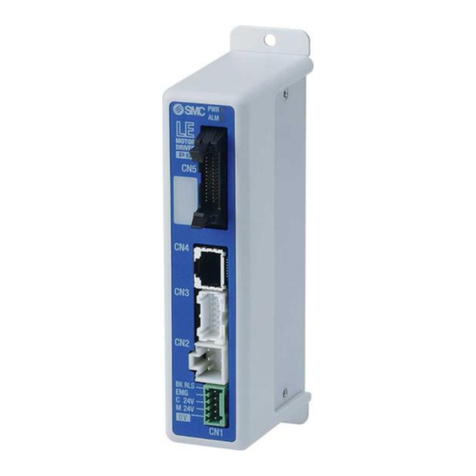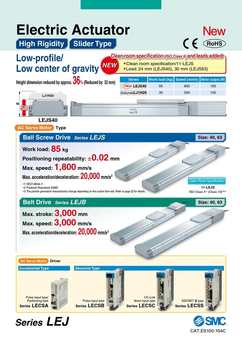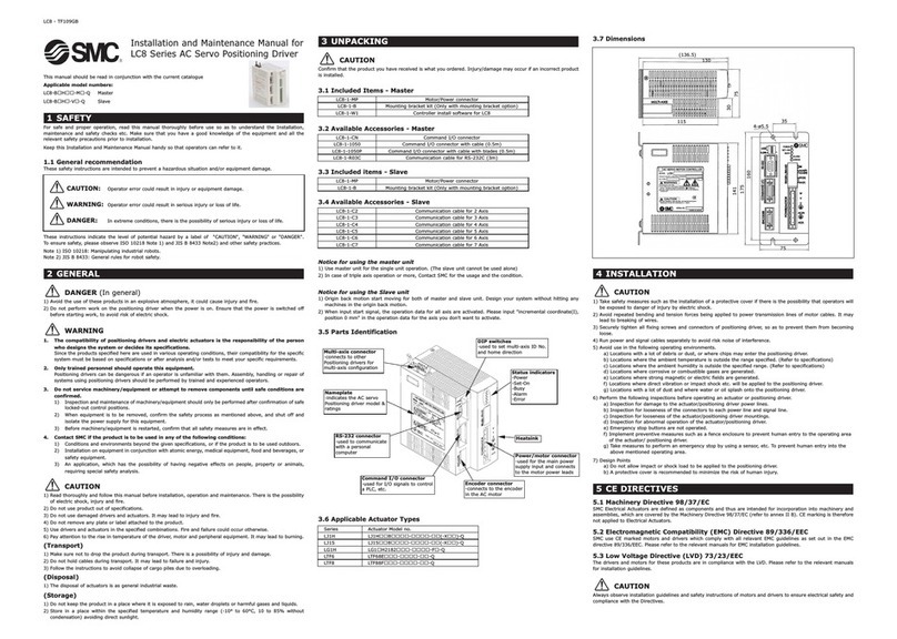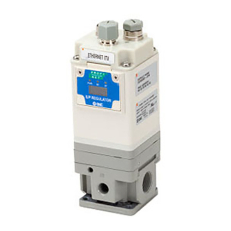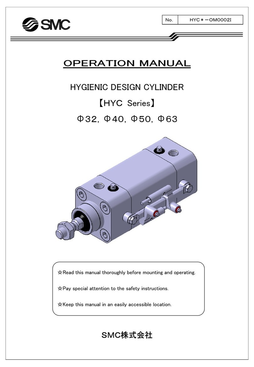
Specifications
Basic Specifications
Note 4) Applicable to non-magnetizing lock.
Decimal display
Hexadecimal display
10
A
11
b
12
c
13
d
14
E
15
F
Note 1) Do not use the power supply of “inrush current prevention type” for the controller input power supply. When conformity to UL is required, the
electric actuator and controller should be used with a UL1310 Class 2 power supply.
Note 2) The power consumption changes depending on the actuator model. Refer to the each actuator’s operation manual etc. for details.
Note 3) “10” to “15” in decimal number are displayed as follows in the 7-segment LED.
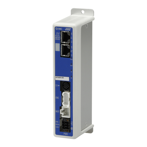
Item LECP1
Compatible motor Step motor (Servo/24 VDC)
Power supply Note 1) Power supply voltage: 24 VDC ±10 % Note 2)
[Including the motor drive power, control power supply, stop, lock release]
Parallel input 6 inputs (Photo-coupler isolation)
Parallel output 6 outputs (Photo-coupler isolation)
Stop points 14 points (Position number 1 to 14(E))
Compatible encoder Incremental A/B phase (800 pulse/rotation)
Memory EEPROM
LED indicator LED (Green/Red) one of each
7-segment LED display Note 3)
1 digit, 7-segment display (Red) Figures are expressed in hexadecimal (“10” to “15” in decimal number are expressed as “A” to “F”)
Lock control Forced-lock release terminal Note 4)
Cable length [m] I/O cable: 5 or less, Actuator cable: 20 or less
Cooling system Natural air cooling
Operating temperature range [
°
C]
0 to 40 (No freezing)
Operating humidity range [%RH]
90 or less (No condensation)
Storage temperature range [
°
C]
−10 to 60 (No freezing)
Storage humidity range [%RH]
90 or less (No condensation)
Insulation resistance [MΩ]
Between the housing and SG terminal: 50 (500 VDC)
Weight [g] 130 (Screw mounting), 150 (DIN rail mounting)
LECP1 Series
How to Order
C 1LE P
1N
1
1
P
Controller
Compatible motor
Controller type
Number of step data (Points)
Parallel I/O type
I/O cable length [m]
I/O cable length [m]
Actuator part number
Actuator type
(Except cable specifications and actuator options)
Example: Enter “LEFS16A-400” for the
LEFS16A-400B-R11N1.
∗When controller equipped type is selected
when ordering the LE series, you do not
need to order this controller.
Option
Note) DIN rail is not included.
Order it separately.
Refer to “How to Order” in the actuator catalogue and indicate the model.
For compatible actuators, refer to the table below.
Example: LEFS16B-100-R31N1
—Screw mounting
DNote) DIN rail mounting
—Without cable
11.5
33
55
—Without cable
11.5
33
55
NNPN
PPNP
114 (Programless)
PStep motor (Servo/24 VDC)
—Without controller
1N With programless controller (NPN)
1P With programless controller (PNP)
LEFS16A-400
LEFS16B-100-R3
[CE-compliant products]
EMC compliance was tested by combining the electric actuator LE series and the controller LEC series.
The EMC depends on the configuration of the customer’s control panel and the relationship with other electrical
equipment and wiring. Therefore, conformity to the EMC directive cannot be certified for SMC components
incorporated into the customer’s equipment under actual operating conditions. As a result, it is necessary for the
customer to verify conformity to the EMC directive for the machinery and equipment as a whole.
[UL-compliant products]
When conformity to UL is required, the electric actuator and controller should be used with a UL1310 Class 2 power supply.
Caution The controller is sold as
single unit after the
compatible actuator is set.
Confirm that the combination of the
controller and the actuator is correct.
Part number for actuator and controller set.
∗Refer to the operation manual for using
the products. Please download it via our
website, http://www.smc.eu
Compatible actuators
LEF LEL LEY LES LEPLER LEH
Controller
Controller with actuator
LEM
1
