manuals.online logo
Brands
  1. Home
  2. •
  3. Brands
  4. •
  5. SMC Networks
  6. •
  7. Controllers
  8. •
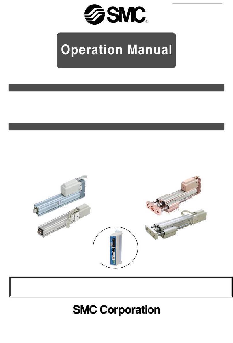
  9. SMC Networks MY3 Series User manual

SMC Networks MY3 Series User manual

CAT.ES20-165 B
Mechanically Jointed
Rodless Cylinders
Rubber
bumper
Air
cushion
Stroke
adjusting
unit
Side
support
25 40 63
Bore size (mm)
16
Made to
Order
Note) Except the MY3A
Long stroke
(-XB11)
Helical insert
threads (-X168)
Holder mounting
bracket Note)
(-X416, X417)
Copper-free
(20-)
Floating
bracket
MY3A
MY3B
Series Type Piping
type
Basic standard
type
MY3M Slide bearing
type
Basic short
type
Centralized
piping
Standard
piping
Series VariationsSeries VariationsSeries Variations
Series MY3B
Series MY3M
Series MY3A
Basic standard type (Air cushion)
Series MY3B
Slide bearing type (Air cushion)
Series MY3M
Basic short type (Rubber bumper)
Series MY3A
MY3A3B.qxd 06.2.17 9:13 AM Page 1
Series
MY3A
ø16
110
ø25
150
ø40
240
ø63
320
MY3B
MY3M 122 178 276 356
MY1B
MY1M 160 220 340 460
(mm)
Series
MY3A
MY3B
ø16 ø25 ø40 ø63
MY1B
27 37 54 84
37 54 84 116
MY1M 40 54 84 130
MY3M 33 45 63 93
(mm)
MY1B/MY1M (with air cushion)
MY3A (with rubber bumper)
MY1M
High functionality with reduced height and length
Overall length (Z) reduced by
140
mm at the maximum
Overall Length (Z) Weight
Height (H) reduced by
36
% at the maximum
Weight reduced by
53
% at the maximum
Series
MY3A
MY3B
MY1B
MY1M
MY3M
ø16
0.34
0.35
0.73
ø25
0.99
1.09
1.57
ø40
2.95
3.08
4.41
ø63
8.26
8.99
14.5
0.45
0.91
1.32
2.12
3.65
7.00
9.99
18.9
(kg)
Height (H)
Overall length (Z + Stroke)
∗ At 100 mm stroke
MY3B
MY3BMY3B
MY3B
Basic standard type
(Air cushion)
Mechanically Jointed Rodless Cylinders
Series MY3
MY3A
MY3A
MY3A
Basic short type
(Rubber bumper)
MY3B/MY3M (with air cushion)
Loading Capacity
200
180
160
140
MY3M
MY3A
MY3B
MY3M
MY3A
MY3B
120
100
80
60
40
20
0
70
60
50
40
30
20
10
0
16 25 40 63 16 25
Bore size (mm) Bore size (mm)
Allowable moment (Nm)
Load weight (kg)
40 63
NEW
NEW
Work pieces can be loaded
directly on the work table
due to the integrated guide.
M2
m1
MY1B MY3A/3BMY3A/3B MY3MMY3M
Height (H)
Height (H)
SMC
SMC
SMC
MY3M
MY3MMY3M
MY3M
Slide bearing type
(Air cushion)
Features 1
MY3A3B.qxd 06.2.17 9:13 AM Page 2
Auto Switch
Stroke Adjusting Unit
Side Support
The cylinder tube can be fixed from the upper or lower side.
(Page 15, 27)
Centralized Piping
Can be mounted on both sides
from the front direction.
(MY3B/3M)
(MY3A/3B)
Floating Bracket
Easy connection with external guide. Vertical and lateral mounting is possible. (Page 16)
Integrated piping in the
head cover is possible.
(Refer to the back of
page 6.)
Side support
Auto switch
Positioning cushion mechanism
Air cushion
(MY3B/3M)
Passage for
centralized piping
The uniquely designed piston
shape enables reduction of
the height and length as well
as practical arrangement of
the common piping passages,
cushion mechanism and posi-
tioning mechanism. This has
achieved drastic miniaturiza-
tion and weight reduction.
Features 2
MY3A3B.qxd 06.2.17 9:13 AM Page 3
Guideline for Tentative Model Selection
Series Type Note
Basic short type
Basic standard type
Slide bearing type
MY3A
MY3B
MY3M
Stroke accuracy
Guideline for tentative model selection
Use of external guide
Direct loaded Table accuracy
Generally combined with a separare
guide making it, by length, more compact.
Generally combined with a separare
guide, when stroke accuracy is required.
Mounting a work piece directly on the
product, when stroke accuracy is required.
Selection Flow Chart
When an external guide is used, the selection confirmation of the guide capacity should follow the selection procedure
of the external guide.
The MY3 series allow direct load application within the allowable range for the built-in guide. The payload in this case
will vary depending on the driving speed and the mounting orientation of the cylinder. Please refer to the flow below and
confirm the selection. (For more detailed description of the selection flow, please refer to the instruction manual.)
∗ When using an external cushioning unit, we recommend installing a suitable unit near the load’s
center of gravity.
It is possible to select all models of mechanically jointed rodless cylinder (the MY3 series) according
to the procedure indicated above.
Refer to the separate instruction manual for further explanation, and please consult with SMC
regarding any questions.
Tentative selection of cylinder model
MY3A:Basic short type
MY3B:Basic standard type
MY3M:Slide bearing type
Operating conditions
m:
Load weight
(kg)
V:
Speed
(mm/s)
P:
Operating pressure
(MPa)
Mounting
direction:
Examine the cushioning
mechanism at stroke end.
Built-in cushion
stroke adjusting
unit
External
shock
absorber
Examine the auto switch
mounting (model).
Model
selected
OK OK
OK
OK
Re-examine the operating conditions.
Select larger
cylinder size.
Change the
guide type.
NG NG
NG NG
In case of the MY3A
and MY3B only
Series MY3
Model Selection 1
The following are steps for selecting the MY3 series which is best suited to your application.
Determination
of load weight
and allowable
moment
Select the
different guide type.
∗Please refer to the informa-
tion by the guide
manufacturer.
Most suitable Suitable Usable Not recommended
Note) The table accuracy means the amount of table deflection when a moment is applied.
Front matter 1
MY3A3B.qxd 06.2.17 9:13 AM Page 4
Maximum operating speed
Front matter 2
Model Selection
Series MY3
Note 1) The shock absorber must meet the conditions mentioned on page 7.
Note 2) As the external shock absorber, a unit with appropriate capacity and features should be installed close to the load center of gravity.
Note 3) Use the stroke adjusting unit of the MY3B series with an external guide.
Note 4) Shown below are the details of the maximum operating speed for the stroke adjusting unit.
How to mount
a load
Direct loaded
Use of external
guide
Rubber bumper
Air cushion
Shock absorber
External shock
absorber Note 1)
Rubber bumper
Air cushion
Shock absorber
External shock
absorber Note 1)
Stroke positioning Shock absorber
1000 1500
(mm/s)
500
MY3A
MY3B
MY3M
MY3A MY3B
Cylinder stroke end
Stroke adjusting unit
(Option: L, H unit)
External stopper
Cylinder stroke end
Stroke adjusting unit
(Option: L, H unit)
External stopper
MY3M
MY3M
MY3A
MY3B
MY3B
MY3A MY3B
Note 2)
Note 4)
Note 2)
Note 2)
Note 3)
Note 4)
Outside the fine stroke adjustment range means that when a holder mounting bracket (X416, X417) is used.
Holder mounting bracket →Refer to page 34, 35.
MY3 Series, Maximum Operating Speed when Using the Stroke Adjusting Unit Unit: mm/s
Series
MY3B
MY3M
Bore size (mm)
16
25, 40, 63
16, 25, 40, 63
Stroke adjustment range
L unit
H unit
L, H unit
L, H unit
Inside the fine stroke adjustment range
800
1000
1000
1500
Outside the fine stroke adjustment range
500
800
800
800
MY3A3B.qxd 06.2.17 9:13 AM Page 5
Front matter 3
Series MY3
Types of Moment Applied to Rodless Cylinders
Multiple moments may be generated depending on the mounting orientation, load and position of the center of gravity.
Calculation of Guide Load Factor
1.
Maximum load weight (1), static moment (2), and dynamic moment (3) (at the time of impact with stopper) must be examined for the selection calculations.
∗To evaluate, use υa (average speed) for (1) and (2), and υ(impact speed υ= 1.4υa) for (3). Calculate m max for (2) from the maximum allowable load graph (m1, m2, m3 )
and Mmax for (2) and (3) from the maximum allowable moment graph (M1, M2, M3).
2. Reference formulas [Dynamic moment at impact]
Use the following formulas to calculate dynamic moment when taking stopper impact into consideration.
m:Load weight (kg)
F:Load (N)
FE:
Load equivalent to impact (at impact with stopper) (N)
υa: Average speed (mm/s)
M:Static moment (N •m)
υ= 1.4υa (mm/s) FE= 1.4υa x δx m •g
1
ME=
—
•FE•L1= 4.57υaδm L1 (N •m)
3
Note 4) 1.4υaδ is a dimension less coefficient for calculating impact force.
Note 5) Average load coefficient = :
This coefficient is for averaging the maximum load moment at the time of stopper impact according to service life calculations.
3. For detailed selection procedure, please refer to pages 2, 3, 18, 19.
Coordinates and Moments
z
y
M3: Yawing
xM2: Rolling
M1: Pitching
Horizontal
mounting
Wall
mounting
Ceiling
mounting
m3x g
x
M2
z
M3
X
Z
y
m1x g
M1
X
x
M2
Yy
m2x g
M1
X
x
M2
Y
Vertical
mounting
g: Gravitational acceleration
M1
Z
M3
zy
Y
Note)
m
4
is a mass movable by thrust. Use 0.3 to 0.7 times the thrust
(differs depending on the operating speed) as a guide for actual use.
Mounting direction
Static load m
Horizontal
m1
Ceiling
m2
Wall
m3
M1
M2
M3
m1x gx X
m1x gx Y
—
m2x gx X
m2x gx Y
—
—
m3x gx Z
m3x gx X
m4x gx Z
—
m4x gx Y
Vertical
m4
M1
FE
M3
Y
υa
Mounting direction
Dynamic load
FE
Horizontal Ceiling Wall Vertical
Note) Regardless of the mounting orientation, dynamic moment is
calculated with the formulae above.
Dynamic moment M2E will not be generated.
1.4υax δx mnx g
x FEx Z
1
3
x FEx Y
1
3
M1E
M2E
M3E
Load Weight and Static Moment
g: Gravitational acceleration
υa: Average speed
δ: Bumper coefficient
Note 1) Moment caused by the load, etc., with cylinder in resting condition.
Note 2) Moment caused by the impact load equivalent at the stroke end (at the time of impact with stopper).
Note 3) Depending on the shape of the work piece, multiple moments may occur. When this happens, the sum of the load factors (Σα) is the total of all such moments.
FE
ME
m
L
1
υ
Z
FE
M1E
υa
M3E
Dynamic Moment
mnx g
mnx g
m4x g
Static
moment
Dynamic
moment
Note)
Σα=+ + <1
=
Load weight
[
m
]
Maximum load weight
[
m max
]
Static moment
[
M
]
Allowable static moment
[
Mmax
]
Sum of guide
load factors
Note 1) Dynamic moment [M
E
]
Allowable dynamic moment
[
M
E
max
]
Note 2)
Note 5)
Note 4)
1
3
•
••
υ: Impact speed (mm/s)
L1: Distance to the load’s center of gravity (m)
ME: Dynamic moment (N •m)
δ: Bumper coefficient
With rubber bumper = 4/100
With air cushion = 1/100
With shock absorber = 1/100
g:Gravitational acceleration (9.8 m/s2)
()
MY3A3B.qxd 06.2.17 9:13 AM Page 6
W: Work piece (0.8 kg)
MY3A25-500
xy
z
xz
y
x
zy
xy
z
Mounting Direction
1. Horizontal
mounting
2. Wall
mounting
3. Ceiling
mounting 4. Vertical
mounting
X
m1
m1
M1
20
10
Z
Y
Y
X
5
W
Work piece
no.
0.8 kg
Weight
(m)
5 mm
X-axis
10 mm
Y-axis
Center of gravity
Z-axis
20 mm
Work Piece Weight and Center of Gravity
m1
M2
Y
Calculation of Guide Load Factor
Front matter 4
Series MY3
Model Selection 2
The following are steps for selecting the MY3 series which is best suited to your application.
Cylinder •••••••••••••••••••••••••••••••••••••• MY3A25-500
Average operating speed υa •••••••••• 300 mm/s
Mounting direction ••••••••••••••••••••••• Horizontal mounting
Cushion •••••••••••••••••••••••••••••••••••••• Rubber bumper (δ= 4/100)
1 Operating Conditions
2 Load Blocking
m1: Mass
m1max (from qof graph MY3A ⁄ m1) = 10.7 (kg) •••••••••••••••••••••••••••••••••••••••••
Load factor α1= m1⁄ m1max = 0.8 ⁄ 10.7 = 0.08
M1: Moment
M1max (from wof graph MY3A ⁄ M1) = 4 (Nm) ••••••••••••••••••••••••••••••••••••••••••••••••••••••••••••••••••
M1= m1x g x X = 0.8 x 9.8 x 5 x 10-3= 0.04 (Nm)
Load factor α2= M1⁄ M1max = 0.04 ⁄ 4 = 0.01
M2: Moment
M2 max (from eof graph MY3A ⁄ M2) = 0.8 (Nm) ••••••••••••••••••••••••••••••••••••••••••••••••••••••••••••••
M3= m1x g x Y = 0.8 x 9.8 x 10 x 10-3= 0.08 (Nm)
Load factor α3= M2⁄ M2 max = 0.08 ⁄ 0.8 = 0.1
3 Calculation of Load Factor for Static Load
MY3A3B.qxd 06.2.17 9:13 AM Page 7
Front matter 5
Series MY3
Load Weight Allowable Moment
M1
M3
Y
FE
FE
Z
M1E
M3E
Calculation of Guide Load Factor
Moment (Nm)
Moment (Nm)
Moment (Nm)
MY3A, MY3B/M1
MY3A, MY3B/m1MY3A, MY3B/M2MY3A, MY3B/M3
Piston speed (mm/s) Piston speed (mm/s) Piston speed (mm/s)Piston speed (mm/s)
MY3A / 3B16
MY3A / 3B25
MY3A / 3B40
MY3A / 3B63
MY3A / 3B16
MY3A / 3B25
MY3A / 3B40
MY3A / 3B63
MY3A / 3B16
MY3A / 3B25
MY3A / 3B40
MY3A / 3B63
200
100
50
40
30
20
0.5
1
10
5
4
3
2
15001000500400300200100
0.05
50
40
30
20
0.1
1
0.5
0.4
0.3
0.2
10
5
4
3
2
15001000500400300200100
50
100
40
30
20
0.1
1
0.5
0.4
0.3
0.2
10
5
4
3
2
15001000500400300200100
Load weight (kg)
MY3A / 3B16
MY3A / 3B25
MY3A / 3B40
MY3A / 3B63
0.05
30
20
0.1
1
0.5
0.4
0.3
0.2
10
5
4
3
2
15001000500400300200100
∗ Refer to page 18 for the MY3M.
Equivalent load FEat impact
FE= 1.4υa x δx mx g= 1.4 x 300 x x 0.8 x 9.8 = 131.7 (N)
M1E: Moment
M1E max (from rof graph MY3A ⁄ M1where 1.4υa = 420 mm/s) = 2.85 (Nm) ••••••••••••••
M1E = x FEx Z = x 131.7 x 20 x 10-3= 0.88 (Nm)
Load factor α4= M1E ⁄ M1E max = 0.88 ⁄ 2.85 = 0.31
M3E: Moment
M3E max (from tof graph MY3A ⁄ M3where 1.4υa = 420 mm/s) = 0.95 (Nm) ••••••••••••••••••••
M3E = x FEx Y = x 131.7 x 10 x 10-3= 0.44 (Nm)
Load factor α5= M3E ⁄ M3E max = 0.44 ⁄ 0.95 = 0.43
4
——
100
1
——
3
1
——
3
1
——
3
1
——
3
4 Calculation of Load Factor for Dynamic Moment
The above calculation is within the allowable value, and therefore the selected model can be used.
Select a shock absorber separately.
In an actual calculation, when the sum of guide load factors Σα in the formula above is more than 1, consider
decreasing the speed, increasing the bore size, or changing the product series.
5 Sum and Examination of Guide Load Factors
MY3A3B.qxd 06.2.17 9:13 AM Page 8
Basic short type (Rubber bumper)
ø16, ø25, ø40, ø63
Basic standard type (Air cushion)
ø16, ø25, ø40, ø63
1
Series MY3A
Series MY3B
MY3A3B.qxd 06.2.17 9:13 AM Page 9
W: Work piece (0.8 kg)
MY3A25-500
xy
z
xz
y
x
zy
xy
z
X
m1
m1
M1
20
10
Z
Y
Y
X
5
m1
M2
Y
Calculation of Guide Load Factor
Series MY3A/3B
Model Selection
The following are steps for selecting the MY3 series which is best suited to your application.
2
Mounting Direction
1. Horizontal
mounting
2. Wall
mounting
3. Ceiling
mounting 4. Vertical
mounting
Cylinder •••••••••••••••••••••••••••••••••••••• MY3A25-500
Average operating speed υa •••••••••• 300 mm/s
Mounting direction ••••••••••••••••••••••• Horizontal mounting
Cushion •••••••••••••••••••••••••••••••••••••• Rubber bumper (δ= 4/100)
1 Operating Conditions
2 Load Blocking
m1: Mass
m1max (from qof graph MY3A ⁄ m1) = 10.7 (kg) •••••••••••••••••••••••••••••••••••••••••
Load factor α1= m1⁄ m1max = 0.8 ⁄ 10.7 = 0.08
M1: Moment
M1max (from wof graph MY3A ⁄ M1) = 4 (Nm) ••••••••••••••••••••••••••••••••••••••••••••••••••••••••••••••••••
M1= m1x g x X = 0.8 x 9.8 × 5 x 10-3= 0.04 (Nm)
Load factor α2= M1⁄ M1max = 0.04 ⁄ 4 = 0.01
M2: Moment
M2 max (from eof graph MY3A ⁄ M2) = 0.8 (Nm) ••••••••••••••••••••••••••••••••••••••••••••••••••••••••••••••
M3= m1x g x Y = 0.8 x 9.8 x 10 x 10-3= 0.08 (Nm)
Load factor α3= M2⁄ M2 max = 0.08 ⁄ 0.8 = 0.1
3 Calculation of Load Factor for Static Load
W
Work piece
no.
0.8 kg
Mass
(m)
5 mm
X-axis
10 mm
Y-axis
Center of gravity
Z-axis
20 mm
Work Piece Weight and Center of Gravity
MY3A3B.qxd 06.2.17 9:13 AM Page 10
Load Weight Allowable Moment
M1
M3
Y
FE
FE
Z
M1E
M3E
Calculation of Guide Load Factor
Moment (Nm)
Moment (Nm)
Moment (Nm)
MY3A, MY3B/M1
MY3A, MY3B/m1MY3A, MY3B/M2MY3A, MY3B/M3
Piston speed (mm/s) Piston speed (mm/s) Piston speed (mm/s)Piston speed (mm/s)
200
100
50
40
30
20
0.5
1
10
5
4
3
2
15001000500400300200100
0.05
50
40
30
20
0.1
1
0.5
0.4
0.3
0.2
10
5
4
3
2
15001000500400300200100
50
100
40
30
20
0.1
1
0.5
0.4
0.3
0.2
10
5
4
3
2
15001000500400300200100
Load weight (kg)
0.05
30
20
0.1
1
0.5
0.4
0.3
0.2
10
5
4
3
2
15001000500400300200100
∗ Refer to page 18 for the MY3M.
3
Model Selection
Series MY3A/3B
ø63
ø40
ø25
ø16
ø63
ø40
ø25
ø16
ø63
ø40
ø25
ø16
ø63
ø40
ø25
ø16
4 Calculation of Load Factor for Dynamic Moment
The above calculation is within the allowable value, and therefore the selected model can be used.
Select a shock absorber separately.
In an actual calculation, when the sum of guide load factors Σα in the formula above is more than 1, consider
decreasing the speed, increasing the bore size, or changing the product series.
5 Sum and Examination of Guide Load Factors
Equivalent load FEat impact
FE= 1.4υa x δx mx g= 1.4 x 300 x x 0.8 x 9.8 = 131.7 (N)
M1E: Moment
M1E max (from rof graph MY3A ⁄ M1where 1.4υa = 420 mm/s) = 2.85 (Nm) ••••••••••••••
M1E = x FEx Z = x 131.7 x 20 x 10-3= 0.88 (Nm)
Load factor α4= M1E ⁄ M1E max = 0.88 ⁄ 2.85 = 0.31
M3E: Moment
M3E max (from tof graph MY3A ⁄ M3where 1.4υa = 420 mm/s) = 0.95 (Nm) ••••••••••••••••••••
M3E = x FEx Y = x 131.7 x 10 x 10-3= 0.44 (Nm)
Load factor α5= M3E ⁄ M3E max = 0.44 ⁄ 0.95 = 0.43
4
——
100
1
——
3
1
——
3
1
——
3
1
——
3
MY3A3B.qxd 06.2.17 9:13 AM Page 11
Maximum Allowable Moment / Maximum Allowable Load
4
Series MY3A/3B
Series
MY3A
MY3B
Bore size
(mm)
16
25
40
63
Maximum allowable moment (Nm)
M1M2M3
Maximum allowable load (kg)
m1m2m3
1.8
6
24
70
0.7
2
10
30
1.5
4
10
20
6
16
40
80
3
6
12
24
0.3
1.2
4.8
19
The above values are the maximum allowable values for moment and load. Refer to each graph regarding the maximum
allowable moment and maximum allowable load for a particular piston speed.
MY3A, MY3B/M1
MY3A, MY3B/m1MY3A, MY3B/m2MY3A, MY3B/m3
MY3A, MY3B/M2MY3A, MY3B/M3
Maximum Allowable Moment
Select the moment from within the range of operating limits shown in the graphs. Note that the maximum allowable load value may sometimes
be exceeded even within the operating limits shown in the graphs. Therefore, also check the allowable load for the selected conditions.
Maximum Allowable Load
Select the load from within the range of limits shown in the graphs. Note that the maximum allowable moment value may sometimes be
exceeded even within the operating limits shown in the graphs. Therefore, also check the allowable moment for the selected conditions.
Piston speed (mm/s)
MY3A max. MY3B max.
Moment (Nm)
ø16
ø25
ø40
ø63
0.05
50
40
30
20
0.1
1
0.5
0.4
0.3
0.2
10
5
4
3
2
15001000500400300200100
Piston speed (mm/s)
MY3A max. MY3B max.
Moment (Nm)
ø16
ø25
ø40
ø63
100
50
40
30
20
0.1
1
0.5
0.4
0.3
0.2
10
5
4
3
2
15001000500400300200100
Piston speed (mm/s)
MY3B max.
MY3A max.
Load weight (kg)
ø16
ø25
ø40
ø63
200
100
50
40
30
20
0.5
1
10
5
4
3
2
15001000500400300200100
Piston speed (mm/s)
MY3A max. MY3B max.
Moment (Nm)
ø16
ø25
ø40
ø63
0.05
30
20
0.1
1
0.5
0.4
0.3
0.2
10
5
4
3
2
15001000500400300200100
Piston speed (mm/s)
MY3B max.
MY3A max.
Load weight (kg)
ø16
ø25
ø40
ø63
15001000500400300200100
50
40
30
20
0.1
1
0.5
0.4
0.3
0.2
10
5
4
3
2
Piston speed (mm/s)
ø63
ø16
MY3B max.
MY3A max.
Load weight (kg)
ø40
100
50
40
30
20
0.5
1
10
5
4
3
2
15001000500400300200100
ø25
MY3A3B.qxd 06.2.17 9:13 AM Page 12
Absorption Capacity of Rubber Bumper (MY3A)
Rubber Bumper Displacement (Additional Stroke due to Pressure on Each Side)
The stop position of the built-in rubber bumper of the MY3A series varies depending on the operating pressure. For alignement at
the stroke end, find the guideline for the stroke end position in operation as follows. Find the incremental displacement at the op-
erating pressure in the graph and add it to the stroke end position at no pressurization. If positioning accuracy is required for the
stop position at the stroke end, consider installing an external positioning mechanism or switching to the air cushion type (MY3B).
Note) In vertical operation, find the guideline for the stroke end position by adding, in case of the lower end, or subtracting, in case of the upper end, the pressure displacement equivalent to the self weight of the load.
MY3A16 (Horizontal)
Operating pressure (MPa)
Additional stroke (mm)
2.0
1.8
1.6
1.4
1.2
1.0
0.8
0.6
0.4
0.2
00.80.70.60.50.40.30.20.1
(Horizontal)
MY3A40
Operating pressure (MPa)
Additional stroke (mm)
2.0
1.8
1.6
1.4
1.2
1.0
0.8
0.6
0.4
0.2
00.80.70.60.50.40.30.20.1
(Horizontal)
MY3A25
Operating pressure (MPa)
Additional stroke (mm)
2.0
1.8
1.6
1.4
1.2
1.0
0.8
0.6
0.4
0.2
00.80.70.60.50.40.30.20.1
(Horizontal)
MY3A63
Operating pressure (MPa)
Additional stroke (mm)
2.5
2.0
1.5
1.0
0.5
00.80.70.60.50.40.30.20.1
80 0.40.3
Load weight (kg)
Collision speed (mm/s)
543210.2
1000
500
400
300
200
100
Rubber bumper
m3max m2max m1max
Horizontal collision: P = 0.5 MPa
MY3A16
80
1000
500
400
300
200
100
Rubber bumper
80
Load weight (kg)
Collision speed (mm/s)
201054123
1000
500
400
300
200
100
m3max m2max m1max
Horizontal collision: P = 0.5 MPa
MY3A25
Load weight (kg)
Collision speed (mm/s)
10 20 30 40 1002345
m3max m2max m1max
Horizontal collision: P = 0.5 MPa
MY3A63
Rubber bumper
80
500
400
300
200
100
Load weight (kg)
Collision speed (mm/s)
10 20 30 4054123
1000
m3max m2max m1max
Horizontal collision: P = 0.5 MPa
MY3A40
Rubber bumper
Cushion Capacity
5
Model Selection
Series MY3A/3B
MY3A3B.qxd 06.2.17 9:13 AM Page 13
Calculation of Absorbed Energy for Stroke
Adjusting Unit with Built-in Shock Absorber
Unit: N •m
Absorption Capacity of Air Cushion and Stroke Adjusting Unit (MY3B)
Horizontal Vertical
(downward)
Vertical
(upward)
Type of
collision
Kinetic
energy E1
Thrust
energy E2
Absorbed
energy E
F
•
sF
•
s + m
•
g
•
sF
•
s
-
m
•
g
•
s
E1+ E2
Symbols
υ: Speed of impacting object (m/s)
m: Weight of impacting object (kg)
F: Cylinder thrust (N)
g: Gravitational acceleration (9.8 m/s2)
s: Shock absorber stroke (m)
υ
ms
s
υms
υm
Air Cushion Stroke Unit: mm
Bore size (mm)
16
25
40
63
Cushion stroke
13
18
25
30
Note) The maximum operating speed will differ when the stroke
adjusting unit is used outside the maximum fine stroke
adjustment range (with reference to the fixed stroke end),
such as at a fixed intermediate position (X416, X417).
(Refer to the graph above.)
Unit: mm
0 to
-
10
0 to
-
12
0 to
-
16
0 to
-
24
Stroke Adjusting Unit
Fine Stroke Adjustment Range
Bore size (mm)
16
25
40
63
Horizontal collision: P = 0.5 MPa
MY3B25
Load weight (kg)
Collision speed (mm/s)
2000
1000
500
400
300
200
100
80 51020 504321
m3max m2max m1max
H unit
Air cushion, L unit
Horizontal collision: P = 0.5 MPa
MY3B40
Load weight (kg)
Collision speed (mm/s)
2000
1000
500
400
300
200
100
80 510 2030404321
m3max m2max m1max
Maximum collision speed (H, L)
with fixed intermediate position
H unit
Air cushion, L unit
Horizontal collision: P = 0.5 MPa
MY3B63
Load weight (kg)
Collision speed (mm/s)
2000
1000
500
400
300
200
100
80 510 203040 100432
m3max m2max m1max
H unit
Air cushion, L unit
Horizontal collision: P = 0.5 MPa
MY3B16
Load weight (kg)
Collision speed (mm/s)
2000
1000
500
400
300
200
100
80 0.3 4 5 10320.4 10.2
m3max m2max m1max
Maximum collision speed
(L) with fixed interme-
diate position
H unit
Air cushion
L unit
6
Series MY3A/3B
Cushion Capacity
Maximum collision speed (H)
with fixed intermediate position Maximum collision speed (H, L)
with fixed intermediate position
(Refer to Note 4 on
Front matter 2.)
Maximum collision speed (H, L)
with fixed intermediate position
m•υ2
1
2Note) The speed of the impacting object is
measured at the time of collision with the
shock absorber.
Note) With an operating pressure of 0.6 MPa or
larger, the use of a cushion or an external
shock absorber conforming to the
conditions on page 7 is recommended.
Fine stroke adjustment range (mm)
MY3A3B.qxd 06.2.17 9:13 AM Page 14
Selection Confirmation Items with Use of External Shock Absorber
Allowable impact force with use of external shock absorber
qWhen the cylinder alone is used.
When the positioning of the stop position is necessary or the absorption capacity of the built-in cushion is not
sufficient, refer to the selection procedure below and consider the installation of an external shock absorber.
Cylinder load factor selection
External shock absorber
Impact force and absorption
capacity confirmation
Example of Recommended Use of the
External Shock Absorber
MY316 RB–OEM0.25M
MY325 RB–OEM0.5M
MY340 RB–OEM1.0MF
MY363 RB–OEM1.5M x 1
0.40.3 10
543
2
1
0.2
MY316
Collision deceleration (G)
Weight (kg)
20
30
40
50
10
5
4
3
2
1
240 N
m3max m1max
m2max
5020
10
54321
MY325
Collision deceleration (G)
20
30
40
50
10
5
4
3
2
1
Weight (kg)
580 N
m3max m1max
m2max
403020105432
1
MY340
20
30
40
50
10
5
4
3
2
1
Collision deceleration (G)
Weight (kg)
1500 N
m3max m1max
m2max
Note) The weight represents the equivalent weight including the thrust
energy.
403020 100105432
MY363
20
30
40
50
10
5
4
3
2
1
Collision deceleration (G)
Weight (kg)
3700 N
wWhen the external guide is used.
External guide load factor selection
External shock absorber
Impact force and absorption
capacity confirmation
Piston Speed with Use of External Shock Absorber
Bore size (mm) 16 25 40
80 to 1500 mm/s
63
m3max m1max
m2max
MY3A
MY3B
An external shock absorber can be used within the above pis-
ton speed range. In conjunction with the absorption capacity
selection, however, also confirm the conditions which make
the shock absorber collision impact force to stay within the al-
lowable range in the graph.
Use of an external shock absorber with conditions exceeding
the allowable range may damage the cylinder.
To confirm the collision impact force of the shock absorb-
er, first find the impact force or acceleration under the
operating conditions using the selection information or
selection software provided by the manufacturer and
then, refer to the graph.
(The selection should allow a sufficient margin because the
value calculated by the selection software involves an error
with reference to the actual value.)
External Shock Absorber Selection
Model Selection
Series MY3A/3B
7
MY3A3B.qxd 06.2.17 9:13 AM Page 15
MY3 16 300 LS M9B
Stroke adjusting unit appearance and mounting direction
A
∗ Lead wire length symbols: 0.5 m Nil (Example) M9N
3 m L M9NL
5 m Z M9NZ
Note) ∗
Solid state switches marked with a “” symbol are produced upon receipt of order.
∗In addition to the models in the above table, there are some other auto switches
that are applicable. For more information, please refer to page 28.
Stroke adjusting unit
Installation example
HL
L unit
H unit
Port
Port
Applicable Auto Switches/Refer to pages 29 to 33 for further information on auto switches.
DC AC
Auto switch model
Electrical entry
Perpendicular In-line
Lead wire length (m)∗
0.5
(Nil) 3
(L) 5
(Z)
Applicable
load
Pre-wired
connector
IC
circuit
IC
circuit
IC
circuit
—
—
IC
circuit
—
Relay,
PLC
Relay,
PLC
——
A96A96V
——
A93A93V
——
A90A90V
M9N
M9P
M9B
F9NW
F9PW
F9BW
M9NV
M9PV
M9BV
F9NWV
F9PWV
F9BWV
100 V
100 V
or less
—
—
12 V
5 V,
12 V
5 V
5 V
12V
12 V
5 V
12 V
12 V
24 V
—
24 V2-wire
3-wire
(NPN equiv.)
Yes
—
Yes
Grommet
—
—
3-wire
(NPN)
3-wire
(PNP)
2-wire
3-wire
(NPN)
3-wire
(PNP)
2-wire
—
Grommet
In case of the MY3B
Series MY3A/3B
Mechanically Jointed Rodless Cylinder
Basic Type: ø16, ø25, ø40, ø63
How to Order
16
25
40
63
16 mm
25 mm
40 mm
63 mm
Cylinder bore size
Stroke
∗ Refer to “Standard Stroke” table.
A
B
Short type
(Rubber bumper)
Standard type
(Air cushion)
Type
Basic
Port thread type
Symbol
Nil
TN
TF
Type
M thread
Rc
NPT
G
Bore size
ø16
ø25, ø40, ø63
Nil
L
H
LS
SL
HS
SH
LH
HL
Nil
S
n
2 pcs.
1 pc.
“n” pcs.
Number of auto switches
Auto switch
Nil Without auto switch
Stroke adjusting unit (MY3B only)
Without adjusting unit
With shock absorbers for low load on both sides
With shock absorbers for high load on both sides
With a shock absorber for low load on left side
With a shock absorber for low load on right side
With a shock absorber for high load on left side
With a shock absorber for high load on right side
With L unit on left side and H unit on right side
With H unit on left side and L unit on right side
∗ Refer to the table below for auto switch
model numbers.
∗ Auto switches are shipped together,
but not assembled.
Right
Left
Solid state switch Type
Reed
switch
Indicator
light
Load voltage
Electrical
entry
Wiring
(Output)
Special
function
Diagnostic
indication
2-color
indication
8
MY3A3B.qxd 06.2.17 9:13 AM Page 16
Symbol
MY3B
MY3A
9
Mechanically Jointed Rodless Cylinder
Series MY3A/3B
Specifications
Bore size (mm)
Fluid
Action
Operating pressure range
Proof pressure
Ambient and fluid temperature
Cushion
Lubrication
Stroke length tolerance
Port size (Rc, NPT, G)
16 25 40
Air
Double acting
0.15 to 0.8 MPa
1.2 MPa
5 to 60°C
Rubber bumper (MY3A) / Air cushion (MY3B)
Non-lube
M5 x 0.8 1/8
Stroke Adjusting Unit Specifications
Bore size (mm)
Unit symbol
Shock absorber model
Fine stroke adjustment range (mm)
16 25 40 63
MY3B
L
RB0806
H
RB1007
L
RB1007
H
RB1412
L
RB1412
H
RB2015
L
RB2015
H
RB2725
Weight
Bore size
(mm)
Model
16
25
40
63
16
25
40
63
0.22
0.65
2.45
7.14
0.23
0.75
2.58
7.87
0.06
0.17
0.25
0.56
0.06
0.17
0.25
0.56
Basic
weight
Additional
weight
per 50 mm
stroke
Stroke adjusting unit weight
(per unit)
L unit
weight
H unit
weight
0.04
0.10
0.26
0.57
0.05
0.15
0.30
0.92
1/4
63
3/8
Calculation method/Example: MY3B25-300L
Basic weight 0.75 kg
Additional weight 0.17/50 st
L unit weight 0.1 kg
Cylinder stroke 300 st
0.75 + 0.17 x 300 ÷ 50 + 0.1 x 2 ≈1.97 kg
Unit: kg
Made to Order
Made to
Order
Refer to pages 34 to 35 regarding “Made to Order” for the MY3A/B
series.
Shock Absorber Specifications
Model
Max. energy absorption (J)
Stroke absorption (mm)
Max. collision speed (mm/s)
Max. operating frequency
(cycle/min)
Spring
force (N)
Operating temperature
range (°C)
Extended
Compressed
RB
2015
RB
2725
RB
0806
RB
1007
RB
1412
29.8
15
25
8.34
20.50
46.6
25
10
8.83
20.01
0.84
6
80
1.96
4.22
2.4
7
70
4.22
6.86
10.1
12
1000
45
6.86
15.98
5 to 60
MY3A
MY3B
Piston Speed
Bore size (mm)
Without stroke adjusting unit (MY3A)
Without stroke adjusting unit (MY3B)
16 25 40
80 to 500 mm/s
80 to 1000 mm/s
80 to 1000 mm/s
80 to 1500 mm/s
63
Stroke adjusting unit (L and H unit/MY3B)
∗
External shock absorber (low reaction type)
∗Refer to “External Shock Absorber Selection” on page 7.
When the RB series is used, operate at a piston speed that will not exceed
the absorption capacity of the air cushion and stroke adjusting unit.
Bore size
(mm)
16, 25
40, 63
Standard stroke (mm)∗
100, 200, 300, 400, 500, 600
700, 800, 900, 1000, 1200
1400, 1600, 1800, 2000
3000
Max. manufacturable
stroke (mm)
Standard Stroke
∗
Strokes are manufacturable in 1 mm increments, up to the maximum stroke.
However, when exceeding 2000 mm stroke, add “-XB11” to the end of the
model number. Refer to “Made to Order ” on page 34.
Theoretical Output Unit: N
16
25
40
63
0.2 0.3 0.4 0.5 0.6 0.7 0.8
40
98
251
623
60
147
377
934
80
196
502
1246
100
245
628
1557
120
294
754
1869
140
343
879
2180
160
392
1005
2492
Operating pressure (MPa)
Bore
size
(mm)
Piston
area
(mm2)
200
490
1256
3115
Note) Theoretical output (N) = Pressure (MPa) x Piston area (mm2)
Note) The tolerance of the MY3A is a value with no pressurization. When a rubber bumper
is used, the stroke of the MY3A varies according to the operating pressure.
To find the stroke length tolerance at each operating pressure, double the addi-
tional stroke due to pressure on each side (page 5) and add it.
0 to
–
10 0 to
–
12 0 to
–
16 0 to
–
24
(ø16 L unit: 80 to 800 mm/s)
1000 mm or less , Note)
From 1001 mm
+1.8
0 +2.8
0
L unit
H unit
Left
Right
Left
Right
MY3B
16 25
MY3B-A16L1
MY3B-A16L2
MY3B-A16H1
MY3B-A16H2
MY3B-A25L1
MY3B-A25L2
MY3B-A25H1
MY3B-A25H2
MY3B-A40L1
MY3B-A40L2
MY3B-A40H1
MY3B-A40H2
MY3B-A63L1
MY3B-A63L2
MY3B-A63H1
MY3B-A63H2
40 63
Stroke Adjusting Unit Model
Option
Bore size
(mm)
Unit
Model
MY3A3B.qxd 06.2.17 9:13 AM Page 17
10
Series MY3A/3B
MY3A
Construction
MY3A16-16A- Stroke
MY3A16-16B- Stroke
RMA-16
RMY-16
MYA16-15-R6656
ø6.2 x ø3 x ø1.6
MY3A25-16A- Stroke
MY3A25-16B- Stroke
RMA-25
RMY-25
MYA25-15-R6657
C-5
MY3A40-16A- Stroke
MY3A40-16B- Stroke
RMA-40
RMY-40
MYA40-15-R6658
ø10.5 x ø8.5 x ø1
MY3A63-16A- Stroke
MY3A63-16B- Stroke
RMA-63
RMY-63
MYA63-15-R6659
C-14
Seal List
No. Description
Seal belt
Dust seal band
Gasket bumper
Piston seal
Scraper
O-ring
Material
Special
resin
Stainless
steel
NBR
NBR
Special
resin
NBR
Qty.
No.
12
13
14
17
19
20
21
22
24
25
Description
Spring pin
Seal ring
Bearing
Inner wiper
Hexagon socket head cap screw
Hexagon socket head set screw
Hexagon socket head plug
Magnet
Seal magnet
Material
Carbon tool steel
Brass
Special resin
Special resin
Chrome molybdenum steel
Carbon steel
Rare earth magnet
Rubber magnet
Component Parts
No.
1
2
3
4
5
6
7
8
11
Description
Cylinder tube
Head cover
Slide table
Piston yoke
Piston
Wear ring
Belt separator
Belt clamp
Stopper
Material
Aluminum alloy
Aluminum alloy
Aluminum alloy
Stainless steel
Aluminum alloy
Special resin
Special resin
Special resin
Carbon steel
Note
Hard anodized
Hard anodized
Electroless nickel plated
Chromated
Nickel plated
Component Parts
Note
Nickel plated
Nickel plated
Nickel plated
Nickel plated
MY3A16 MY3A25 MY3A40 MY3A63
9
10
15
16
18
23
1
1
2
2
1
4
we tui@1 !3!5 !6!7!8
q
r
y
!0!4 !9
@0
@2
!1
@4 @3
!2
@5 o
MY3A3B.qxd 06.2.17 9:13 AM Page 18
MY3B
11
Mechanically Jointed Rodless Cylinder
Series MY3A/3B
Construction
MY3B16-16A- Stroke
MY3B16-16B- Stroke
RMB-16
RMY-16
MYA16-15-R6656
ø6.2 × ø3 × ø1.6
ø4 × ø1.8 × ø1.1
MCS-3
MY3B25-16A- Stroke
MY3B25-16B- Stroke
RMB-25
RMY-25
MYA25-15-R6657
C-5
ø4 × ø1.8 × ø1.1
MCS-5
MY3B40-16A- Stroke
MY3B40-16B- Stroke
RMB-40
RMY-40
MYA40-15-R6658
ø10.5 × ø8.5 × ø1
ø7.15 × ø3.75 × ø1.7
RCS-8
MY3B63-16A- Stroke
MY3B63-16B- Stroke
RMB-63
RMY-63
MYA63-15-R6659
C-14
ø8.3 × ø4.5 × ø1.9
RCS-12
Seal List
No. Description
Seal belt
Dust seal band
Tube gasket
Piston seal
Scraper
O-ring
O-ring
Cushion seal
Material
Special
resin
Stainless
steel
NBR
NBR
Special
resin
NBR
NBR
NBR
Qty.
No.
13
14
17
19
20
21
22
24
25
26
27
Description
Cushion boss
Bearing
Inner wiper
Hexagon socket head cap screw
Hexagon socket head set screw
Hexagon socket head plug
Magnet
Seal magnet
Cushion ring
Cushion needle
Material
Aluminum alloy
Special resin
Special resin
Chrome molybdenum steel
Carbon steel
Rare earth magnet
Rubber magnet
Brass
Rolled steel
Component Parts
No.
1
2
3
4
5
6
7
8
11
12
Description
Cylinder tube
Head cover
Slide table
Piston yoke
Piston
Wear ring
Belt separator
Belt clamp
Stopper
Spring pin
Material
Aluminum alloy
Aluminum alloy
Aluminum alloy
Stainless steel
Aluminum alloy
Special resin
Special resin
Special resin
Carbon steel
Carbon tool steel
Note
Hard anodized
Hard anodized
Electroless nickel plated
Chromated
Nickel plated
Component Parts
Note
Chromated
Nickel plated
Nickel plated
Nickel plated
Nickel plated
Nickel plated
MY3B16 MY3B25 MY3B40 MY3B63
9
10
15
16
18
23
28
29
1
1
2
2
1
4
2
2
we tui@1 @6 @9 !3!5 !6!7!8
q
r
y
!0 @8 @7!4 !9
@0
@2
!1
@4!2 @3
@5 o
MY3A3B.qxd 06.2.17 9:13 AM Page 19
Short Type: ø16, ø25, ø40, ø63
MY3A
PA
NG
G
G
NG
(LL) L
PB
PD
YW
NW
QW
Q+ StrokePG
H
NH
LW
UUTT
HG
PC
NE
NG
C
Z+ Stroke
N
G
A
(Hexagon socket
head plug)
2-P
øLD through hole
4-øBcounterbore
4-MM depth M
(Hexagon socket
head plug)
2 x 2-P
2-P
(2-JJ counterbore, thread depth from bottom KK)
Floating bracket mounting thread
Model
MY3A16
MY3A25
MY3A40
MY3A63
ABCEGHHG JJ KKLLDLL LW M
055 06.0 18 2 09.5 27 05.0 M4 x 0.7 05.0 065 03.5 22.5 041 06
075 09.5 25 2 14.0 37 07.4 M5 x 0.8 07.5 095 05.5 27.5 061 08
120 14.0 38 2 18.0 54 12.0 M6 x 1 12.0 160 08.6 40.0 090 12
160 17.0 60 3 20.5 84 16.5 M8 x 1.25 22.0 220 11.0 50.0 134 16
MM
M4 x 0.7
M5 x 0.8
M6 x 1
M8 x 1.25
Model
MY3A16
MY3A25
MY3A40
MY3A63
22.5
32.0
46.0
70.0
8
10
15
29
17.2
24.0
37.0
58.0
43
65
94
139
44
64
112
162
26
40
60
84
32.5
47.5
80.0
110.0
4.0
6.0
7.5
10.0
102
138
223
300
19
30
40
64
7
10
14
16
6.5
9.0
14.0
20.0
30
47
66
99
42
62
92
136
110
150
240
320
NE NG NH NW PA PB PC PD
4.0
6.0
8.5
10.0
PG Q QW T TT UU YW ZP
M5 x 0.8
Rc, NPT, G1/8
Rc, NPT, G1/4
Rc, NPT, G3/8
13.5
20.0
27.0
31.0
N
(mm)
12
Series MY3A/3B
Bore size Stroke
2-Tcounter
bore depth E
MY3A3B.qxd 06.2.17 9:13 AM Page 20

This manual suits for next models

16

Other SMC Networks Controllers manuals

SMC Networks LEF Series User manual

SMC Networks

SMC Networks LEF Series User manual

SMC Networks JXCL1 Series User manual

SMC Networks

SMC Networks JXCL1 Series User manual

SMC Networks EX260-SPR1/3 User manual

SMC Networks

SMC Networks EX260-SPR1/3 User manual

SMC Networks IR1000 Series User manual

SMC Networks

SMC Networks IR1000 Series User manual

SMC Networks IR2000-A Series User manual

SMC Networks

SMC Networks IR2000-A Series User manual

SMC Networks IR3000-A User manual

SMC Networks

SMC Networks IR3000-A User manual

SMC Networks ZL3 Series User manual

SMC Networks

SMC Networks ZL3 Series User manual

SMC Networks HYC Series User manual

SMC Networks

SMC Networks HYC Series User manual

SMC Networks PSE200 Series User manual

SMC Networks

SMC Networks PSE200 Series User manual

SMC Networks JXCD1 User manual

SMC Networks

SMC Networks JXCD1 User manual

SMC Networks LECP7-XB54 Series User manual

SMC Networks

SMC Networks LECP7-XB54 Series User manual

SMC Networks JXCP1 User manual

SMC Networks

SMC Networks JXCP1 User manual

SMC Networks LEL25M User manual

SMC Networks

SMC Networks LEL25M User manual

SMC Networks LEH Series User manual

SMC Networks

SMC Networks LEH Series User manual

SMC Networks JXC73 Series Owner's manual

SMC Networks

SMC Networks JXC73 Series Owner's manual

SMC Networks AS-FS A Series User manual

SMC Networks

SMC Networks AS-FS A Series User manual

SMC Networks LECP1 Series User manual

SMC Networks

SMC Networks LECP1 Series User manual

SMC Networks AS 0 2F Series User manual

SMC Networks

SMC Networks AS 0 2F Series User manual

SMC Networks C M2 Z Series User manual

SMC Networks

SMC Networks C M2 Z Series User manual

SMC Networks VBA40A User manual

SMC Networks

SMC Networks VBA40A User manual

SMC Networks JXC73 Series User manual

SMC Networks

SMC Networks JXC73 Series User manual

SMC Networks ClimateWorx FieldServer ProtoNode FPC-N34 User guide

SMC Networks

SMC Networks ClimateWorx FieldServer ProtoNode FPC-N34 User guide

SMC Networks LECP6 Series Manual

SMC Networks

SMC Networks LECP6 Series Manual

SMC Networks LES Series User manual

SMC Networks

SMC Networks LES Series User manual

Popular Controllers manuals by other brands

Skov DOL 31 Technical user guide

Skov

Skov DOL 31 Technical user guide

Orbit Merret OM 351 manual

Orbit Merret

Orbit Merret OM 351 manual

Carrier i-Vu MPC Open XP IO48/816 Installation and startup guide

Carrier

Carrier i-Vu MPC Open XP IO48/816 Installation and startup guide

SMSC USB2513i Specification sheet

SMSC

SMSC USB2513i Specification sheet

Allen-Bradley SmartGuard 600 user manual

Allen-Bradley

Allen-Bradley SmartGuard 600 user manual

VERDER CARBOLITE GERO 3216 Series Installation, operation and maintenance instructions

VERDER

VERDER CARBOLITE GERO 3216 Series Installation, operation and maintenance instructions

Mitsubishi Electric FX3U-128ASL-M user manual

Mitsubishi Electric

Mitsubishi Electric FX3U-128ASL-M user manual

Timpex REG110 user manual

Timpex

Timpex REG110 user manual

Colnatec EON-ID user guide

Colnatec

Colnatec EON-ID user guide

Trinamic TMCM-1260 Hardware manual

Trinamic

Trinamic TMCM-1260 Hardware manual

Omron sysmac EtherNet/IP NJ Series Connection guide

Omron

Omron sysmac EtherNet/IP NJ Series Connection guide

MOTECK CB3T Product data sheet

MOTECK

MOTECK CB3T Product data sheet

Honeywell S4565 Series Production handbook

Honeywell

Honeywell S4565 Series Production handbook

Danfoss VLT FC 103 operating instructions

Danfoss

Danfoss VLT FC 103 operating instructions

SEFRAM SFX+NETWORK TECHNICAL NOTICE

SEFRAM

SEFRAM SFX+NETWORK TECHNICAL NOTICE

Delta Electronics AC Motor Drive VFD-VE Series user manual

Delta Electronics

Delta Electronics AC Motor Drive VFD-VE Series user manual

Reer MOSAIC Master M1 Installation and use manual

Reer

Reer MOSAIC Master M1 Installation and use manual

Robur Expansion kit installation manual

Robur

Robur Expansion kit installation manual

manuals.online logo
manuals.online logoBrands
  • About & Mission
  • Contact us
  • Privacy Policy
  • Terms and Conditions

Copyright 2025 Manuals.Online. All Rights Reserved.