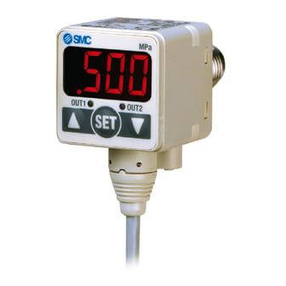
Series ISE70/75/75H
Specific Product Precautions1
Be sure to read this before handling.
Referto back page 1 forSafety Instructionsand “PrecautionsforHandling
Pneumatic Devices” (M-03-E3A) forPressure SwitchesPrecautions.
1. Do not drop, bump, orapply excessive im-
pacts(980 m/s2) while handling.
Although the body of the sensor may not be damaged, the in-
ternal parts of the sensor could be damaged and lead to mal-
function.
2. The tensile strength of the cord is 50 N.
Applying a greater pulling force on it can cause a malfunction.
When handling, hold the body of the sensor –– do not dangle it
from the cord.
3. Do not exceed the screw-in torque of 40 N·m
forthe ISE70 and 80 N·m forthe ISE75(H) when
connecting the pipe to the switch.
Exceeding these values may cause the switch to malfunction.
4. Do not use pressure sensors with poisonous,
corrosive and/orflammable gasesorliquids.
5. When connecting the pipe to the switch, enga-
ge the wrench horizontally to the chamfered
barrel of the fitting.
Be careful not to apply excessive force to the switch’s main unit.
Warning
Handling
Connection
1.
Incorrect wiring can damage the switch and cau-
se malfunction orerroneousswitch output.
2. Connectionsshould be done while the power
is turned off.
3. Wire separately from powerlinesand high vol-
tage lines, avoiding wiring in the same conduit
with these lines.
Malfunctions may occur due to noise from these other lines.
4. If a commercial switching regulatoris used,
make sure that the F.G. terminal is grounded.
Warning
Pressure Source
1. Use of poisonousand deleterioussubstances,
corrosive orcombustible fluids
Do not use fluids such as poisonous and deleterious substan-
ces or corrosive gases. Also, note that the switch is not explo-
sion-proof.
2. Applicable fluids
Do not use the switch for any corrosive or flammable gas or
fluid (ISE70 series).
Do not use the switch for any fluid capable of corroding stain-
less steel 304, 430 and 630; or for any flammable gas or liquid
(ISE75/75H series).
(For corrosiveness of fluids, consult with the manufacturer of
the fluid.)
3. Withstand pressure
When liquid fluid is used, rapid pressure change can be gene-
rated such as water hammer and surge pressure when a val-
ve is turned ON/OFF.
Install a dumper, an absorber or an accumulator as a counter-
measure according to necessity. It may damage the pressure
sensor or the switch if pressure over the proof pressure is ap-
plied even for a second.
Warning
1. Connecting the pipe to the switch
When connecting the pipe to the switch, apply a torque of
13.6 N·m or greater for the ISE70 series and a torque of 25
N·m or greater for the ISE75/75H series.
2. Bracket-mounting the switch
Interlock the neck of the switch's piping port between the bra-
cket assembly and bracket B. Using two M6 screws, mount
the switch onto a wall. If the panel thickness is less than 5
mm, use nuts or other alternative means to increase the
mounting strength.
Mounting
Caution
Bracket B
Bracket assembly
Bracket B and the bracket assembly make up one set.
OUT1
U P
SET
DOWN
Caution
1. Ourpressure switchesare CE marked; howe-
ver, they are not equipped with surge protec-
tion against lightning.
Lightning surge countermeasures should be applied directly to
system components as necessary.
2. Ourpressure switchesdo not have an explo-
sion proof rating.
Never use in the presence of an explosive gas as this may
cause a serious explosion.
Operating Environment
1. Do not use in an environ-
ment with spattering liquid
of oil orsolvent.
This may cause the switch to mal-
function due to corrosion and/or swe-
lling in the seals (FKM).
Warning
Gasket
O-ring
OUT1
U P
SET
DOWN
Back page 2
