56-EX260-TF2Z328EN
Page 1 of 2
Instruction Manual
Fieldbus device - SI unit for PROFINET
Series 56-EX260-SPN1-X42
II 3G Ex ec IIC T4 Gc -10
o
≤
≤
o
II 3D Ex tc IIIC T62oC Dc IP67
The intended use of this SI unit is for the control of pneumatic valves.
1 Safety Instructions
These safety instructions are intended to prevent hazardous situations
and/or equipment damage. These instructions indicate the level of
potential hazard with the labels of “Caution,” “Warning” or “Danger.”
They are all important notes for safety and must be followed in addition
to International Standards (ISO/IEC)*1), and other safety regulations.
*1) ISO 4414: Pneumatic fluid power - General rules relating to systems.
ISO 4413: Hydraulic fluid power - General rules relating to systems.
IEC 60204-1: Safety of machinery - Electrical equipment of machines.
(Part 1: General requirements)
ISO 10218-1: Manipulating industrial robots -Safety. etc.
•Refer to product catalogue, Operation Manual and Handling
Precautions for SMC Products for additional information.
•Keep this manual in a safe place for future reference.
Caution indicates a hazard with a low level of risk which, if
not avoided, could result in minor or moderate injury.
Warning indicates a hazard with a medium level of risk
which, if not avoided, could result in death or serious injury.
Danger indicates a hazard with a high level of risk which, if
not avoided, will result in death or serious injury.
Warning
•Always ensure compliance with relevant safety laws and
standards.
•All work must be carried out in a safe manner by a qualified person in
compliance with applicable national regulations.
II 3G Ex ec IIC T4 Gc -10oC
≤
≤
II 3D Ex tc IIIC T62oC Dc IP67
Category 3
Gas (G) and Dust (D) environment
Ex - European standards apply
ec – Increased safety
IIC - for all types of gas
T4 - Temperature classification
tc - protected by enclosure
lllC - for all types of dust
T62oC - Max. surface temperature
Gc/Dc - Equipment Protection Level
Ta - ambient temperature
IP67 - Protection structure
Based on the conformity assessment carried out by SMC Corporation.
If the Certificate number includes an X, special conditions for safe use
apply as follows:-
•Protect the product from sources of heat which can generate surface
temperatures higher than the temperature classification.
•Protect the product and cable connections against all impact or
mechanical damage using a suitable ATEX compliant enclosure.
1 Safety Instructions (continued)
•Protect the product from direct sunlight or UV light using a suitable
protective cover.
•Do not disconnect the M12 connectors before first switching off the
power supply.
•Use only ATEX approved connectors and use only shielded cable to
provide grounding.
•Use only a damp cloth to clean the product to avoid electrostatic
discharge.
2 Specifications
General specifications
35 to 85%RH (No condensate)
Ambient storage temperature
500 VAC applied for 1 minute
Electrical specifications
Communication specifications
PROFINET IO (specification version 2.3)
Transmission medium
Standard Ethernet cable (CAT5)
(100BASE
-
TX)
Class C (only for IT switch function)
Applicable function
FSU (Fast Start Up)
MRP (Media Redundancy Protocol)
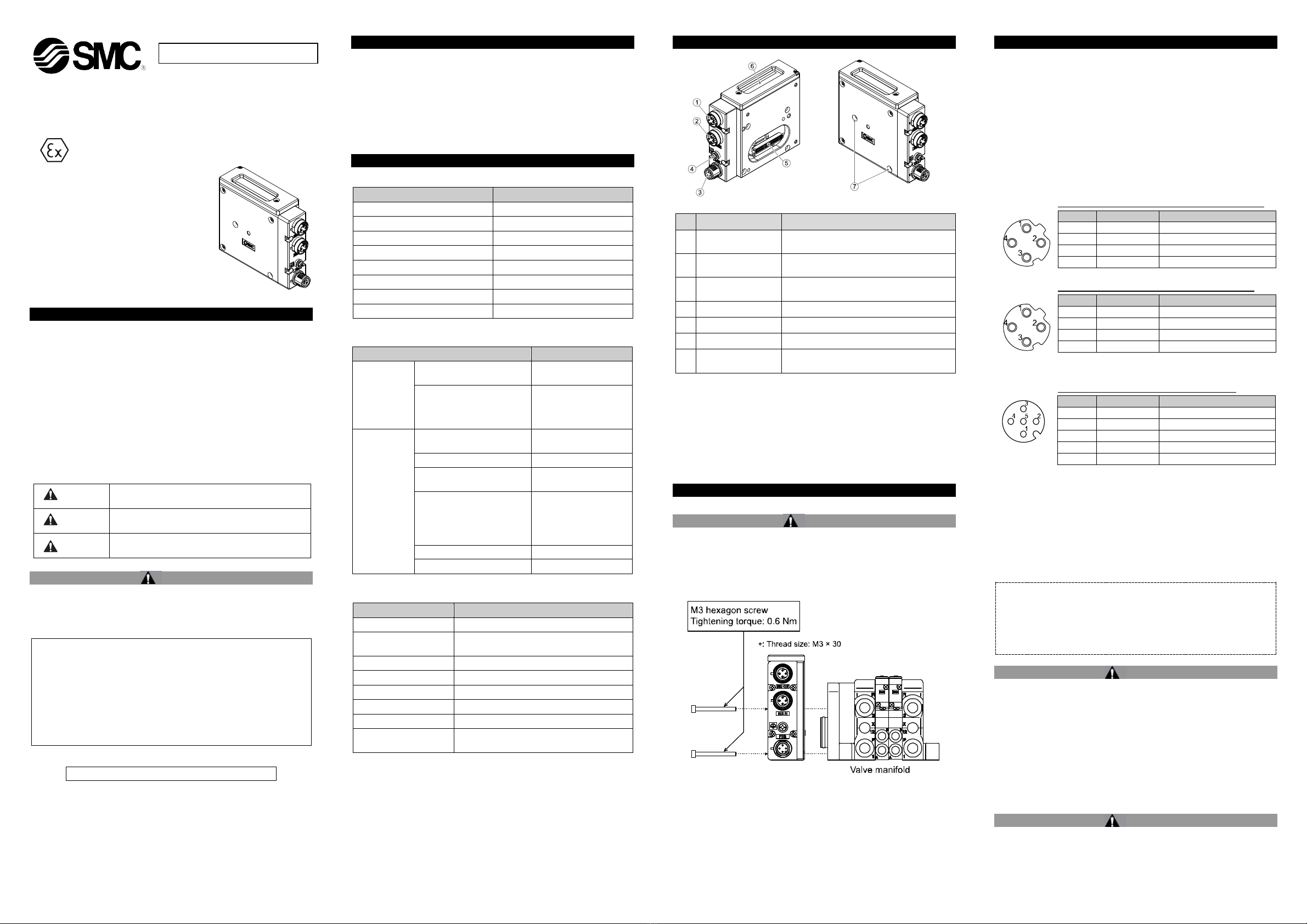
3 Name and function of Individual parts
1
Fieldbus connector
(BUS OUT)
PROFINET connection PORT2
(M12 4-pin socket, D-coded)
2
Fieldbus connector
(BUS IN)
PROFINET connection PORT 1
(M12 4-pin socket, D-coded)
3
Power supply for valves and operation of SI
unit (M12 5-pin plug, A-coded)
Output signal interface for valve manifold
Bus status specific and SI unit status LED’s
7 Mounting hole
Mounting hole for connection to the valve
manifold
4 Installation
4.1 Installation Warning
•Do not install the product unless the safety instructions have been
read and understood.
•General instructions on installation and maintenance
Connect the valve manifold to the SI unit.
•Assembly and disassembly of the SI unit
4.2 Replacement of the SI unit
•Remove the M3 hexagon screws from the SI unit and release the SI
unit from the valve manifold.
•Replace the SI unit.
•Tighten the screws with the specified tightening torque. (0.6 N•m)
4 Installation (continued)
4.3 Assembly Precautions
•Be sure to switch off the power.
•Check there is no foreign matter inside the SI unit.
•Check there is no damage and no foreign matter stuck to the gasket.
•Be sure to tighten the screws with the specified torque.
•If the SI unit is not assembled properly, the internal PCBs may be
damaged or liquid and/or dust may enter into the unit.
4.4 Connecting Cables
Select the appropriate cables to mate with the connectors mounted on
the SI unit.
○Fieldbus interface connector layout
-pin socket, D-coded (SPEEDCON)
: M12 4-pin socket, D-coded (SPEEDCON)
○Power supply connector layout
M12 4-pin plug, A-coded (SPEEDCON)
+24 V for SI unit operation
0 V for SI unit operation
•The power supply for the solenoid valve and SI unit operation are
isolated. Be sure to supply power respectively.
Either single source power or two different power supplies can be
used.
NOTE
When conformity to UL is required the SI unit must be used with a
UL1310 Class 2 power supply.
The M12 connector cable for fieldbus and power supply connections
has two types, Standard M12 and SPEEDCON compatible. If both
plug and socket have SPEEDCON connectors, the cable can be
inserted and connected by turning it a 1/2 of a rotation, leading to a
reduction in man hours.
A standard connector can be connected to a SPEEDCON connector.
Warning
•Be sure to fit a seal cap (EX9-AWTS) on any unused connectors.
Proper use of the seal cap enables the enclosure to maintain IP67
specification.
4.5 Ground Terminal
•Connect the ground terminal to ground.
•Individual grounding should be provided close to the product with a
short cable to assure the safety and noise resistance of the Fieldbus
system.
•Resistance to ground should be 100 ohms or less.
4.6 Environment Warning
•Do not use in an environment where corrosive gases, chemicals, salt
water or steam are present.
•Do not install in a location subject to vibration or impact in excess of
the product’s specifications.
Power supply
voltage range
/ current
consumption
Controller power supply
21.6 to 26.4 VDC
0.1 A max.
Solenoid valve power
supply
2.0 A or less, according
to the solenoid valve
Solenoid
valve
specification
Output type
PNP (negative common)
/ source
Output condition at the time
of communication error
Connected load
surge voltage
suppressor of 24 VDC
and 1.0 W or less


