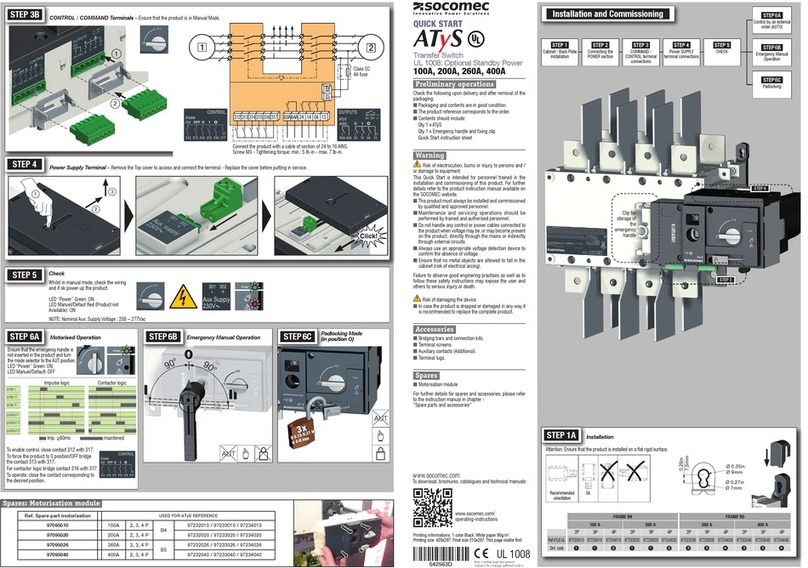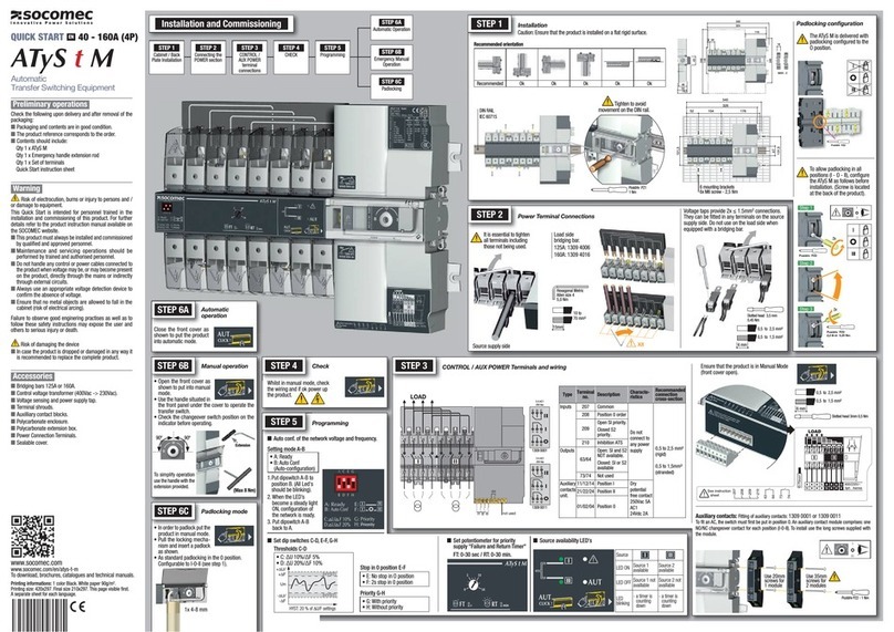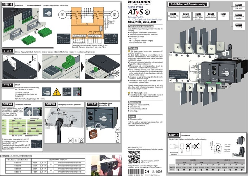
Whilst in manual mode, check the
wiring and if ok power up the
product.
LED “Power” Green: ON
LED Manuel/Defaut Red
Ensure that the emergency handle is
not inserted in the product and turn
LED “Power” Green: ON
LED Manuel/Default: OFF
___________________________________________________________
STEP 5
STEP 6A
Automatic Operation
the desired position.
Check
maintened
order I
position I
order II
position II
Contactor logicImpulse logic
Preliminary operations
packaging:
n Packaging and contents are in good condition.
n
n Contents should include:
Warning
or damage to equipment.
installation and commissioning of this product. For further
n
n
n
on the product, directly through the mains or indirectly
n
n
n In case the product is dropped or damaged in any way it
is recommended to replace the complete product.
Accessories
n
n
n
n
n
n
n
n
n
n
n Door escutcheon frame.
n
n
For further details, please refer to the instruction manual in
541 629 B - 09/13 - EN
quick start
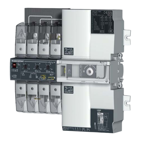
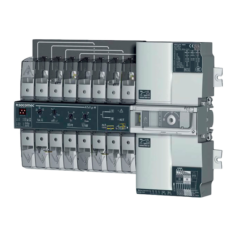
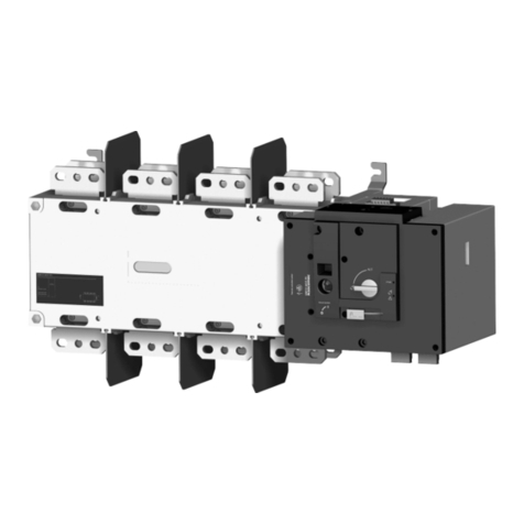
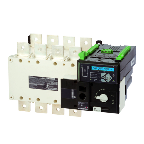
ATyS
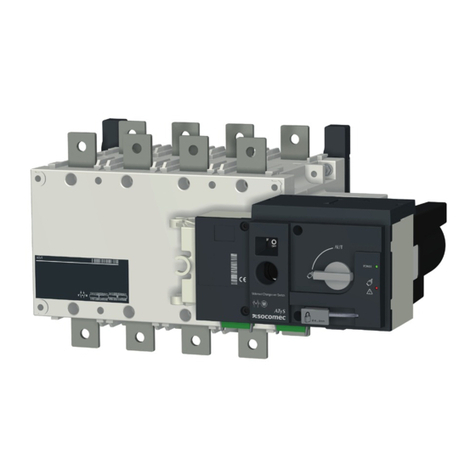
Motorised Source Changeover Switch
EN
Dimensions in mm.
125 A 160 A 200 A 250 A 315 A 400 A 500 A 630 A
3 P 4 P 3 P 4 P 3 P 4 P 3 P 4 P 3 P 4 P 3 P 4 P 3 P 4 P 3 P 4 P
J 1
M
T
C
U
W999999
CA
STEP 1
Installation
STEP 3
connections
STEP 2
Connecting the
POWER section
STEP 4
Power
terminal connections
STEP 5
CHECK
C21
M
Fix. 195
Fix. 180
==
J1
T
U
Ø7
Ø9
Fix. 180
Fix. 195
CA
W
M
Fix. 195
Fix. 180
==
J1
U
CA
W
T
U
U
STEP 1Installation and Commissioning
Non contractual document.
Subject to change without notice.
AUT
STEP6B
STEP6C
Manual Operation
Padlocking Mode
(as standard: in position O)
Clip for
storage of
the
emergency
handle
STEP 3
STEP6A
STEP6C
Padlocking
STEP6B
Emergency Manual
Operation
STEP 4
AUT
Installation
www.socomec.com
3x
Ø4-8 mm
CONTROL / COMMAND Terminals - Ensure that the product is in Manual Mode.
STEP 3
STEP 4
Power Supply Terminal -
1
2
3
.
12
3013022
312313 314315 316317 63A64A 24 14 04 13
125A-630A
1
2
Printing informations:.
CA
W
U
50.5
20
138
101
Ensure that
the product is
installed on a
flat rigid
surface.
Orientation:
OkRecommended
FRAME B3 FRAME B4 FRAME B5
125 A 160 A 200 A 250 A 315 A 400 A 500 A 630 A
tion Cu (mm
tion Cu (mm
section Cu (mm
Recommended tight
STEP 2
Power Terminal Connections
