ATyS
Transfer Switch
UL 1008: Optional Standby Power
542 563 A - 02/14 - EN
QUICK START
100A, 200A, 260A, 400A
Printing informations: 1 color Black. White paper 90g/m2.
Printing size: 420x297. Final size 210x297. This page visible first.
Non contractual document.
Subject to change without notice.
www.socomec.com
To download, brochures, catalogues and technical manuals:
http://www.socomec.com/en/
atys-ul-1008
Preliminary operations
Check the following upon delivery and after removal of the
packaging:
■ Packaging and contents are in good condition.
■ The product reference corresponds to the order.
■ Contents should include:
Qty 1 x ATyS
Qty 1 x Emergency handle and fixing clip
Quick Start instruction sheet
Warning
Risk of electrocution, burns or injury to persons and /
or damage to equipment.
This Quick Start is intended for personnel trained in the
installation and commissioning of this product. For further
details refer to the product instruction manual available on
the SOCOMEC website.
■This product must always be installed and commissioned
by qualified and approved personnel.
■Maintenance and servicing operations should be
performed by trained and authorised personnel.
■Do not handle any control or power cables connected to
the product when voltage may be, or may become present
on the product, directly through the mains or indirectly
through external circuits.
■ Always use an appropriate voltage detection device to
confirm the absence of voltage.
■ Ensure that no metal objects are allowed to fall in the
cabinet (risk of electrical arcing).
Failure to observe good enginering practises as well as to
follow these safety instructions may expose the user and
others to serious injury or death.
Risk of damaging the device
■ In case the product is dropped or damaged in any way it
is recommended to replace the complete product.
Accessories
■ Bridging bars and connection kits.
■ Terminal screens.
■ Auxiliary contacts (Additional).
■ Terminal lugs.
Spares
■ Motorisation module
For further details for spares and accessories, please refer
to the instruction manual in chapter -
"Spare parts and accessories"
STEP 1
Cabinet / Back Plate
Installation
STEP 3
COMMAND /
CONTROL terminal
connections
STEP 2
Connecting the
POWER section
STEP 4
Power SUPPLY
terminal connections
STEP 5
CHECK
Installation and Commissioning
Clip for
storage of
the
emergency
handle
STEP 3
STEP 6A
Control by an external
order (AUTO)
STEP 6C
Padlocking
STEP 6B
Emergency Manual
Operation
STEP 4
UL 1008
Whilst in manual mode, check the wiring
and if ok power up the product.
LED “Power” Green: ON
Available): ON
STEP 5
Check
Ensure that the emergency handle is
not inserted in the product and turn
the mode selector to the AUT position.
LED “Power” Green: ON
LED Manuel/Default: OFF
___________________________________________________________
STEP 6A
Motorised Operation
To enable control, close contact 312 with 317.
To force the product to 0 position/OFF bridge
the contact 313 with 317.
For contactor logic bridge contact 316 with 317.
To operate: close the contact corresponding to
the desired position.
maintened
order I
position I
order 0
position 0
order II
position II
Contactor logicImpulse logic
STEP 6C
Padlocking Mode
(in position O)
3x
Ø 4-8 mm
Ø
0.15-0.31 in
CONTROL / COMMAND Terminals - Ensure that the product is in Manual Mode.
STEP 3B
STEP 4
Power Supply Terminal - Remove the Top cover to access and connect the terminal - Replace the cover before putting in service.
1
2
3
Connect the product with a cable of section of 24 to 16 AWG.
Screw M3 - Tightening torque: min.: 5 lb-in - max. 7 lb-in.
12
301 3022
312 313 314 315 316 317 63A 64A 24 14 04 13
1
2
Class CC
4A fuse
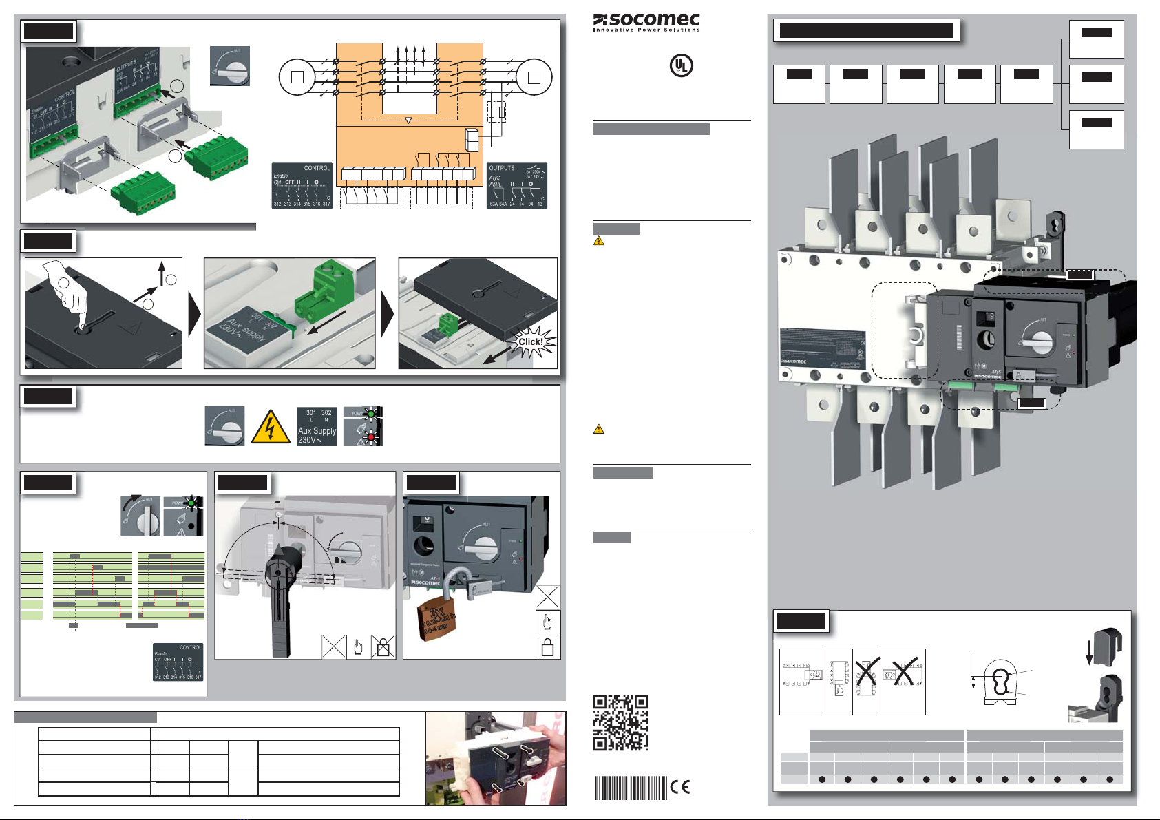
STEP 1A
Installation
Attention: Ensure that the product is installed on a flat rigid surface.
Recommended
orientation
Ok
0.29in
7,5mm
Ø 0.35in
Ø 9mm
Ø 0.27in
Ø 7mm
FRAME B4 FRAME B5
100 A 200 A 260 A 400 A
2P 3P 4P 2P 3P 4P 2P 3P 4P 2P 3P 4P
Ref ATyS UL 97232010 97233010 97234010 97232020 97233020 97234020 97232026 97233026 97234026 97232040 97233040 97234040
Dim. code
1 1 2 1 1 2 3 3 4 3 3 4
Spares: Motorisation module
AUT
90°
90°
III
0
STEP 6B
Emergency Manual Operation
AUT
AUT
Ref. Spare part motorisation USED FOR ATyS REFERENCE
97095010 100A 2, 3, 4 P
B4
97232010 / 97233010 / 97234010
97095020 200A 2, 3, 4 P 97232020 / 97233020 / 97234020
97095026 260A 2, 3, 4 P
B5
97232026 / 97233026 / 97234026
97095040 400A 2, 3, 4 P 97232040 / 97233040 / 97234040
NOTE: Nominal Aux. Supply Voltage : 208 – 277Vac


