manuals.online logo
Brands
  1. Home
  2. •
  3. Brands
  4. •
  5. SolaX Power
  6. •
  7. Inverter
  8. •
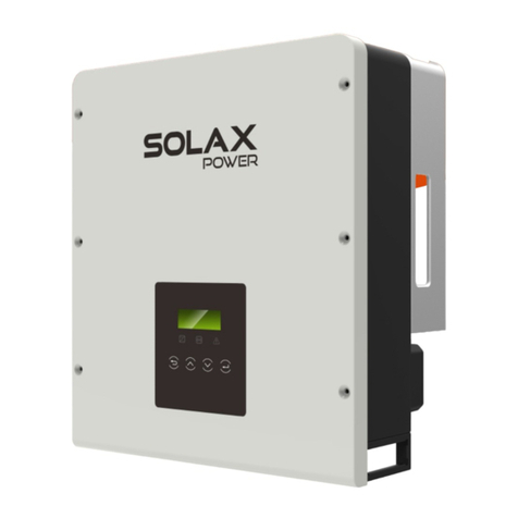
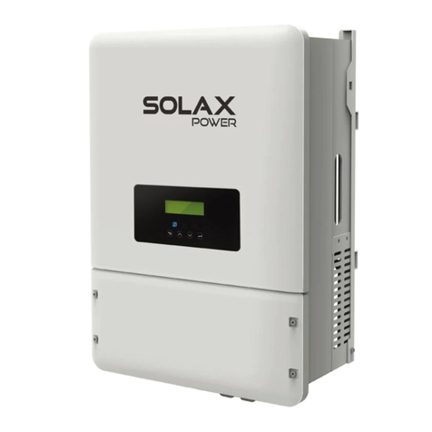
  9. SolaX Power X3-Retro Fit Series User manual

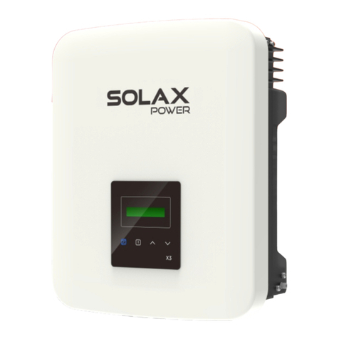
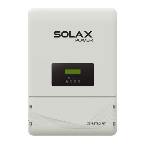
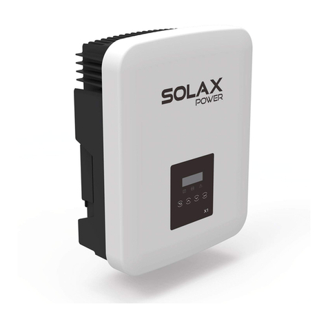
SolaX Power X3-Retro Fit Series User manual

I
Packing List
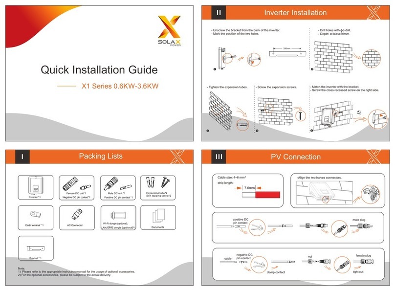
Quick Installation Guide
EPS wiring diagram
For Australia/New Zealand
For other countries
EPS connection steps:
Note: ConnectPEwire into
1. Make wire(EPS cable size: refer to table 2)
2. Insert EPS cable into EPS port through screw cap.
Note: The right most port
should not be connected !
EPS Connection(for E Version )
Communication interface bewteen inverter and battery is CAN with a RJ45
connector.
Note:
The battery communication can only work when the battery BMS iscompatible
withtheinverter.
A:Power Connection Steps:
BMS_CANH
GND BMS_485A BMS_485B
GNDNTC GND BMS_CANL
Definition
23 4 56 7 81
PIN
Press down spring until it clicks audibly into place
The ne wire strands must be seen in the champer
wire strands
Battery Connection(optional)
Before connecting to battey, please install a nonpolarized DC breaker to make
sure inverter can be securely disconnected during maintanance.
Battery breaker
Voltage
Current[A] 50A
Model X3-Fit-8.0-E X3-Fit-8.0-C X3-Fit-10.0-E X3-Fit-10.0-C
Nominal voltage of DC breaker should be larger than maximum
voltage of battery.
X3-Retro Fit 8kW-10kW
Mounting Steps
table2: Cable and Micro-breaker recommended
EPS Cable 5mm
EPS breaker
5mm 5mm 5mm
32A 32A 32A 32A
Model X3-Fit-8.0-E X3-Fit-8.0-C X3-Fit-10.0-E X3-Fit-10.0-C
E Version For Other Countries
E Version For AU/NZ
This function can be achieved manually or automatically according to
user’s preference.
For manual solution, please install an external switch.
L 1
L 2
L 3
N
P E
60mm
12mm
L 1
L 2
L 3
N
60mm
12mm
L1 L1
L2 L2
L3 L3
NN
SolaX
meter
+
-
Battery
E-BAR
Main switch
RCD
PE
SolaX X3-Retro Fit inverter
Loads
L2
L1
L2L1 L3 N
L3
N
EPS
Loads
L2L1 L3 N
RCD
N-BAR
the cable is not
required for
Australia
Changeover device with
interlocked switching
SolaX
meter
+
-
Battery
DPDT
E-BAR
Main switch
RCD
PE
SolaX X3-Retro Fit inverter
Loads
L2
L1
L2L1 L3 N
L3
N
L1 L1
L2 L2
L3 L3
NN PE
EPS
Loads
L2L1 L3 N
RCD
Australia/New Zealand other countries
Battery connection diagram
BMS PIN Denition
3.Insert AC cable into AC port
through screw cap.
a.L-wire,N-wire connection
b.PE wire connection
4. Connect the wire to the AC terminal in the inverter. 
AC connectionsteps(AC cable size:refer to table1):
1.Remove thetop-down cover.
2. Make AC wires.
Cable 4-5mm
Micro-breaker
4-5mm5-6mm5-6mm
32A 32A 32A 32A
Model X3-Fit-8.0-E X3-Fit-8.0-C X3-Fit-10.0-E X3-Fit-10.0-C
table1
60mm
12mm
L 1
L 2
L 3
N
P E
E E
EE
A
PE port at right side!
PE
(φ4hexagon wrench.torque:3±0.1Nm)
(The sleeve .torque:1.2±0.1Nm)
(One-word screwdriver.torque:1.2±0.1Nm)
(tighten torque:3.0Nm) (tighten torque:3.0Nm) (tighten torque:3.0Nm)
AC terminal X12
Grounding nut X1
Warranty card X1 Quick installation guide X1
Wifi module(optional) X1
Battery connectors
(positive X1, negative X1)
Ring terminal X2
User manual X1
NTC (optional) X1
Scope tape(optional) X1
Bracket X1 8 pin terminal X1
high-voltage lithium battery.
+
-
CAN
Nonpolarized
DC breaker
Power connection
Communication connection
B:Communication Connection Steps:
Step3: Assemble the cable gland and
screw the cable nut.
Step1: Disassemble the BMS cable gland.
Step2: Prepare a communication
cable(without sheath)and insert
the communication cable through
the cable nut.
BMS
-Mark position of five holes. - Tighten the expansion tubes.
- Drill holes with φ10 drill.
- Depth: at least 60mm.
- Screw the expansion screws. - Match the inverter with the bracket.
- Buckle the back card of the inverter back to the back of the wall.
X3- Retro Fi t User Man ual
8.0kW - 10.0kW
X3-Retro-Fi t 8kW-10kW
Expansion bolt (5) X1
Waterproof connector
with RJ45 (2*RJ45) X1
COM
(The screwdriver .torque:1.2±0.1Nm)
L1 L2 L3 N
Earth Connection&Start Inverter
Earth Connection Steps(mandatory):
Startinverter
Inverter will start up automatically when the battery is discharging.
Check the status of indicators and LCD screen. The left indicator should
be blue and the indicator screen should display the main interface.
Start Guide Monitoring Operation
Cable size: 12AWG.
ring terminal
Meter Connection
English
Deutsch
Language
Country
VDE0126
Safety
Mode Select
> self use <
Work Mode
1.Set language 2.Set date time 3.Set the safety standard
This function allows the inverter able to control energy exported to the grid.
There are user value and factory value. The factory value is default which can not be charged
by user. The user value setting by installer must be less than the factory value.
4.Set export control
5.Set work mode
There are 4 work modes for choice.
Self use/
Back up mode/
Feed in Priority/
Force Time Use
6.Set EPS system(For E Version only)
X3-Retro Fit inverter with E Version can work on the EPS mode.
EPS parameters can be set as below.
- “Mute”means you can set the warning of system which has entered EPS mode.
- ”No”means there will be a buzzing and it is the default value.
- ”Yes”means you choose to shut down the warning function.
Besides ,if the buzzing is sharp, it means EPS output is over loads.“
Frequency “here can be set 50Hz or 60Hz please based on correlative loads.
1) Insert L/N wires and the 485cable
into the meter.
Meter connection step
To grid-L
To inverter-L
To grid-N
To inverter-N
485A
485B
7 111
36 9
1516
4
3
14711
69
Meter connection diagram
User value:
Export Control
4000W
Battery will stop discharing to keep higher capacity when the
grid is on. Only when the gird is off and PV energy is not
enough, battery will start to discharge to keep the emergency
load working normally.
This work mode applies to the area where suffering from
blackout regularly.
The priority of inverter output power is:
supplying the load feeding to the grid charging the
battery.
This work mode applies to the area with high feed-in tariff.
Self Use
(default)
Force Time Use
Back Up Mode
Feed in Priority
The external generator generated power will be used to supply
the local loads firstly, then to charge the battery. The redundant
power will export to the public grid.
When there is no external generator supplied, battery will
discharge for local loads firstly, and grid will supply power when
the battery capacity is not enough.
In this work mode the charging and discharging time can be set
flexibly, and it also allows to select whether charge from the grid
or not.
Parameter Comment
c. Insert connection into corresponding Meter terminal inside of the
inverter.(Torque:0.4±0.1Nm)
a. Unscrew the cable nut of Meter connector and insert two
communication wires through it.
b. Trip the insulation from the communication cable, and then
insert it into connector.(Torque:0.2±0.1Nm)
wires 485A
485B
Firmware Upgrading
Please ensure the inverter is steadily powered on. Inverter must keep the battery on through whole procedure of upgrading. Please prepare a PC and
an U-disk.
Preparation
Warning!
Make sure the battery voltage is more than 180V , otherwise it may result in serious failing during upgrading.
1) Please contact our service support to get the update les, and extract itintoyourU-disk as following: 
2) Press the “Enter” key for 5 seconds to enter Off Mode. Then unscrew the waterproof lid and insert U-disk into the “upgrade” port at the
bottom of the inverter.
“update\ARM\618.00098.00_Hybrid_X3G3_Manager_VX.XX_XX-XX.usb”;
“update\DSP\618.00096.00_Hybrid_G3X3_Master_VX.XX_XX-XX.hex”;
3) The LCD will be shown as the picture. Then press up and down to select the one that you want to upgrade and press “OK” to confirm to
upgrade.
>ARM
4) After the upgrade is finished, the LCD will display “succeed”(only for DSP upgrades), please remember to pull off the U-disk, screw the
waterproof lid and press the “Esc” to return to the Main interface. Then press the “Enter” key to exit Off Mode.
U-disk
Update
DSP
Update(ARM)
Updating---------25%
614.00456.01
Solax provides two ways for users to choose: WiFi(optinal) and RS485
Inverter provides a WiFi port which can collect data from inverter and transmit it to monitoring-website via a Pocket WiFi.
(Purchase the product from supplier if needed)
Diagram
Could
Router
WiFi Connection Steps:
Step3. Create an user account online.( Please check the Pocket WiFi user
manual for more details.)(PH1 cross screwdriver .torque:1.5±0.1Nm)
Step1. Plug Pocket WiFi into “WiFi” port at the bottom of the inverter.
Step2. Build the connection between the inverter and router.
WiFi(optinal)
Communication interface bewteen inverter and router is RS485
with a RJ45 connector.
COM PIN Definition
Application Occasion
COM is one standard communication interface which
can transmit the real data from inverter to PC or other
monitoring equipments.
X
XGND 485A 485B X X X
123 4 56 7 8
1
8
COM
COM communication interface, which can be upgraded to man-machine communication interface.Output voltage, current, frequency,
fault information and other operational information can be transferred to PC or other monitoring equipment through these interfaces.
2) Insertthe other side of the cable into the meter port on the
inverter.
SolaX
meter
+
-
Battery
DPDT
E-BAR
Main switch
RCD
PE
SolaX X3-Retro Fit inverter
Loads
L2
L1
L2L1 L3 N
L3
N
L1 L1
L2 L2
L3 L3
NN PE
EPS
Loads
L2L1 L3 N
RCD
1
36
2
5
6
4
6
7
Turn on the AC switch, EPS switch and battery switch.
Press the “Enter” key for five seconds to exit Off Mode. (The mode is factory
defaulted as Off Mode)
Make sure the external EPS contactor is connected well. (if needed)
Make sure the battery is connected well.
Make sure the meter is connected well.
Make sure all the AC wirings are completed.
Ensure the inverter fixed well on the wall.
E
(φ4hexagon wrench.torque:1.5±0.2Nm)
>2013 - 06 - 06
10 : 19
Date time
> Mute: No
Frequency: 50Hz
EPS auto restart
EPS system
Electrical
grid
Home Electric meter,
Three phase
meter
Load
Meter connection(RS485)
L
N
Communication interface bewteen inverter and meter is RS485 with
a Green terminal.
COM Connection Steps:
RS485 Port
Please refer to BMS connection steps (for user manual page32) for COM connection. Please kindly noted the PIN definition and port
position will be slightly different.
RS 485
COM
CO M
485B485A
485A 485B Torque:0.4±0.1Nm
Torque:0.2±0.1Nm
Other manuals for X3-Retro Fit Series

4

Other SolaX Power Inverter manuals

SolaX Power A1-Hybrid Series User manual

SolaX Power

SolaX Power A1-Hybrid Series User manual

SolaX Power X1-Hybrid User manual

SolaX Power

SolaX Power X1-Hybrid User manual

SolaX Power X1-EVC Series User manual

SolaX Power

SolaX Power X1-EVC Series User manual

SolaX Power X-Hybrid SK-BMU User manual

SolaX Power

SolaX Power X-Hybrid SK-BMU User manual

SolaX Power X3-Retro Fit Series User manual

SolaX Power

SolaX Power X3-Retro Fit Series User manual

SolaX Power ZDNY Series User manual

SolaX Power

SolaX Power ZDNY Series User manual

SolaX Power X3-FORTH Series User manual

SolaX Power

SolaX Power X3-FORTH Series User manual

SolaX Power X1 Series User manual

SolaX Power

SolaX Power X1 Series User manual

SolaX Power Solax Box 3.0 User manual

SolaX Power

SolaX Power Solax Box 3.0 User manual

SolaX Power X1-Fit-3.7C User manual

SolaX Power

SolaX Power X1-Fit-3.7C User manual

SolaX Power X1-MINI-G4 Series User manual

SolaX Power

SolaX Power X1-MINI-G4 Series User manual

SolaX Power X3-Series User manual

SolaX Power

SolaX Power X3-Series User manual

SolaX Power ZDNY-TL Series User manual

SolaX Power

SolaX Power ZDNY-TL Series User manual

SolaX Power X3-Matebox User manual

SolaX Power

SolaX Power X3-Matebox User manual

SolaX Power X3-Matebox advanced User manual

SolaX Power

SolaX Power X3-Matebox advanced User manual

SolaX Power X1 Series User manual

SolaX Power

SolaX Power X1 Series User manual

SolaX Power X3-MIC G2 Series User manual

SolaX Power

SolaX Power X3-MIC G2 Series User manual

SolaX Power X3-ULTRA User manual

SolaX Power

SolaX Power X3-ULTRA User manual

SolaX Power X1-Matebox User manual

SolaX Power

SolaX Power X1-Matebox User manual

SolaX Power X3-MEGA G2 Series User manual

SolaX Power

SolaX Power X3-MEGA G2 Series User manual

SolaX Power T-BAT H 11.5 User manual

SolaX Power

SolaX Power T-BAT H 11.5 User manual

SolaX Power BMS-PARALLEL BOX-II User manual

SolaX Power

SolaX Power BMS-PARALLEL BOX-II User manual

SolaX Power X3-Fit-8.0-E User manual

SolaX Power

SolaX Power X3-Fit-8.0-E User manual

SolaX Power X3-Hybrid Series User manual

SolaX Power

SolaX Power X3-Hybrid Series User manual

Popular Inverter manuals by other brands

Yiyuan Electric AP Series user manual

Yiyuan Electric

Yiyuan Electric AP Series user manual

YOUESS U Series user manual

YOUESS

YOUESS U Series user manual

Fimer UNO-DM-6.0-TL-PLUS-US-Q product manual

Fimer

Fimer UNO-DM-6.0-TL-PLUS-US-Q product manual

TBB Kinergier Pro Series user manual

TBB

TBB Kinergier Pro Series user manual

Outback ProHarvest 208V quick start guide

Outback

Outback ProHarvest 208V quick start guide

Hama Schuko 00089299 operating instructions

Hama

Hama Schuko 00089299 operating instructions

ZUCCHETTI 1.1K-3K TL user manual

ZUCCHETTI

ZUCCHETTI 1.1K-3K TL user manual

GYS Gysflash 70-24 HF manual

GYS

GYS Gysflash 70-24 HF manual

Agilent Technologies PSG Series Installation note

Agilent Technologies

Agilent Technologies PSG Series Installation note

Battery Supplies AQ-TRON SOL/AQT1H3M1 user guide

Battery Supplies

Battery Supplies AQ-TRON SOL/AQT1H3M1 user guide

Omron SYSDRIVE RV Series user manual

Omron

Omron SYSDRIVE RV Series user manual

THOR TH225 Instruction manual and  warranty information

THOR

THOR TH225 Instruction manual and warranty information

Mecc Alte ECP3 Series Operating and maintenance instructions

Mecc Alte

Mecc Alte ECP3 Series Operating and maintenance instructions

TECO SPEECON 7200GS manual

TECO

TECO SPEECON 7200GS manual

Morningstar SureSine 150 W quick start guide

Morningstar

Morningstar SureSine 150 W quick start guide

Jntech JNF1KLF-A/24V user manual

Jntech

Jntech JNF1KLF-A/24V user manual

SolarEdge SE3000US installation guide

SolarEdge

SolarEdge SE3000US installation guide

gefran SIEIDrive ADL300 Safety user manual

gefran

gefran SIEIDrive ADL300 Safety user manual

manuals.online logo
manuals.online logoBrands
  • About & Mission
  • Contact us
  • Privacy Policy
  • Terms and Conditions

Copyright 2025 Manuals.Online. All Rights Reserved.