manuals.online logo
Brands
  1. Home
  2. •
  3. Brands
  4. •
  5. Solinst
  6. •
  7. Measuring Instrument
  8. •
  9. Solinst 104 User manual

Solinst 104 User manual

Sonic Water Level Meter Instructions
High Quality Groundwater and Surface Water Monitoring Instrumentation
(Page 1 of 4)
Model 104
Operating Principles
The Solinst Sonic Water Level Meter consists of a Control
Unit and Probe. The Control Unit has a display, keypad, and
comes with 6 AA alkaline batteries. The Probe contains a
sound/pulse generator, microphone and temperature sensor.
The Sonic Water Level Meter works by the Probe transmitting a
sound wave into the pipe, tube, or well and measuring the time
it takes for the pulse to return after making contact with water.
The depth to water is calculated using the speed of sound and
time. Since the speed of sound varies with temperature, the
temperature sensor located in the Probe adjusts for variations.
IMPORTANT
• The Sonic Water Level Meter Control Unit and
Probe are not waterproof. They are resistant to rain or
splashing, but can not be submerged.
Equipment Check and Setup
1. Connect the Probe to the Control Unit by plugging the
Probe cable connector into the connection on the side of the
Control Unit. Ensure the connector is completely pushed in.
2. Press the ON button. The Sonic WLM Version number
should briefly display and then show “Depth* Searching”.
There should be a popping sound from the Probe, if not,
ensure the Probe is plugged in properly. Turn the Sonic
Water Level Meter OFF by pressing the button.
3. Insert the Probe into the open well casing (less than 8" dia.),
or drop tube, and then cover any open area around the
Probe to stop the sound pulse from leaving the well. For
example, use the plastic disc that is supplied with the Solinst
Sonic Water Level Meter.
Notes: 1. The seal around the probe does not need to be
airtight, but the signal works better if there is a
proper seal keeping the pulse inside the well. It
also helps keep out external noise, including wind.
2. If the top of the well or pipe is open, then it
should be covered with a cap with a hole for the
probe to access. The included plastic disc from
Solinst is a good option.
3. For highest accuracy, insert the Probe into open
well casings less than 8" in diameter. Otherwise,
use a 1/2" up to 2" diameter drop tube from top
of well to just below the water level surface to
avoid any disruptions to the sound pulse.
Water Level Measurement
1. Press the ON button on the Control Unit. “Depth*
Searching” will be displayed as it obtains a stable depth to
water reading. The depth to water measurement will be
displayed after a few seconds.
2. To ensure the accuracy of the reading, use the Control Unit
to enter specific well details such as drop tube diameter
and the minimum and maximum water level measurement
range. See the following sections for setting up these, and
other parameters.
Note: For the most accurate depth to water measurements, the
water level measurement range minimum and maximum,
and water temperature should be set.
3. Press the ON button (or the Read button if already on).
During or after “Depth* Searching” is displayed, press the
down arrow to show the battery voltage.
Note: Batteries should be replaced at 6.5 volts.
More Info | Instructions | Get Quote
Available Set Modes:
When the Set button is pressed, the Sonic WLM version number
is displayed. Press the down arrow to read the Serial Number of
the Sonic Water Level Meter.
WL Range Min (m/ft): Set the minimum range to start detecting.
Setting a minimum range can also help ignore interferences at
a specific depth. E.g. if the well casing ends at 10 m and your
water level is below that at about 20 m, then the minimum range
could be set to 15 m to ignore any reflection at 10 m. See “Well
Obstruction” and “Depth to Water” considerations.
WL Range Max (m/ft): Set the maximum depth from which
the Probe will listen for a returning pulse. If the approximate
depth to water is known, don’t set the Meter to listen for the
returning pulse longer/deeper than required. A longer range
gives less frequent returning pulses and increases the possibility
of interference. A shorter range means more frequent pulses
returning to the probe. See “Depth to Water” considerations.
In general, knowing the approximate water level before
measuring allows you to set a minimum depth to start
detecting, and a maximum depth to listen for the returning
pulse. E.g. if depth to water is usually between 8–9 m, set
your minimum to 7 m and your maximum to 10 m for
higher accuracy.
Water Temp (ºC/ºF): Manually set the estimated temperature of
the water inside your well. With the air temperature automatically
detected by the sensor in the Probe, the two temperatures are
used to calculate the speed of sound and therefore, the distance.
Note: The distance error is small for variations in temperature,
about 1% for a 10 ºF (5.6 ºC) temperature error.
Drop Tube Dia (cm/in): Set the drop tube diameter. This
compensates for a reduced sound speed in tubes smaller than
5 cm (2") in diameter. The options for this setting are:
>5 cm, 5 cm, 4.4 cm, 3.8 cm, 3.2 cm, 2.5 cm, 1.9 cm and
1.3 cm (>2", 2", 1.75", 1.5", 1.25", 1", 0.75", 0.50").
MP Offset (cm/in): Set the offset of the probe position from
ground level – the zero point is the tip of the Probe. E.g. if the
probe is inserted into a well cap that extends 75 cm above the
ground. Then enter 75 cm for the offset. This will automatically
be deducted from the depth reading. The value can be negative if
the probe is installed on a casing below ground level.
Units: Select the measurement system for the data. The options
are Metric for meters, centimeters, and degrees Celsius, or Eng ft
for feet, inches, and degrees Fahrenheit.
Power Mode: Set in Normal or Power save mode. When in
Normal mode there is an auto off after 15 minutes. When in
Power save mode, there is an auto off after 3 minutes.
Contrast: Set the contrast level on the LCD screen from
0 (brightest) to 10 (dimmest).
Factory Reset: Sets the Control Unit back to the factory default
configuration. Press the up button to make the selection. All
settings will be set to the default values in Metric.
Setting Measurement Parameters
1. Press the Set button repeatedly to scroll through the various
settings (see page 2 for available set modes).
2. Use the up and down arrow buttons to change a setting.
3. When the desired setting is reached, press the Set button
to save and advance to the next setting, or press Read to
display the depth to water measurement.
High Quality Groundwater and Surface Water Monitoring Instrumentation
Sonic Water Level Meter Instructions
Other Operating Considerations
Well Opening
The pulse generated by the Probe is an air pressure
wave/low frequency sound wave. This is why there
should be a good seal around the probe to prevent
the air pressure from escaping an opening, which
would result in not enough of the pulse going down
the well. A good seal also prevents external noise,
such as wind, from interfering with the signal.
Well Obstructions
The sound wave travels until it is disturbed. Each
time it is disturbed by an imperfection in the well,
some of the pulse is reflected, making the main pulse
a little weaker. A complete imperfection, like the
surface of the water, will reflect the entire remaining
wave. Smaller obstructions, like tubing or wires, will
not obstruct the pulse enough to affect the water
level reading. However, larger interferences such
as a small change in casing diameter, could reflect
enough of the pulse to generate an erroneous
reading. Setting a minimum detection range is
helpful to ignore such interferences.
A drop tube should be used if there are more
significant disturbances in the well, such as a large
step-down in well casing diameter or perforated
casing sections.
Depth to Water
The sound wave loses energy as it travels, and
even more if the well casing is rough or porous. To
compensate for this, the Probe increases its gain
with time to listen for fainter signals. This can cause
problems if the Probe listens for too long. The gain
will get so high that pump noise or noise outside
the well could outweigh the pulse. Therefore, the
maximum range setting is available to tell the Probe
how long to listen. E.g. if a pump is installed at 50 m,
then set a maximum range of less than 50 m to
avoid any interference from that depth.
In shallow wells, the sound wave bounces off the
top and bottom of the well, so the pulse can bounce
back and forth many times. E.g. in a well where
the water level is at 2 m, the Probe would hear
a reflection at 2 m, then again at 4 m, then 6 m
etc., until the pulse gets weak enough to ignore. In
this example, you would be able to see the multiple
reflections by increasing the minimum range. When
set to 3 m, the depth would read 4 m. When set
to 5 m, it would read 6 m, etc. In this case, it may
be helpful to leave a small leak at the probe to help
dissipate the pulse.
Well Diameter
As well diameter increases, the strength of the
sounds pulse weakens, therefore it is more
susceptible to pump noise or interference from
other imperfections. As such, wells larger than 8"
in diameter should use a drop tube from top of well,
to just below the depth to water for measurement.
Well Openings
Well Obstructions
Depth to Water
High Quality Groundwater and Surface Water Monitoring Instrumentation
Sonic Water Level Meter Instructions
Solinst Canada Ltd. 35 Todd Road, Georgetown, Ontario Canada L7G 4R8 www.solinst.com
E-mail: [email protected] Tel: +1 (905) 873-2255; (800) 661-2023 Fax: +1 (905) 873-1992
March 1, 2021
(#115723) (Page 4of 4)
Troubleshooting
SYMPTOM CAUSE REMEDY
Will not power on /
Display is blank
Contrast of the Control Unit is too
low.
If the Probe makes the normal “popping” sound when powered on, but nothing
is displayed, check the contrast of the Control Unit screen. You may be able
to see the screen in a different lighting condition to adjust it. If this still does
not work, a hard reset can be done by removing one of the AA batteries and
waiting a few minutes before reinstalling.
Control Unit needs a reset. Remove the Probe connector, reconnect and try again.
Batteries need replacing. Replace the 6 AA batteries in the Control Unit.
Powers up, but no Probe
“pop”
A bent connector pin, damaged
cable or Probe.
Check the Probe cable connection rst, then contact Solinst for more options.
Erratic depth, an asterisk
beside the depth
reading, or reads “Depth*
Searching” for more than
15 seconds.
Probe not connected properly, a bent
connector pin, damaged cable or
Probe.
If there is no Probe “pop’ heard, check the Probe cable connection rst, then
contact Solinst for more options.
The well is not closed tightly enough. Ensure the well is closed and that there is a good seal around the Probe.
There is perforated casing,
incomplete inner casing, excessive
pump noise.
Try using a drop tube, or adjusting the parameter settings.
The maximum or minimum range
settings are not set properly.
Try resetting the parameters.
Other parameters or settings are
incorrect.
Try a Factory Reset.
The depth reading seems
too small.
You set the minimum range too
small.
Try adjusting the minimum range parameter.
There is an obstruction or opening in
the well.
Set a minimum range to ignore the obstruction or opening at that depth.
Display reads “no probe” Probe not connected properly, a bent
connector pin, damaged cable or
Probe.
Check the Probe cable connection rst, then contact Solinst for more options.
Maintenance
Batteries and power: The 6 AA batteries should be replaced
at 6.5 V. Old batteries should be removed as soon as possible to
prevent damage from leaking. To access the batteries, undo the
screw from the back of the Control Unit and remove the battery
cover and batteries. Ensure the new batteries are installed in the
correct polarity, as labeled. Do not kink or damage the ribbon
cable inside the Control Unit and be careful when reinstalling
the battery cover.
If the Control Unit is going to be stored for longer than a two
month period, the 6 alkaline batteries should be removed to
avoid any potential leakage.
Factory Reset: It is good practice to perform a Factory Reset
before starting a new application, or at a minimum, once a
month. A Factory Reset will default measurements to Metric.

Other Solinst Measuring Instrument manuals

Solinst 101B User manual

Solinst

Solinst 101B User manual

Solinst 122M User manual

Solinst

Solinst 122M User manual

Solinst Levelogger Series User manual

Solinst

Solinst Levelogger Series User manual

Solinst 401 User manual

Solinst

Solinst 401 User manual

Solinst 9700 SolSat 5 User manual

Solinst

Solinst 9700 SolSat 5 User manual

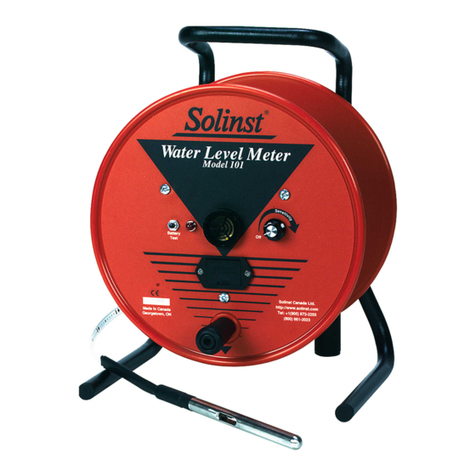
Solinst 101 User manual

Solinst

Solinst 101 User manual

Solinst 101 Operating and safety instructions

Solinst

Solinst 101 Operating and safety instructions

Solinst 101 User manual

Solinst

Solinst 101 User manual

Solinst 102 Operating and safety instructions

Solinst

Solinst 102 Operating and safety instructions

Solinst 101 Operating and safety instructions

Solinst

Solinst 101 Operating and safety instructions

Solinst 102M User manual

Solinst

Solinst 102M User manual

Solinst 101 P7 User manual

Solinst

Solinst 101 P7 User manual

Solinst 101 P2 User manual

Solinst

Solinst 101 P2 User manual

Solinst 102 Operating and safety instructions

Solinst

Solinst 102 Operating and safety instructions

Solinst 107 Mk2 User manual

Solinst

Solinst 107 Mk2 User manual

Solinst 201 User manual

Solinst

Solinst 201 User manual

Solinst 101 P7 SC1000 User manual

Solinst

Solinst 101 P7 SC1000 User manual

Solinst 101 User manual

Solinst

Solinst 101 User manual

Solinst 122 User manual

Solinst

Solinst 122 User manual

Solinst 102M User manual

Solinst

Solinst 102M User manual

Solinst Levelogger 3001 User manual

Solinst

Solinst Levelogger 3001 User manual

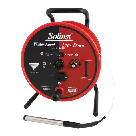
Solinst 101D User manual

Solinst

Solinst 101D User manual

Solinst Levelogger 3001 Use and care manual

Solinst

Solinst Levelogger 3001 Use and care manual

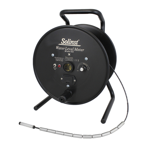
Solinst 102 User manual

Solinst

Solinst 102 User manual

Popular Measuring Instrument manuals by other brands

Klein Tools CL450 instruction manual

Klein Tools

Klein Tools CL450 instruction manual

KERN TMBA-A01-A operating manual

KERN

KERN TMBA-A01-A operating manual

Kikusui PLZ-4WH Series user manual

Kikusui

Kikusui PLZ-4WH Series user manual

SICK FLOWSIC600 operating instructions

SICK

SICK FLOWSIC600 operating instructions

Siemens SITRANS RD300 operating instructions

Siemens

Siemens SITRANS RD300 operating instructions

YOKOGAWA WN100 user manual

YOKOGAWA

YOKOGAWA WN100 user manual

ETAS ES800 user guide

ETAS

ETAS ES800 user guide

Triplett SL600-KIT user manual

Triplett

Triplett SL600-KIT user manual

janitza UMG 604 operating manual

janitza

janitza UMG 604 operating manual

Keithley 7999-4 instruction manual

Keithley

Keithley 7999-4 instruction manual

Xylem WTW Turb 750 T operating manual

Xylem

Xylem WTW Turb 750 T operating manual

Logitech Electronics 2000 MKII Series user guide

Logitech Electronics

Logitech Electronics 2000 MKII Series user guide

DeWalt DW040 user manual

DeWalt

DeWalt DW040 user manual

Hanna Instruments HI 97500 instruction manual

Hanna Instruments

Hanna Instruments HI 97500 instruction manual

Trotec SL300 operating manual

Trotec

Trotec SL300 operating manual

3M 965DSP/SA instruction manual

3M

3M 965DSP/SA instruction manual

R&S Vibracap Instructions for use

R&S

R&S Vibracap Instructions for use

PROVA 21 user manual

PROVA

PROVA 21 user manual

manuals.online logo
manuals.online logoBrands
  • About & Mission
  • Contact us
  • Privacy Policy
  • Terms and Conditions

Copyright 2025 Manuals.Online. All Rights Reserved.