manuals.online logo
Brands
  1. Home
  2. •
  3. Brands
  4. •
  5. Solinst
  6. •
  7. Measuring Instrument
  8. •
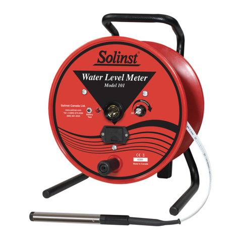
  9. Solinst 101 User manual

Solinst 101 User manual

High Quality Groundwater and Surface Water Monitoring Instrumentation
(Page 1 of 2)
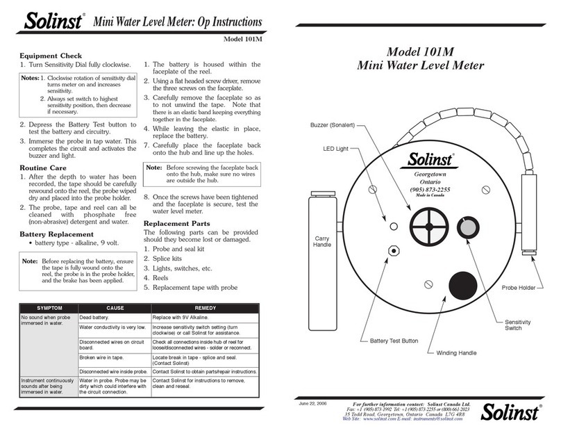
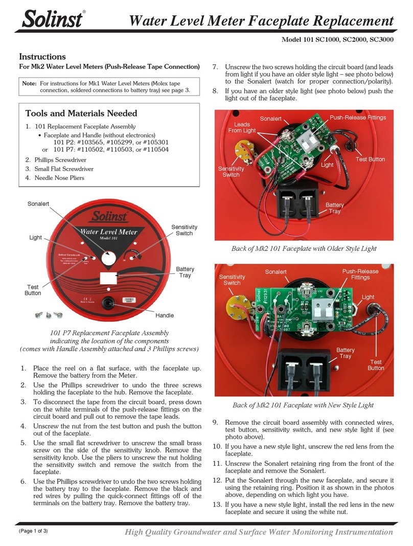
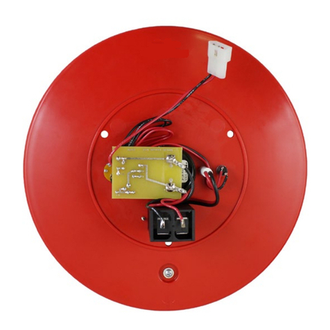
Power Reel Control Box Assembly Replacement
Model 101 12V Power Reel
Continued overleaf...
Tools and Materials Needed
1. 101 12V Power Reel Control Box Assembly for
Water Level Meter (Spare) (#111427), Includes:
• Control Box Assembly with Power Cord and Mounting Bracket
• 2 x Butt Splice Crimp Terminals
• 1 x Ring Terminal
• 4 x Cable Ties
2. Wire Cutter and Stripper
3. 7/16" Hex Wrench
4. Phillips Screwdriver
5. Adjustable Wrench (to 1-1/2")
6. Crimping Tool (see photo on page 2)
Instructions
1. Disconnect the Power Reel from the power source.
2. To remove the Control Box, cut the motor cord and power cord
from the old Control Box.
3. Use the 7/16" hex wrench to remove the four retaining nuts from
each corner of the Control Box mounting bracket. Remove the
Control Box.
4. If you would like to re-use the mounting bracket, flip the Control
Box over. Use the Phillips screwdriver to remove the four screws
from the mounting bracket, and remove it from the Control Box.
5. Mount the new Control Box to the Power Reel, using either the
attached mounting bracket, or remove and use the old mounting
bracket shown above (if applicable).
Note: The Replacement Control Box Assembly comes with a mounting
bracket attached, but can be removed, and the old mounting
bracket used in its place.
Old Style
Mounting Bracket
(Prior to Oct., 2012)
Mounting Bracket
Connects Here
Old Style
Mounting Bracket
Connects Here
6. Reuse the four nuts, bolts, and washers to secure the Control Box
to the Power Reel, using either the current style mounting bracket
that comes with the replacement assembly, or the old style bracket.
See photo below for connections.
7. Use the Phillips screwdriver to open the panel on the bottom of the
motor.
Newer Style
Mounting Bracket
(After Oct., 2012)
Printed in Canada
August 29, 2014
(#111428)
(Page 2 of 2)
For further information contact: Solinst Canada Ltd.
Fax: +1 (905) 873-1992; (800) 516-9081 Tel: +1 (905) 873-2255; (800) 661-2023
35 Todd Road, Georgetown, Ontario Canada L7G 4R8
Web Site: www.solinst.com E-mail: [email protected]
®Solinst is a registered trademark of Solinst Canada Ltd.
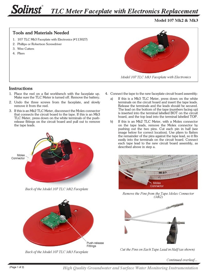
8. Use the Phillips screwdriver to undo the screw holding the green
wire to the motor.
9. Pull the wires out from the motor. Use the wire cutters to cut the
red and black wires in the motor from the black and white wires
of the motor cord. Cut the wires as close to the butt splice crimp
terminals as possible.
10. Use the adjustable wrench to undo the strain relief nut around the
cable, and pull the cable to remove the old motor cord.
11. Put the new motor cord through the strain relief.
12. Strip each of the wires by 10 mm, as shown below.
Cut Wires Here
Remove Screw
Molex Crimp Tool Options (16-14 AWG)
Use 16-14 AWG
position of tool
Recommended:
Molex 64106-0037 (Solinst #110729)
Alternative Tool
13. Insert the green wire into the new ring terminal. Use the crimping
tool to crimp the ring terminal to the green wire. Ensure a good
connection.
14. Insert the white and red wires into the ends of one of the butt splice
crimp terminals. Ensure they are inserted as far as possible into the
terminal. Use the crimping tool to secure the wires in the butt splice
crimp terminal. Ensure a good connection.
15. As above, crimp the black wires together using the other butt splice
crimp terminal. Ensure a good connection.
16. Connect the green wire to the motor using the screw, as shown in
the photo at top left.
17. Carefully tuck all wires into the motor and re-secure the panel.
18. Tighten the strain relief around the new motor lead.
Loosen the
Strain Relief Nut
19. Use the four cable ties to secure the power cord to the frame, as
shown in the photo below.
20. Once you are sure all correct connections have been made, and
that they are very secure, test the new Control Box (see 12V Power
Reel Operating Instructions).

Other Solinst Measuring Instrument manuals

Solinst 104 User manual

Solinst

Solinst 104 User manual

Solinst 101M User manual

Solinst

Solinst 101M User manual

Solinst 101 User manual

Solinst

Solinst 101 User manual

Solinst 9700 SolSat 5 User manual

Solinst

Solinst 9700 SolSat 5 User manual

Solinst 102M User manual

Solinst

Solinst 102M User manual

Solinst Levelogger 3001 Use and care manual

Solinst

Solinst Levelogger 3001 Use and care manual

Solinst 101 Parts list manual

Solinst

Solinst 101 Parts list manual

Solinst 102 User manual

Solinst

Solinst 102 User manual

Solinst 122 User manual

Solinst

Solinst 122 User manual

Solinst 101 P7 User manual

Solinst

Solinst 101 P7 User manual

Solinst 102 Operating and safety instructions

Solinst

Solinst 102 Operating and safety instructions

Solinst 201 User manual

Solinst

Solinst 201 User manual

Solinst 101 P7 SC1000 User manual

Solinst

Solinst 101 P7 SC1000 User manual

Solinst 122M User manual

Solinst

Solinst 122M User manual

Solinst 107 Guide

Solinst

Solinst 107 Guide

Solinst 107 Mk2 User manual

Solinst

Solinst 107 Mk2 User manual

Solinst 122M User manual

Solinst

Solinst 122M User manual

Solinst Levelogger 3001 User manual

Solinst

Solinst Levelogger 3001 User manual

Solinst 101 Operating and safety instructions

Solinst

Solinst 101 Operating and safety instructions

Solinst 101 Operating and safety instructions

Solinst

Solinst 101 Operating and safety instructions

Solinst 401 User manual

Solinst

Solinst 401 User manual

Solinst LevelSender 5 User manual

Solinst

Solinst LevelSender 5 User manual

Solinst Levelogger Series User manual

Solinst

Solinst Levelogger Series User manual

Solinst 615 ML User manual

Solinst

Solinst 615 ML User manual

Popular Measuring Instrument manuals by other brands

CS Instruments FA 410 instruction manual

CS Instruments

CS Instruments FA 410 instruction manual

aquilar AquiTron AT-WM installation instructions

aquilar

aquilar AquiTron AT-WM installation instructions

Van Walt YSI Pro Plus quick start guide

Van Walt

Van Walt YSI Pro Plus quick start guide

Greystone Energy Systems CR3 Series installation instructions

Greystone Energy Systems

Greystone Energy Systems CR3 Series installation instructions

Pitney Bowes SendPro C Operator's guide

Pitney Bowes

Pitney Bowes SendPro C Operator's guide

FlowLine LI1 Series instruction manual

FlowLine

FlowLine LI1 Series instruction manual

Hanna Instruments Conmet1 (HI 98305 instruction manual

Hanna Instruments

Hanna Instruments Conmet1 (HI 98305 instruction manual

PCB Piezotronics ICP 301A10 Installation and operating manual

PCB Piezotronics

PCB Piezotronics ICP 301A10 Installation and operating manual

C-LOGIC 8500 instruction manual

C-LOGIC

C-LOGIC 8500 instruction manual

Kanomax 4200 instruction manual

Kanomax

Kanomax 4200 instruction manual

GWL M-YR1035P quick start guide

GWL

GWL M-YR1035P quick start guide

Prexiso PXX-400 user manual

Prexiso

Prexiso PXX-400 user manual

GOK BC-1 Series Assembly and operating manual

GOK

GOK BC-1 Series Assembly and operating manual

DV Power RMO40TD manual

DV Power

DV Power RMO40TD manual

Leader LV 5770 instruction manual

Leader

Leader LV 5770 instruction manual

Extech Instruments 461893 user manual

Extech Instruments

Extech Instruments 461893 user manual

Casella CEL-490 Operator's handbook

Casella

Casella CEL-490 Operator's handbook

Dräger Pac 6000 Technical manual

Dräger

Dräger Pac 6000 Technical manual

manuals.online logo
manuals.online logoBrands
  • About & Mission
  • Contact us
  • Privacy Policy
  • Terms and Conditions

Copyright 2025 Manuals.Online. All Rights Reserved.