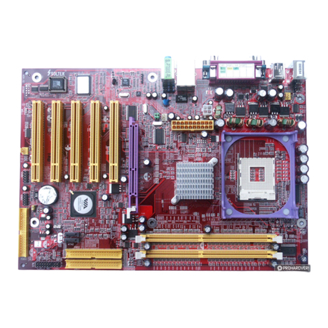
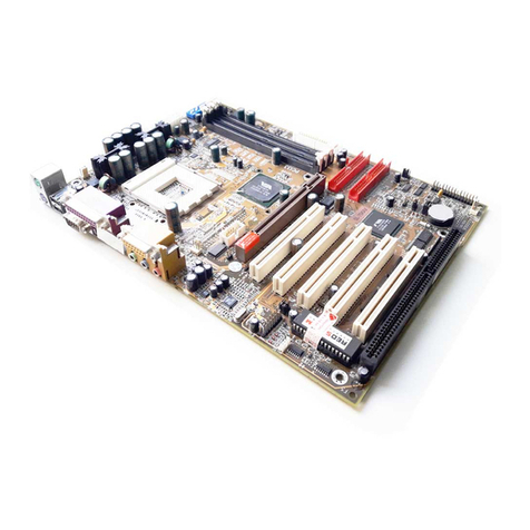
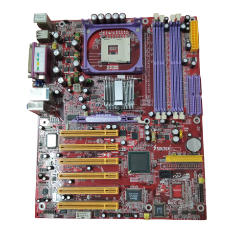
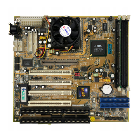
SOLTEK SL-75DRV-X User manual

R
The Soul Of Computer Technology
SL-75DRV/75DRV-X
USER MANUAL v1.4

NOTICE
Product Model : SL-75DRV/75DRV-X
Manual Revision : V1.4
Release Date : Au ust 2001
• AMD Athlon ThunderbirdTM, and DuronTM processors are trademarks of AMD Corporation.
• VIA, KT- 33, VT8363 and VT82C686A are trademarks of VIA Corporation.
• Norton AntiVirus, Norton Ghost are trademarks of Symantec Corporation.
T
his Users Guide & Technical Reference is to help system manu-
facturers and end-users set up and install the mainboard.
Every effort has been made to ensure that the information in this
manual is accurate. Soltek Computer Inc. is not responsible for print-
ing or clerical errors. Information in this document is subject to
change without notice and does not represent a commitment on the
part of Soltek Computer Inc.
No part of this manual may be reproduced, transmitted, translated
into any language in any form or by any means, electronic or
mechanical, including photocopying and recording, for any purpose
without the express written permission of Soltek Computer Inc.
Companies and products mentioned in this manual are for identifi-
cation purpose only. Product names appearing in this manual may
or may not be registered trademarks or copyrights of their respec-
tive companies.
Soltek Computer Inc. provides this manual “As is “ without warranty
of any kind, either express or implied, including but not limited to the
implied warranties or conditions of merchantability or fitness for a
particular purpose. In no event shall Soltek Computer Inc. be liable
for any loss or profits, loss of business, loss of use or data, interruption of
business, or for indirect, special, incidental, or consequential damages of
any kind, even if Soltek Computer Inc. has been advised of the possibility
of such damages arising from any defect or error in this manual or product.
Copyright © 2001 Soltek Computer Inc. All Rights Reser ed.

SOLTEK AROUND THE WORLD
SOLTEK COMPUTER INC.
Address : 7F, No. 306 3, Ta Tung Rd, Sec.1, Hsi Chih, Taipei
Hsien, Taiwan, R.O.C.
Telephone : 886 2 2642 9060
Fax : 886 2 2642 9065
Web site : http://www.soltek.com.tw
SOUL TECHNOLOGY EUROPE B.V.
Address : Hongkongstraat 55, 3047 BP Rotterdam. The Neth
erlands
Telephone : 31 10 2457492
Fax : 31 10 2457493
E mail : sales@soultech europe.com
Web site : http://www.soultech europe.com

75DRV/75DRV-X
4
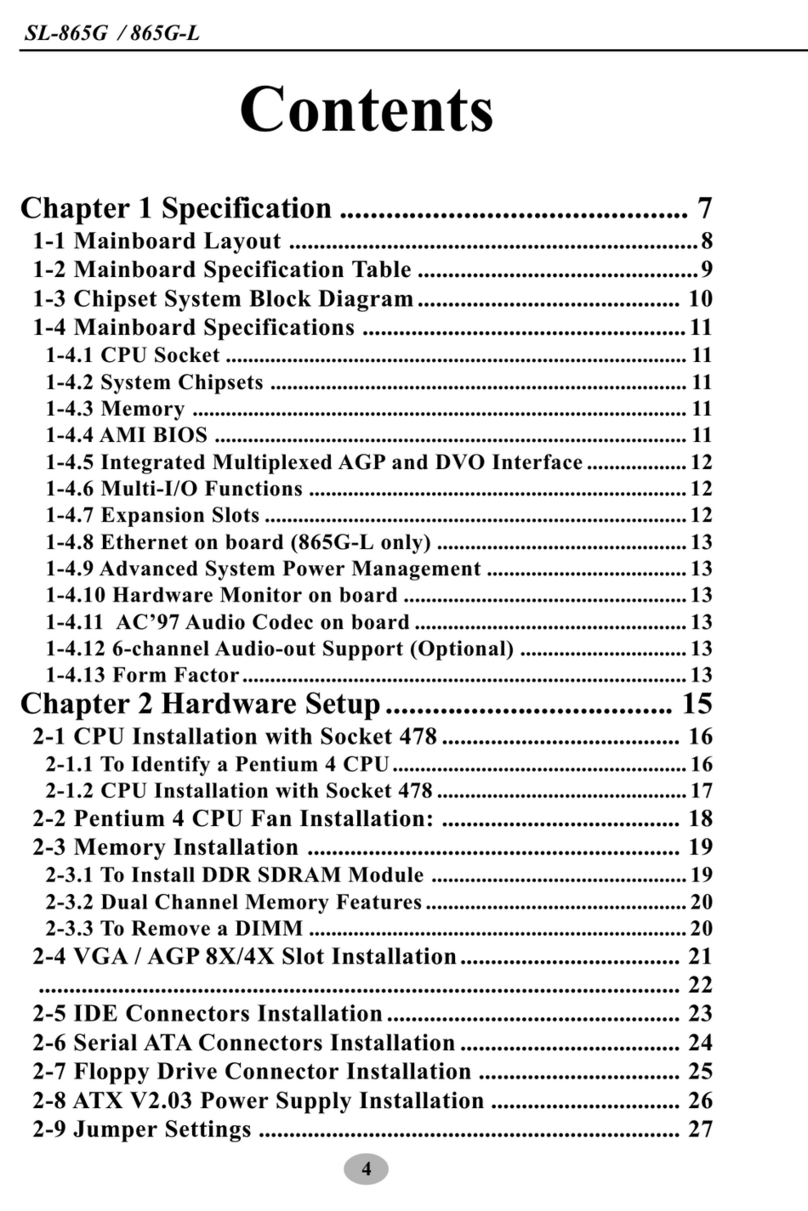
CONTENT
CHAPTER 1 INTRODUCTION ................................................. 9
1 1 MAINBOARD SPECIFICATION ............................................... 10
1 1.1 PROCESSOR ................................................................................. 10
1 1.2 CHIPSET......................................................................................... 10
1 1.3 AWARD BIOS V6.0 SUPPORTING................................................. 10
1 1.4 SOUND CONTROLLER.................................................................. 10
1 1.5 POWER MANAGEMENT ................................................................ 10
1 1.6 FULL FEATURED ACCELERATED GRAPHICS PORTS (AGP)
CONTROLLER ................................................................................ 11
1 1.7 MULTI I/O FUNCTION .................................................................... 11
1 1.8 EXPANSION SLOTS ....................................................................... 11
1 1.9 ADVANCED HIGH PERFORMANCE SDR/DDR DRAM
CONTROLLER ............................................................................... 11
1 1.10 FORM FACTOR ............................................................................ 12
1 1.11 HARDWARE MONITOR ................................................................ 12
1 1.12 OTHERS ....................................................................................... 12
1 2 MAINBOARD LAYOUT ............................................................ 13
1 2.1 Mainboard Layout 75DRV .......................................................... 13
1 2.2 Mainboard Layout 75DRV X ....................................................... 14
1 3 CHIPSET DIAGRAM 75DRV/75DRV X ............................... 15
CHAPTER 2 HARDWARE SETUP......................................... 17
2 1 CPU INSTALLATION ............................................................... 18
2 2 MEMORY INSTALLATION ....................................................... 19
2 3 ACCELERATED GRAPHICS PORT(AGP) PRO INSTALLATION ... 21

5
2 4 HDD/FDD INSTALLATION....................................................... 22
2 5 SWITCH SETTING FOR CPU FREQUENCY AND VOLTAGE 24
2 5.1 Information On AMD Socket 462 Processor (Model4, 5 Products) . 24
2 5.2 Information On AMD Socket 462 Processor (Model6, 7 Products) . 25
2 5.3 Frequency Ratio Select (By SW1 DIP1 DIP5) ................................ 26
2 5.4 Processor Core Voltage Select (By SW2 DIP1 DIP6)..................... 27
2 5.5 CPU External Frequency Setting (By SW3) .................................... 28
2 6 JUMPER SETTING FOR DEVICES ON BOARD .................... 29
2 6.1 JP1/JP2 Memory Module Voltage Select ........................................ 29
2 6.2 JP17 Power Lost Resume............................................................... 30
2 6.3 JP18/19 AGP Voltage Select ........................................................... 30
2 6.4 JBAT1 For Clear CMOS Data ......................................................... 31
2 7 CONNECTORS CONFIGURATIONS ...................................... 32
2 7.1 On Board FAN Connector (FAN1, FAN2, FAN3, FAN4) .................. 32
2 7.2 WOL1 Wake On LAN ...................................................................... 33
2 7.3 CD ROM Audio Connector (JCD_IN1) ............................................ 33
2 7.4 Thermal Sensor Connector (RT2) ................................................... 34
2 7.5 Complex Header CON1 .................................................................. 35
2 7.6 ATX Power Supply Connector ......................................................... 36
2 7.7 Chassis Panel Connector............................................................... 37
2 7.8 Smart Card Reader Connector (SCR1) .......................................... 38
2 7.9 Communication And Networking Riser Slot (CNR) ......................... 39
2 7.10 USB Header (USB2/USB3 Header) .............................................. 40
2 7.11 PS/2 Mouse And PS/2 Keyboard .................................................. 40
2 8 VOICE DIAGNOSTIC FUNCTION FOR 75DRV X ONLY....... 41
2 8.1 JP10 VD Tech II Language Select .................................................. 42

75DRV/75DRV-X
6
CHAPTER 3 SOFTWARE SETUP ......................................... 44
3 1 VIA CHIPSET DRIVER INSTALLATION (4 IN 1 DRIVER) ...... 45
3 2 HARDWARE MONITOR INSTALLATION ................................ 48
3 3 AC’97 AUDIO CODEC DRIVER INSTALLATION .................... 50
CHAPTER 4 BIOS SETUP ..................................................... 52
4 1 WHAT IS BIOS SETUP ............................................................ 53
4 2 HOW TO RUN BIOS SETUP ................................................... 53
4 3 WHAT IS CMOS ...................................................................... 53
4 4 WHAT IS POST ....................................................................... 53
4 5 BIOS UPGRADE ..................................................................... 53
4 5.1 BEFORE UPGRADING BIOS ......................................................... 54
4 5.2 UPGRADE PROCESS .................................................................... 54
4 6 BIOS SETUP CMOS SETUP UTILITY................................ 58
4 6.1 CMOS SETUP UTILITY .................................................................. 58
4 6.2 STANDARD CMOS SETUP ............................................................ 59
4 6.3 ADVANCED BIOS FEATURES ....................................................... 62
4 6.4 ADVANCED CHIPSET FEATURES ................................................ 66
4 6.5 INTEGRATED PERIPHERALS ....................................................... 71
4 6.6 POWER MANAGEMENT SETUP ................................................... 77
4 6.7 PNP / PCI CONFIGURATION ......................................................... 83
4 6.8 SMARTDOC ANTI BURN SHIELD ................................................. 86
4 6.9 FREQUENCY/VOLTAGE CONTROL.............................................. 88
4 6.10 LOAD OPTIMIZED DEFAULTS..................................................... 91
4 6.11 SET SUPERVISOR / USER PASSWORD .................................... 91
4 6.12 SAVE & EXIT SETUP.................................................................... 92
4 6.13 EXIT WITHOUT SAVING .............................................................. 92

7
APPENDICES ......................................................................... 94
APPENDIX 1 TECHNICAL TERMS .............................................. 95
APPENDIX 2 IDENTIFYING BIOS VERSION AND BIOS ............ 96
PART NUMBER ..................................................... 96
APPENDIX 3 IDENTIFYING MAINBOARD MODEL NUMBER .... 98

75DRV/75DRV-X
8
Mainboard
====Support CD
====User’s Manual
====Bundled Bonus Pack CD
====Bundled Bonus Pack Manual
====Temperature Sensor Cable
====ATA66/100 IDE Cable
====RS232 Cable
FDD Cable
ITEM LIST CHECKUP

Chapter 1 Introduction
9
CHAPTER 1
INTRODUCTION
This chap er con ains he following opics :
1-1 MAINBOARD SPECIFICATION
1-2 MAINBOARD LAYOUT
1-3 CHIPSET DIAGRAM
• This chapter briefly introduces the characteristics of the mainboards. It includes
the information regarding the chipset, CPU types, built in functions and layout.
Users will have more ideas about mainboards after reading this chapter.

75DRV/75DRV-X
10
1-1 MAINBOARD SPECIFICATION
1-1.1 PROCESSOR
• Supporting AMD Athlon Thunderbird processor up to 1.5GHz or above.
• Supporting AMD Athlon Duron processor up to 1.2GHz or above.
• Supporting 200MHz & 266MHz FSB bus.
• Supporting Processor VID(voltage ID) and FID(Frequency ID) auto
detection.
• Supporting Atholon 4 Processors.
1-1.2 CHIPSET
• North Bridge VIA VT8366 KT 266 AMD ATHLONTM NORTH BRIDGE.
• South Bridge VIA VT8233 VLINK CLIENT HIGHLY INTEGRATED SOUTH
BRIDGE.
• LPC I/O ITE 8705.
1-1.3 AWARD BIOS V6.0 SUPPORTING
• Plug & Play V1.0.
• Flash Memory for easy upgrade.
• Year 2000 compliant.
• BIOS writing protection.
• SmartDOC Anti Burn shield.
1-1.4 SOUND CONTROLLER
• SoundBlaster Pro Hardware and Direct Sound Ready AC97 Digital Audio
Controller with Codec onboard.
1-1.5 POWER MANAGEMENT
• ACPI 1.0 compliant (Advanced Configuration and Power Interface).
• APM V1.2 compliant (legacy power management).
• Supporting ACPI suspend STR mode (Suspend To DRAM) and POS mode
(Power On Suspend).
• System event monitoring with two event classes.
• Supporting PS/2 Keyboard & Mouse power on.
• Supporting Wake On LAN (WOL) & Wake On Modem.
• Supporting real time clock (RTC) with date alarm, month alarm, and century
field.
• USB boot up Function.

Chapter 1 Introduction
11
1-1.6 FULL FEATURED ACCELERATED GRAPHICS PORTS
(AGP) CONTROLLER
• AGP v2.0 compliant.
• Supports Side Band Addressing(SBA) mode (non multiplexed address /
data).
• Supporting 66MHz 1x, 2x, and 4x modes for AD and SBA signaling.
1-1.7 MULTI-I/O FUNCTION
• Two UltraDMA 33/66/100 Master Mode PCI EIDE ports.
• Two UARTs for complete Serial Ports.
• One dedicated IR connector:
At third serial port dedicated to IR function either through the two complete serial
ports or the third dedicated port Infrared IrDA (HPSIR) and ASK( Amplitude Shift
Keyed) IR.
• Multi mode parallel connector supporting:
Standard mode, ECP and EPP.
• Floppy Disk connector supporting:
One FDDs with drive swap function.
• Universal Serial Bus connector supporting:
USB v1.1 and Intel Universal HCI v1.1 compatible.
2 built in USB connectors, in addition to one internal USB header which requires
a USB cable to support 2 more optional USB ports.
• PS/2 keyboard connector.
• PS/2 Mouse connector.
1-1.8 EXPANSION SLOTS
• Five PCI bus Master slots.
• One CNR slot.
• One AGP PRO 4x mode slot.
• Three 184 pin DIMM slots.
• One SCR (Smart Card Reader) slot.
1-1.9 ADVANCED HIGH PERFORMANCE SDR/DDR DRAM
CONTROLLER
• Supporting memory size up to 3GB.
• Supporting 184 pin DDR SDRAM type only.
• Supporting PC1600 and PC2100 DDR SDRAM.

75DRV/75DRV-X
12
1-1.10 FORM FACTOR
• ATX form factor, 4 layer PCB.
• Mainboard size 22.0cm x 30.5cm.
1-1.11 HARDWARE MONITOR
• Programmable control, status to provide, monitoring and alarm for flexible
desktop management (software include).
• 5 positive voltage statuses monitoring.
• 2 temperatures statuses monitoring.
• 2 Fan speeds statuses monitoring.
1-1.12 OTHERS
• Supporting VD Tech II function (For 75DRV X only).

Chapter 1 Introduction
13
1-2 MAINBOARD LAYOUT
1-2.1 Mainboard Layou --- 75DRV
USB2
1
16
1
16
USB3
CNR 1
FLASH BIOS
USB0
USB1 PS/2
MOUSE
PS/2
K/B
LPT1
COM1COM2
GAME/MIDI PORT
MIC
SW1
ON
DIP
5 4 3 2 1
SW2
ON
DIP
6 5 4 3 2 1
CN1
ON DIP
1 2 3 4 5
SW3
FAN1
1 3
FAN3
1 3
CON1
SAPK RST PLED SLED
HDD/LED IR PWR SUSPEND
++
--
+-
16 30
1 15
RT2
SCR1
JBAT1
1 3
JP1
JP2
1 3
1 3
WOL1
1 3
4
1
JCD_IN1
1 3
JP17
PCI 1
PCI 2
PCI 3
PCI 4
PCI 5
SSF1
ZD1
DDR 266
AGP PRO 4X
FDC1
IDE1
IDE2
VIA
VT8233
AC'97
Codec
LPC I/O
Con roller
VIA
VT8366
Li
Ba ery
FAN2
1 3
Clock
Genera or
FAN4
1 3
LINE
OUT
LINE
IN
JP18
JP19
1 3
1 3
SOCKET A
RT1
Using non compliant memory with higher bus clock (over clocking) may
severely compromise the integrity of system.

75DRV/75DRV-X
14
USB2
1
16
1
16
USB3
CNR 1
FLASH BIOS
USB0
USB1
PS/2
MOUSE
PS/2
K/B
LPT1
COM1COM2
GAME/MIDI PORT
MIC
SW1
ON
DIP
5 4 3 2 1
SW2
ON
DIP
6 5 4 3 2 1
CN1
ON DIP
1 2 3 4 5
SW3
FAN1
1 3
FAN3
1 3
CON1
SAPK RST PLED SLED
HDD/LED IR PWR SUSPEND
++
--
+-
16 30
1 15 RT2
SCR1
JBAT1
1 3
JP1
JP2
1 3
1 3
WOL1
1 3
4
1JCD_IN1
1 3
JP17
PCI 1
PCI 2
PCI 3
PCI 4
PCI 5
SSF1
ZD1
DDR 266
AGP PRO 4X
FDC1
IDE1
IDE2
VIA
VT8233
AC'97
Codec
LPC I/O
Con roller
VIA
VT8366
Li
Ba ery
FAN2
1 3
Clock
Genera or
FAN4
1 3
LINE
OUT
LINE
IN
JP18
JP19
1 3
1 3
SOCKET A
RT1
VD-¤
TECH
JP10
1 3
1-2.2 Mainboard Layou --- 75DRV-X
Using non compliant memory with higher bus clock (over clocking) may
severely compromise the integrity of system.

Chapter 1 Introduction
15
1-3 CHIPSET DIAGRAM--- 75DRV/75DRV-X
• The VT8366 and VT8233 chipset is a high performance, cost effective and
energy efficient system controller for the implementation of AGP / PCI / ISA
desktop personal computer system based on 64 bit Socket A (AMD Athlon)
processors.
DDR Vlink
Host North
552 BGA
VT8233
Vlink
Client South
352 BGA
3D
Graphics
Controller
Athlon
Host CPU
SDR/VCM
& DDR
SDRAM
Clock
Buffer
Clock
Generator
SDR/DDR Memory Bus
AGP Bus
SYSCLK, SYSCLK#
INTR, NMI, SM#, STPCLK#,
IGNNE#, FERR#, A20M#,
PWROK, INIT#, RESET#
GCLK
PCLK
PCKRUN#
ATA33/66/100
MII/LAN
6x USB
LPC
SMBus
Power Plan & Peripheral Control
GPIO and ACPI Events
PCI Bus
CKE#
MCLK
HCLK
PCLK
CPUSTP#
PCISTP#
SUSCLK,
SUSST1#
GCKRUN#
Address
Out
CFWDRST
CONNECT
PROCRDY
In
Data
VT8366
Diagram of Apollo Pro266 System Block Using the VT8233 V Link
South Bridge

16
75DRV/75DRV-X
MEMO
MEM
O

17
Chapter 2 Hardware Setup
CHAPTER 2
HARDWARE SETUP
2-1 CPU INSTALLATION
2-2 MEMORY INSTALLATION
2-3 AGP PRO INSTALLATION
2-4 HDD/FDD INSTALLATION
2-5 SWITCH SETTING FOR CPU FREQUENCY AND
VOLTAGE
2-6 JUMPER SETTING FOR DEVICES ON BOARD
2-7 CONNECTORS CONFIGURATION
2-8 VOICE DIAGNOSTIC FUNCTION FOR 75DRV-X
ONLY
This chap er con ains he following opics :
ATTENTION !!!
1. Please refer o your processor ins alla ion or o her
documen a ion a ached o your CPU for de ailed in-
s alling ins ruc ion.
2. Ins alling a hea sink and cooling fan is necessary
for proper hea dissipa ion from your CPU. Incorrec
ins alla ion may resul in overhea ing and damage
of your CPU.
3. Before changing he se ing of CPU Vcore from BIOS
program, user SHOULD make sure of correc speci-
fica ion bo h of CPU CLOCK and RATIO. Incorrec
se ing may cause damage o your CPU.

18
75DRV/75DRV-X
WARNIN !!!
• Make sure that +5V DCV and +3.3 DCV capabilities of your power supply
are suitable for the processor.
• Any attempt to operate the AMD Athlon or Duron processor without a
suitable coolin Fan will dama e processor and other component.
2-1 CPU INSTALLATION
SOCKET 462
SOCKET 462
AMD
Take notice of the red circles
as shown below. While insert
ing the CPU into the socket,
you can find out there is a
definite pin orientation for
CPU and socket.
2
Pull out the lever from the
socket, and then raise the le
ver up to a 90 degree angle.
1
AMD
SOCKET 462
Make sure that the CPU is
placed into the socket tightly.
Then lower down the level to
complete the CPU installation.
3

19
Chapter 2 Hardware Setup
Ins alling DIMM
• Make sure you have the correct memory module type for your mainboard.
• Insert the module(s) as shown below, DIMMs have 184 pins and one notch
that will be matched by the onboard DIMM socket. Memory modules are
installed by inserting them straight into the slot until they “click” in the right
place. They only fit in one direction, so do not force them in by a wrong
direction.
184-Pin DIMM No ch Key Defini ions(2.5V)
DRAM Key Posi ion Vol age Key Posi ion
2.5V
2-2 MEMORY INSTALLATION
Removing DIMM
• Press down the holding clips on both sides of a DIMM socket and the
module will be released from it.
WARNING!!!
• Make sure to unplu your power supply before addin or removin memory
modules or other system components. Failure to do so may cause severe
dama e to both your mainboard and expansion cards.
• Be careful when insertin or removin DIMM. Forcin a DIMM in or out
of a socket improperly may dama e the memory module or the socket.
Some DIMMs which contain EDO or FTP DRAM are incompliant with
the mainboard. The M/B supports 2.5V true SDRAM DIMMs only.

20
75DRV/75DRV-X
USB2
1
16
1
16
USB3
CNR 1
FLASH BIOS
USB0
USB1
PS/2
MOUSE
PS/2
K/B
LPT1
COM1COM2
GAME/MIDI PORT
MIC
SW1
ON
DIP
5 4 3 2 1
SW2
ON
DIP
6 5 4 3 2 1
CN1
ON DIP
1 2 3 4 5
SW3
FAN1
1 3
FAN3
1 3
CON1
SAPK RST PLED SLED
HDD/LED IR PWR SUSPEND
++
--
+-
16 30
1 15
RT2
SCR1
JBAT1
1 3
JP1
JP2
1 3
1 3
WOL1
1 3
4
1
JCD_IN1
1 3
JP17
PCI 1
PCI 2
PCI 3
PCI 4
PCI 5
SSF1
ZD1
DDR 266
AGP PRO 4X
FDC1
IDE1
IDE2
VIA
VT8233
AC'97
Codec
LPC I/O
Con roller
VIA
VT8366
Li
Ba ery
FAN2
1 3
Clock
Genera or
FAN4
1 3
LINE
OUT
LINE
IN
JP18
JP19
1 3
1 3
SOCKET A
RT1
VD-¤
TECH
JP10
1 3
NOTICE : When LED
“ZD1” is on, meanin that
2.5V is operatin and
flowin into DIMM slots,
please do not add or remove
memory modules .
This manual suits for next models
1
Table of contents
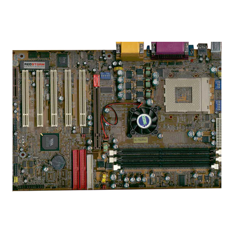
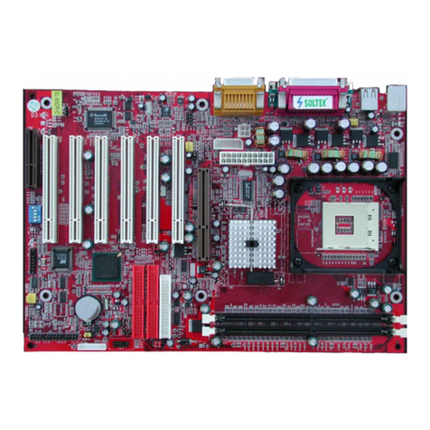
Other SOLTEK Motherboard manuals

SOLTEK
SOLTEK SL-65GS User manual

SOLTEK
SOLTEK SL-65EB User manual

SOLTEK
SOLTEK 85MR3 User manual

SOLTEK
SOLTEK SL-54A2 User manual

SOLTEK
SOLTEK 86SP3 User manual

SOLTEK
SOLTEK SL-65DRV User manual

SOLTEK
SOLTEK SL-55B5 User manual

SOLTEK
SOLTEK SL-52D2 User manual

SOLTEK
SOLTEK SL-63AV Use and care manual

SOLTEK
SOLTEK SL-KT880E-GR User manual

SOLTEK
SOLTEK SL-65FVB User manual

SOLTEK
SOLTEK SL-65LIV-T User manual

SOLTEK
SOLTEK 85DRV4-C User manual

SOLTEK
SOLTEK SL-65F+ User manual

SOLTEK
SOLTEK 865Pro-FGR User manual

SOLTEK
SOLTEK 85MR3-R User manual

SOLTEK
SOLTEK SL-85DIV User manual

SOLTEK
SOLTEK 85ERV User manual

SOLTEK
SOLTEK SL-55F5 User manual

SOLTEK
SOLTEK 65kv User manual