Sonel KT-640 User manual

USER MANUAL
THERMAL IMAGER
KT-640
SONEL S. A.
ul. Wokulskiego 11
58-100 Świdnica
version 1.1
09.09.2014

SONEL KT-640 THERMAL IMAGER
2
KT-640 Thermal Camera complies with current EU directives relating to electromagnetic compatibility
and safety.
Thank you for purchasing our thermal imager. KT-640 is a modern, easy and safe to use
measuring device. Please acquaint yourself with the present manual in order to avoid
measuring errors and prevent possible problems related to operation of the imager.
All products of Sonel S.A. are manufactured in accordance with Quality Management System which
is approved to ISO9001:2008 for the design, manufacturing and servicing.
Due the continuous development of our products, we reserve the right to introduce changes and im-
provements in the thermal imaging camera and in the software described in this manual without prior
notice.
Copyrights
© Sonel S.A., 2013. All rights reserved. This manual may not be copied, reproduced, translated or
transferred to any electronic carriers or in machine-readable form, in whole or in part, without the prior
written consent of Sonel S.A.

USER MANUAL
3
TABLE OF CONTENTS
1. 1. SAFETY................................................................................................................5
2. PREPARING THE CAMERA TO WORK. ..........................................................7
3. FUNCTION BUTTONS, JOYSTICK AND ON-SCREEN MENU......................7
3.1. BUTTONS LAYOUT...................................................................................................7
3.2. VIEWFINDER,TOUCH SCREEN,TV OUTPUT .............................................................8
3.3. ON-SCREEN INFORMATION ARRANGEMENT..............................................................9
3.4. MENU..................................................................................................................10
4. OPERATION INSTRUCTIONS AND THE CAMERA ADJUSTMENT.........10
4.1. TURNING THE CAMERA ON/OFF.............................................................................10
4.2. FOCUS ADJUSTMENT............................................................................................11
4.3. ENLARGING IMAGE –ZOOM (X2, X4, X8)...............................................................11
4.4. TEMPERATURE RANGE..........................................................................................11
4.4.1. High temperatures filter...............................................................................11
4.5. EMISSIVITY...........................................................................................................12
4.6. LED FLASHLIGHT ................................................................................................12
4.7. MANUAL CALIBRATION .........................................................................................13
4.8. SELECTING THE COLOUR PALETTE ........................................................................13
4.9. LASER POINTER....................................................................................................15
4.10. IMAGE MODES......................................................................................................15
5. CAPTURING AND SAVING IMAGES WITH VOICE ANNOTATION.........16
6. MEMORY BROWSNIG........................................................................................18
7. THERMAL IMAGE ANALYSIS .........................................................................20
7.1. SPOT ANALYSIS. ...................................................................................................20
7.2. LINE ANALYSIS.....................................................................................................21
7.3. AREA ANALYSIS....................................................................................................22
7.4. ISOTHERM ANALYSIS.............................................................................................23
8. FUNCTIONS AND PARAMETERS SETTINGS................................................23
8.1. THERMAL IMAGES ANALYSIS PARAMETERS.............................................................23
8.2. TARGET PARAMETERS (OBJECT)............................................................................24
8.3. SYSTEM SETTINGS. ...............................................................................................25
8.4. FUNCTION SETTINGS............................................................................................26
8.5. RESTORING TO DEFAULT SETTINGS. ......................................................................27
8.6. TOUCH PEN CALIBRATION ....................................................................................27
8.7. VIDEO RECORDING...............................................................................................28
8.8. WIFI....................................................................................................................28

SONEL KT-640 THERMAL IMAGER
4
8.9. HELP ..................................................................................................................31
8.10. INFORMATION ON HARDWARE AND FIRMWARE VERSION. .......................................31
8.11. FIRMWARE UPDATE .............................................................................................31
9. ACCURATE TEMPERATURE MEASUREMENT ..........................................32
10. POWER SUPPLY, CHARGING BATTERIES..................................................33
10.1. USING AC ADAPTER. ...........................................................................................33
10.2. BATTERY POWER SUPPLY......................................................................................33
10.2.1. Charging batteries ......................................................................................33
10.3. CHARGING BATTERY IN EXTERNAL BATTERY CHARGER...........................................34
10.4. GENERAL RULES OF USING LITHIUM BATTERIES....................................................35
11. CAMERA'S DRIVER AND SONEL THERMOANALYSE PC
INSTALLATION GUIDE.....................................................................................37
11.1. WINDOWS XP INSTALLATION GUIDE .....................................................................37
11.2. WINDOWS 7INSTALLATION GUIDE........................................................................42
11.3. WINDOWS 8INSTALLATION GUIDE........................................................................48
11.4. SONEL THERMOANALYZE INSTALLATION GUIDE ...................................................61
12. RECORDING INFRARED VIDEOS...................................................................62
12.1. RECORDING ON SD CARD. ...................................................................................62
12.2. RECORDING ON HARD DRIVE................................................................................62
12.3. „SONEL THERMOANALYZE®”SETUP ....................................................................63
12.4. RECORDING INFRARED VIDEO IN REAL TIME. ........................................................64
12.5. IR VIDEO MODE MENU.........................................................................................66
12.6. RECORD ANALYSIS DATA COMMAND....................................................................71
13. DATA TRANSMISSION ......................................................................................71
14. SPECIFICATIONS................................................................................................72
15. EXAMPLARY EMISSIVITY COEFFICIENT VALUES .................................75
16. CLEANING AND MAINTENANCE...................................................................76
17. CALIBRATION.....................................................................................................76
18. EQUIPMENT.........................................................................................................77
19. DISMANTLING AND DISPOSAL......................................................................78
20. MANUFACTURER...............................................................................................78

USER MANUAL
5
1.Safety
Before you proceed to operate the camera, acquaint yourself thoroughly with the present
manual and observe the safety regulations and specifications defined by the producer.
Any application that differs from those specified in the present manual may result
in a damage to the device and constitute a source of danger for the user.
The camera must not be used in rooms where special conditions are present e.g.
fire and explosion risk.
It is forbidden to use damaged or malfunctioning camera and is partially or fully
out of order.
In case the camera is not used for a long time, its batteries should be removed.
It is not allowed to use the camera with half-closed or opened battery cover and
do not use any other power adapter than the one supplied with the camera.
Repairs may be carried out only by an authorised service point.
KT-640 Thermal Imager is designed to measure and record the images in the infrared.
The camera is constructed in a manner which gives you maximum performance and safe-
ty at work, however the following precautions must be adhered to at all times (in addition
to any advised precautions applicable at the relevant work-site or work area):
Keep the camera steady during operation.
Do not use the camera in ambient temperatures exceeding its operation and
storage temperature ranges.
Do not direct the camera toward very high intensity radiation sources such
as the sun, lasers or welding arcs etc.
Do not expose the camera to dust and moisture. When operating the device near
water, ensure that it is adequately guarded against splashes
When the camera is not in use or is to be transported, ensure that the unit and
its accessories are stored in the protective carry case.
Do not jam the loudspeaker holes on the camera body.
Do not re-switch on the imager before 30 seconds after switching it off and do
not remove the battery while operating the instrument.
Do not throw, knock or shake intensely the camera and its components in order
to avoid the damage.
Do not attempt to open the imager body, as this action will void the warranty.
Keep the SD memory card for the exclusive use of the camera.
During operation, if the camera is to be moved from hot/cold place to cold/hot
place, e.g. from inside/outside to outside/inside of a room, switch the imager off and
leave it in the new workplace for 20 minutes, then turn it on and start normal
operation with an accurate temperature measurement. Sudden and rapid changes in
ambient temperature may cause fault temperature measurement and even damage
camera’s IR detector.

SONEL KT-640 THERMAL IMAGER
6
FPA setting (FPA -. Focal Plane Array): in order to ensure accurate temperature
measurement, the FPA detector was calibrated in different temperature points. After
switching the imager on, it performs auto calibration procedure (3 times during the
first minute). During the calibration, for about 2 seconde, the device does not
respond to user’s activity ( it is indicated by „calibration” word on screen).
Apart from that, autocalibration, of 2 seconds duration, performs automaticly
during operation of the device, and is dependent on external conditions and i salso
indicated by „calibration” word displayed on screen.
Calibration can be performed manually at any time. In order to do that you need
to go to real time mode screen by pressing C button (6) as many times until there is
only infrared image being displayed on screen with central point selected. Then you
need to press and hold C button for 2 seconds –calibration procedure will be per-
formed, and it will be indicated by „calibration” note on screen.
During imager operation its housing temperature increases and it’s a normal
phenomenon.
NOTE!
KT-160 Thermal camera has no parts that could
be repaired by its user. Never attempt
to dismantle or modify the camera. Opening the unit
invalidates the warranty.
NOTE!
Laser pointer installed in the camera may be
dangerous to eyes, in case of direct contact!
DO NOT DIRECTED THE LASER BEAM TOWARDS OTHER PERSONS OR
ANIMALS!
Please note that the laser beam may reflect off
shiny surfaces.
After turning the camera on, it performs internal test, during which, for few
seconds, laser pointer is being turned on as well. After turning the camera
on, until it reaches the point of being fully operational it is forbidden to aim it
at human and animals!!
NOTE!
Use only standard and additional accessories,
listed in "Equipment" section. Using other accessories does not ensure
proper operation of the camera and may cause its damage.

USER MANUAL
7
NOTE!
Due to the continuous development of the device, the design
of the display and its certain features may be slightly different than presented
in this manual.
2.Preparing the camera to work.
KT-640 can work with touch screen detached, however having it mounted significantly
simplifies its operation and features selection. When touch screen is detached, main
menu functions and analysis tools can be activated by pressing and moving Joystick.
Thermal image can be viewed through view finder (9). It is possible to activate laser point-
er, flashlight, real time image preview (buttons 18-20), using auto focus (button 21), man-
ual focus adjustment and zooming the image with Joystick (11).
In order to have both thermal and real time image projected on large screen (1) and to
have easy access to advanced functions, attach it by the grip to the socket on the upper
side of the camera. The grip should be slided into the socket from the front side till the end
in the manner that allows the proper connection of the LCD contact pins(25), and then se-
cure the grip using tightening gear (24 - by turning it right).
Touch pen slot (23) is located on the bottom part of the screen frame (1). Touch pen is
designed to work with the touch screen.
3.Function buttons, Joystick and on-screen menu
3.1. Buttons layout
Access to the camera's functions is provided through the buttons (16) located on the top
side of the housing ( , , ), buttons (18..21) located under the power off button and
through Joystick (11). Buttons layouts is presented at the inside cover page.
SONEL KT-640 THERMAL IMAGER
8
- button allowing to switch between temperature ranges displayed on screen and
from auto mode to manual mode.
- press this button to cancell currently selected function. Pressing C button several
times will result in returning to the previous sub menu (stepping back from different levels
of parameters and subfunction menus) until getting only visual image available on screen,
with no menus on. Press and hold button for 2 seconds, while having only thermal im-
age on screen, to perform calibration of the camera.
- freezes thermal image on screen. Press the button again to save the image into
the memory.
Joystick can be pressed like button and it can also be moved in both up-down and left-
right axis. Joystick operation depends on the currently running function.
3.2. Viewfinder, touch screen, TV output
During the camera operation in real time mode infrared image is displayed on both screen
(1) and viewfinder (thermal image refresh rate is 60 times per second).
After selecting proper functions by using buttons or touch screen, the following are being
displayed on screen: drop down menu bar, expanded analysis toolbar (its on-screen loca-
tion can be changed), status bar, temperature range bar and its corresponding color pal-
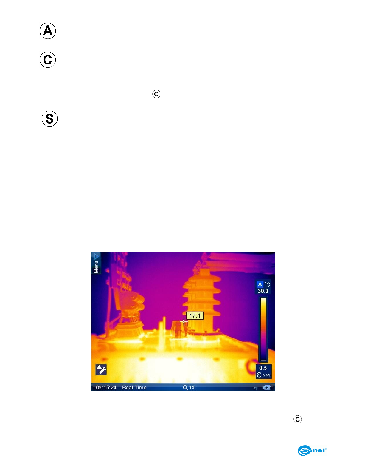
ette, and central point with its temperature value:
Additionally, above the bottom bar messages of each functions are being displayed (e.g.
"saving", "SD card removed").
Touch screen menu elements and temperature range bar hide after pressing button.
They show up again after freezing image on screen or after touching the screen.

USER MANUAL
9
Output signal from the camera can be simultaneously viewed at the same time on a TV
screen (monitor) by using RS232/Video cable (socket (13) on the camera) in PAL or
NTSC (depends on the video output settings selected in System Settings menu [section
8.3] ).
3.3. On-screen information arrangement
Bottom bar contains: real time clock; current mode status (real time image, frozen image
or memory browsing); zoom ratio; battery and power supply indicator; no SD card infor-
mation (visible only when SD card is missing).
SONEL KT-640 THERMAL IMAGER
10
An additional point indicating the location of the lowest or the highest temperature can be
put onto the screen. Activation and selection of this point can be made in the analysis pa-
rameters settings. (section 8.1).
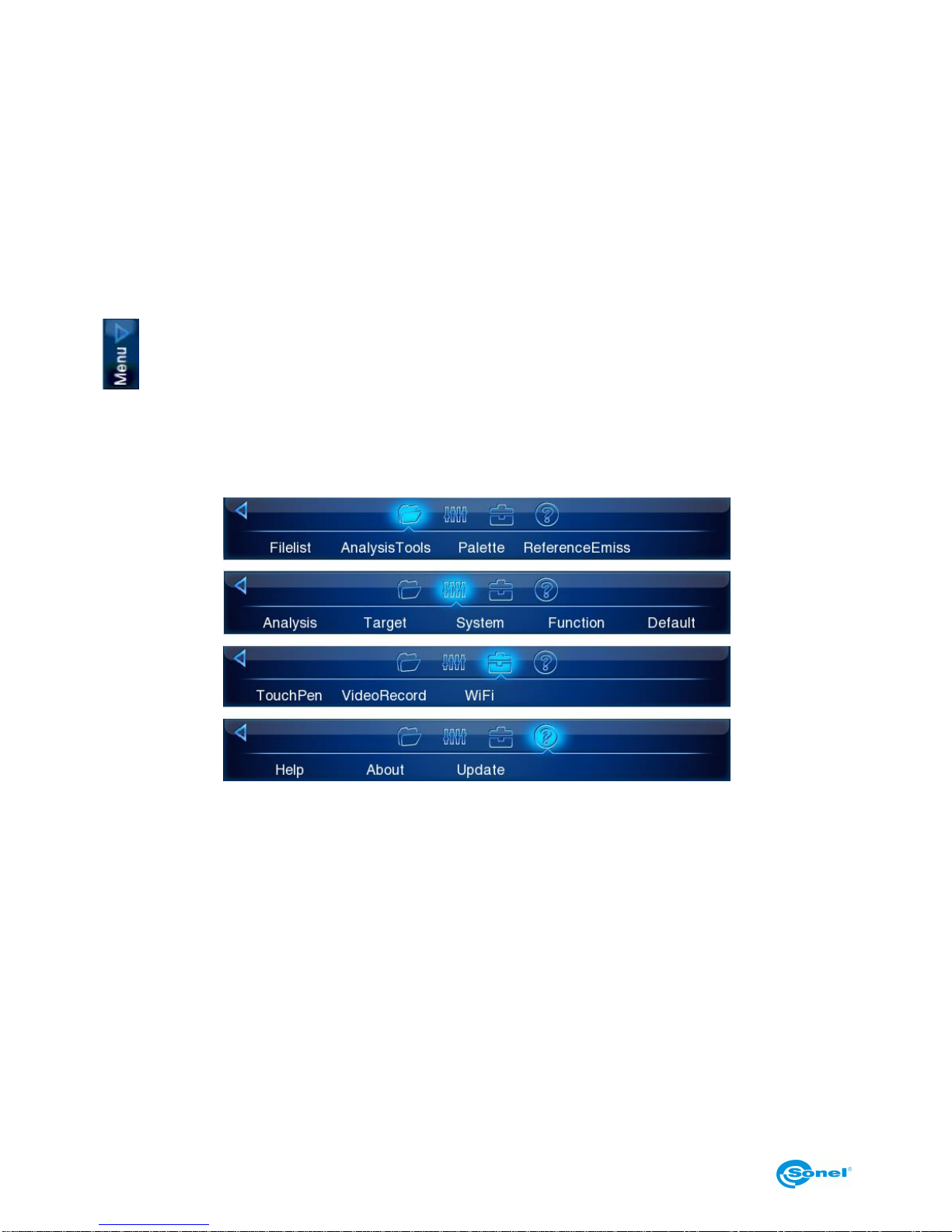
Functions put together in 4 groups can be selected upon expanding upper drop down
Menu. Analysis Tools options depend on whether the camera displays stored image, fro-
zen image or real time image.
3.4. Menu.
In real-time mode, when there is no icons on the screen, press the Joystick twice or touch
the touch screen once, and then repeat the same on the appearing
icon to make the drop down menu expand. It contains a list of functions, their settings
and parameters. Menu functions are grouped into 4 sections. Navigating through the
Menu is executed by using the Joystick or by the touch secreen.:
Individual functions available on the menu are described in subsequent sections of this
manual.
4.Operation Instructions And The Camera Adjustment
4.1. Turning the camera on/off
Press and hold the (7) button for around 2 seconds to turn the camera on. Splash screen
will apear on the display and then the camera will perform self-check test, after which the
camera is ready to use and goes into displaying real time infrared image.
In order to turn the camera off press and hold the "Power" button until the screen turns off.

USER MANUAL
11
4.2. Focus adjustment
Focus can be adjusted in manual or in auto mode. In manual mode aim the lens at the
target and then move the joystick up or down to zoom the focus point in or out. For very
precise focus setting it is recommended to use the "Zoom" function.
To adjust the focus automatically, use the (21) button. Press it and the camera will focus,
provided that the object, which the camera is being set to focus on, has a large thermal
contrast. In case the auto focus results are dissatisfying, use the manual focus mode.
4.3. Enlarging image –Zoom (x2, x4, x8)
Moving the Joystick right allows to magnify thermal image 2-, 4-, up to 8 times bigger,
while moving the Joystick left makes the image zoom out down to its nominal size.
Zooming can be also performed by pressing the field with the magnification symbol and its
ratio on it. It is located on the bottom bar on the screen (see section 3.3).
Image magnification allows accurate focusing. It should be remembered that KT-640 sup-
ports digital zoom only, so it is not advisable to save IR thermal images digitally enlarged..
4.4. Temperature range
Temperature range can be adjusted by buttons or by the use of touch screen when the
camera is in the real time mode, and when a real time infrared image is being displayed
on screen.
Press (6) button or click on icon or on the temperature value on icon on the
touch screen, to switch from automatic temperature mode into manual mode. This transi-
tion will be indicated by the "M" letter replacing "A" letter on the screen (see section 3.3)
and the temperature, that can now be adjusted manually, will be highlighted by the blue
line framing the field in which it is located. Now you can change the upper limit of the tem-
perature range by moving Joystick up/down or by sliding touch pen across the tempera-
ture bar. Whili changing the temperature, its value is marked by yellow background. To
change the lower range press (6) button again.
Press and hold (6) button for 2 seconds, or click "M" letter on icon with touch pen,
to go back into automatic temperature range selection mode.
4.4.1. High temperatures filter.
Full temperature range of KT-640 is -20°C do +800°C. It is divided into two filter ranges:
standard (filter 1 range: -20°C do +250°C) and high (filter 2 range: +200°C do +800°C).
When the temperature of the measured object exceeds selected filter range, instead of
temperature values, the camera will display following symbols on screen: "+++" or "---".
Those symbols indicate manual filter range adjustment.
To change the filter range go to real time image and press button for 3 seconds.

SONEL KT-640 THERMAL IMAGER
12
4.5. Emissivity.
To change the emmissivity coefficient value press and hold icon with touch pen (on
the value above εsign), and while keeping the pen pressed against the touch screen,
move it up (value will increase) or down (decrease).
εvalue can be also changed in "Target" menu in target parameters settings (described in
section 8.2):
Whilst clicking on emissivity coefficient symbol (ε) on , icon, or after selecting this
function from main menu:
the list of the most common materials with their emissivity coefficient values will be dis-
played.:
The right material can be selected by navigating across the list with Joystick and con-
firmed by pressing the Joystick button. Close the list by pressing ( )button. Selection can
also be made by using the touch pen. .
4.6. LED flashlight
In order to improve the work in dark locations KT-640 has been equipped with LED flash-

USER MANUAL
13
light. Turning it on is executed by pressing (18) button. Pressing the (18) button again will
increase the intensity of the flashlight brightness (3 levels) up to its maximum level. Press-
ing the (18) button further will repeat the sequence (turned off - level 1 - level 2 - level 3 -
turned off - ...etc.)
Information about the flashlight status and its current brightness level is displayed as an
icon in the low right corner of the screen. Enabling the flashlight and changing its bright-
ness can also be executed by clicking its icon on touch screen with pen.
This function is available when activated in the system settings menu (see section 8.3).
4.7. Manual calibration
During operation, the camera runs periodic auto-calibration procedure (it is signalled by
the closing shutter sound and the "Calibration" word appearing on the bottom of the
screen). Calibration can also be triggered manually at any time. while being in real time
mode (with infrared thermal image being displayed), press and hold button for 2 sec-
onds..
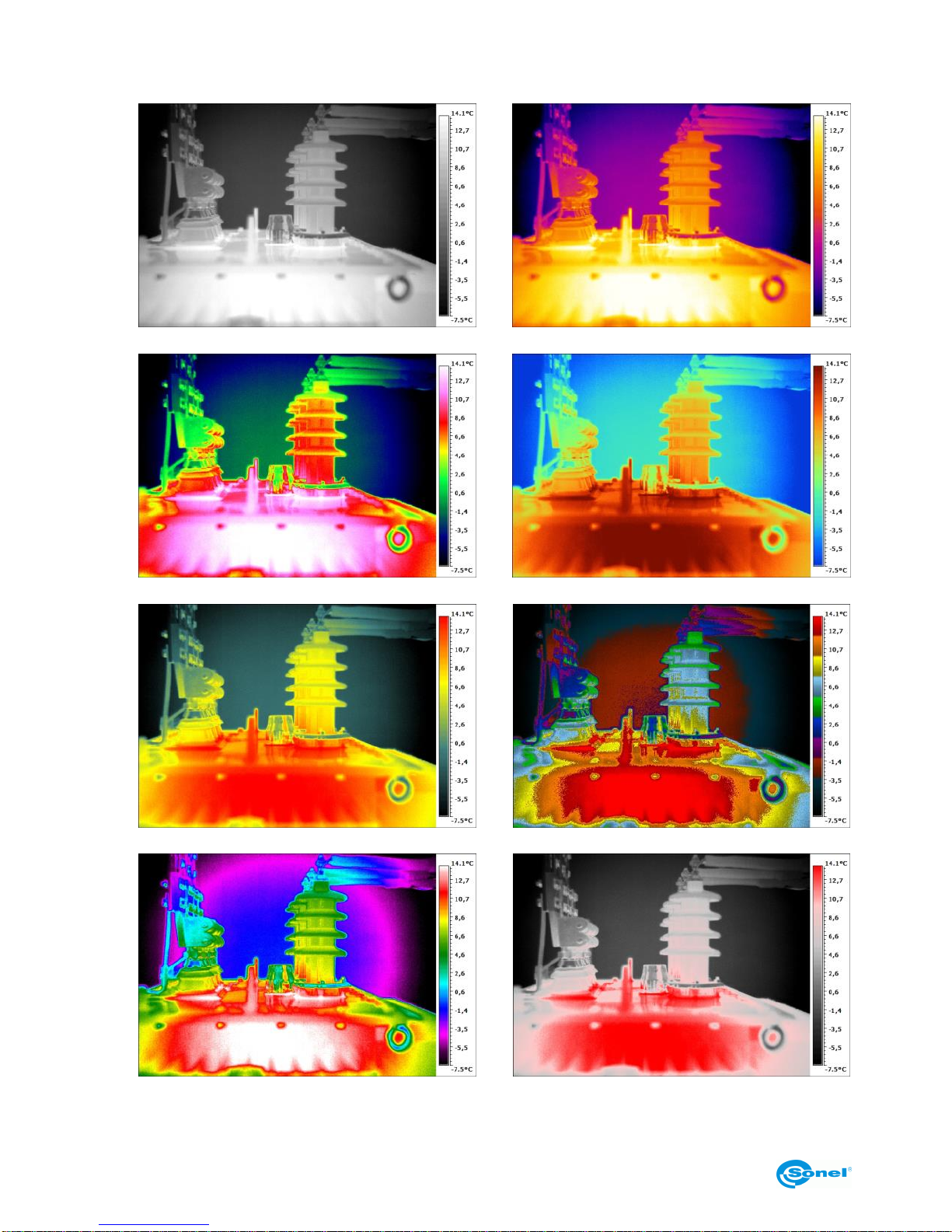
4.8. Selecting the colour palette
Color palette corresponding to the temperature values can be changed in every mode.
Select palette option in the Menu.:
or click on the temperature bar on screen and a window with the selection of 8 palettes
will pop up on.
Palette selection is made by clicking on chosen palette bar. After selecting desired palette
click once again on the temperature bar or press button (6). Palette no.2 is set by de-
fault.
SONEL KT-640 THERMAL IMAGER
14
Available colour palettes:
1
2
3
4
5
6
7
8

USER MANUAL
15
4.9. Laser pointer
Laser pointer can be activated, while being in real time mode, by pressing (20) button. Af-
ter activating or deactivating laser pointer, corresponding information is being displayed
on screen for 3 seconds.
NOTE!
Laser beam may damage eyes in case of direct contact! DO NOT LOOK INTO THE
LASER BEAM DIRECTLY AND DO NOT DIRECTED THE LASER BEAM TOWARDS
OTHER PERSONS OR ANIMALS! Special caution should be excercised as the la-
ser beam may reflect off shiny surfaces.
Due to safety reasons, Laser pointer is available after enabling it in function settings menu
(see "function settings", section 8.4).
4.10. Image modes
KT-640 captures both thermal and visual images. Thermal image mode can be switched
into visual image mode at any time while being in real time mode, or by freezing thermal
image on screen ( button), and also during browsing thermal images stored in the
memory.
Press (19) button to swith into visual image mode. Press the same button again to return
to thermal image mode.
Displayed image mode can also be changed using touch screen. In order to do that ex-
pand analysis tool bar and selec proper button on touch screen (depending on whether
the image is in real time mode or it's frozen one). Description of analysis tool is located in
section 7.
In case of frozen image or browsing thermal images stored in the memory, pressing
button will switch to visual image. Press to return to thermal image mode.
In real time image mode, press button to put thermal image on top of the visual one,
with possibility to adjust transparency (FUSION mode):

SONEL KT-640 THERMAL IMAGER
16
Infrared image transparency level and distance from the object can be adjusted using ver-
tical and horizontal sliders (using touch screen or Joystick). Selecting the lowest transpar-
ency value will result in only visual image being displayed. Pressing "IR" (or button) re-
sults in return to displaying full screen infrared image in real time mode.
It is advised to use FUSION mode for distances greater than 1,5m; In case of smaller dis-
tances significant displacement of both images can be observed (Parallax phenomenon).
5.Capturing and saving images with voice annotation
Caution. KT-640 utilizes external memory - SD card put inside the slot (15). If the SD card
is not inserted the camera will display infrared images in real time mode, and image can
also be freezed or being analysed, however it is not possible to store it in the memory.
The lack of SD card is indicated by the symbol displayed on status bar:
KT-640 displays image continuously, refreshing it 60 times per second. To capture an im-
age, press (6) button, which will freeze an image and will display menu elements on
screen. Information about the "freeze" mode is displayed on the bottom bar.
At this point:
- press button to save thermal image along with its corresponding visual image;
- click on temperature range icon (number defining upper range limit), or click on
icon (number defining lower range limit) to switch into manual adjustment of upper
and lower temperature range limits (see section 4.4). This operation allows to choose the
most optimal temperature ranges right after freezing an image on screen.

USER MANUAL
17
NOTE! Chosen limits values that are set for the captured images and will be used
for those images, but they will also remain set after returning to real time mode. Af-
ter saving an image switch to automatic temperature selection mode.
- click on emissivity coefficient symbol „ε” on icon to change its value for infrared im-
age by selecting it from the table of materials. Click on the value next to „ε” symbol to de-
fine its exact value by pressing touch pen on the value and moving pen up and down (in-
struction on how to change emissivity coefficient values is described in section 4.5 ).
NOTE! The value selected for the captured image will also remain active after re-
turning to real time mode. If you want to go back to the previous value you must se-
lect it again.
- click on icon or press Joystick button to expand analysis tool bar. Clicking on indi-
vidual icon allows to perform the analysis of the whole thermal image or its part
(detailed description in section 7);
- click on icon to view captured visual image;
- click on icon to open dialog box that allows to record voice note (up to 1 minute
lenght), which will be saved along with thermal image:

SONEL KT-640 THERMAL IMAGER
18
press to start recording (backward counting starts showing remaining time), press
to stop recording, and press to play recorded note. The record can be repeated,
and doing this will erase the previous one;
- press to mark image. On the file list (see section 6 "memory browsing") the image
will be marked with the flag icon placed in the upper left corner;
- press to save thermal image along with the optional voice note and mark. The
same result can be achieved by pressing , button.
Remarks:
1. Thermal image is saved in "extended jpeg format". Thanks to that it can be
viewed in all image browsers and graphics softwares (stored preview image will be
viewed in those cases). In addition to that all information related to the thermogram
is stored in one single extended jpeg file as well: temperature of each and every
pixel of thermal image, voice note and mark (flag symbol - described above).
2. editing thermal image in software other than Sonel ThermoAnalyse will result in
loosing all thermographic data.
3. If there is not enough space to save a file on SD card or when a saving error oc-
curs, proper information will be displayed on screen.
4. Saved thermal image file name is IRIxxxxx.jpg (where xxxxx are digits). Addition-
ally separate file with visual image is saved (as VISxxxxx.jpg, where xxxxx is the
same number as in its corresponding thermal image file name).
Both files must be placed in the same folder if visual image is to be used for analy-
sis in Sonel ThermoAnalyse program.
- click on icon to go to infrared video record mode (described in details in section
11).
6.Memory browsnig.
Go to Menu (see section 3.4) and click on the "Filelist" option to proceed into browsing
and editing images stored in the memory (on SD card).

USER MANUAL
19
Click on the thermal image thumbnail to open it in the mode allowing to view its corre-
sponding visual image, play voice note and perform analysis (click icon to open
analysis submenu).
Switch to infrared video file list to open videos stored on the memory card.
Click on the symbols located on the bottom bar to:
- go to the list of saved static thermal images;
- go to the list of saved infrared video files;
and - to toggle between screens with saved files (between those two symbols
number of screens available is shown along with the number of currently viewed screen);
- delete selected thermal image;
- delete all thermal images;
- return to real time mode.
Return to real time mode can also be executed by pressing (6) button.

SONEL KT-640 THERMAL IMAGER
20
7.Thermal image analysis
Thermal image analysis is possible for every image mode - real time, freezed and images
stored in memory.
Activate expanding AnalysisTools bar from main Menu::
or by pressing . icon. After expanding AnalysisTools bar following icons selection al-
low to perform:
- spot analysis (see below);
- line analysis (see below);
- area analysis (see below);
- isotherm analysis (see below);
- deleting of active area (object) of analysis.
Remaining icons, available on the bar depending on the image mode we're in, execute the
functions described in previous sections.
Press the triangle on the bottom of the bar to turn the bar back into icon.
7.1. Spot Analysis.
Press pen (or use Joystick) on button, available under expandable AnalysisTools
icon, to add spot on screen. The spot can be moved at any place on the screen with touch
pen. Up to 8 spots can be added on screen. Each point is accompanied by its tempera-
ture indication located in small field next to it.
Table of contents
Other Sonel Thermal Camera manuals


