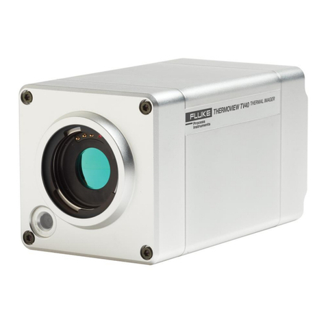
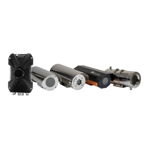
Fluke ThermoView TV30 Series User manual

ThermoView®TV30 Series
Thermal Imager Camera
Users Manual
5340877, English, Rev. 1.0, May 2023
© 2023 Fluke Process Instruments. All rights reserved. Printed in Germany. Specifications subject to change without notice.
All product names are trademarks of their respective companies.

Warranty
The manufacturer warrants this instrument to be free from defects in material and workmanship under normal use
and service for the periodof two years from date of purchase. This warranty extends onlyto the original purchaser.
This warranty shall not apply to fuses, batteries or any productwhich has beensubject to misuse, neglect, accident,
or abnormal conditions of operation.
In the event of failure of a product covered by this warranty, the manufacturer will repair the instrument when it is
returned by the purchaser, freight prepaid, to an authorized Service Facility within the applicable warranty period,
provided manufacturer’s examination discloses to its satisfactionthat the product was defective. The manufacturer
may, at its option, replace the product in lieu of repair. With regard to any covered product returned within the
applicable warranty period, repairs or replacement will be made without charge and with return freight paid by the
manufacturer, unless the failure was caused by misuse, neglect, accident, or abnormal conditions of operation or
storage, in which case repairs will be billed at a reasonable cost. In such a case, an estimate will be submitted
before work is started, if requested.
The foregoing warranty is in lieu of all other warranties, expressed or implied, including but not limited to any
implied warranty of merchantability, fitness, or adequacy for any particular purpose or use. Themanufacturer shall
not be liable for any special, incidental or consequential damages, whether in contract, tort, or otherwise.
Disclaimer for Export Control Classification
These products arecontrolled under ECCN6A003 and an export license isneededfor certain destinations. Please
see RS1 controls for licensing requirements.
This manual is available in different languages. In case of differences between the language versions, the
English manual is binding.

Table of Contents
Chapter Page
WARRANTY .......................................................................................................................................................2
TABLE OF CONTENTS..........................................................................................................................................3
LIST OF TABLES................................................................................................................................................. 6
LIST OF FIGURES................................................................................................................................................7
COMPLIANCE STATEMENT ...................................................................................................................................9
SAFETY INFORMATION....................................................................................................................................... 10
CONTACTS...................................................................................................................................................... 13
1 DESCRIPTION................................................................................................................................................ 14
1.1 Available Models.............................................................................................................................................................................................16
1.2 System Architecture........................................................................................................................................................................................17
2 TECHNICAL DATA .......................................................................................................................................... 18
2.1 Measurement Specification.............................................................................................................................................................................18
2.2 Optical Specifications......................................................................................................................................................................................19
2.2.1 Standard Lens........................................................................................................................................................................................19
2.2.2 Wide Angle Lens.................................................................................................................................................................................... 20
2.2.3 Tele Lens ...............................................................................................................................................................................................20
2.3 Electrical Specifications ..................................................................................................................................................................................21
2.4 Communications..............................................................................................................................................................................................22
2.5 Environmental Specifications.......................................................................................................................................................................... 22
2.6 Dimensions......................................................................................................................................................................................................23
2.7 Scope of Delivery............................................................................................................................................................................................23
3 BASICS ........................................................................................................................................................ 24
3.1 Measurement of Infrared Temperature...........................................................................................................................................................24
3.2 Emissivity of Target Object .............................................................................................................................................................................24
4 ENVIRONMENT............................................................................................................................................... 25
4.1 Ambient Temperature ..................................................................................................................................................................................... 25
4.2 Atmospheric Quality........................................................................................................................................................................................25
4.3 Protection ........................................................................................................................................................................................................25
4.4 Electrical Interference .....................................................................................................................................................................................25
5 INSTALLATION............................................................................................................................................... 26
5.1 Positioning.......................................................................................................................................................................................................26
5.2 Distance to Object...........................................................................................................................................................................................26
5.3 Focusing..........................................................................................................................................................................................................26
5.4 Mounting..........................................................................................................................................................................................................26

5.5 Powering..........................................................................................................................................................................................................27
5.5.1 Power over External Supply...................................................................................................................................................................27
5.5.2 Power over Ethernet...............................................................................................................................................................................28
5.6 Networking.......................................................................................................................................................................................................28
5.6.1 Ethernet Connector ................................................................................................................................................................................28
5.7 Connecting.......................................................................................................................................................................................................29
5.7.1 12-Pin Connector....................................................................................................................................................................................29
5.7.2 Digital Inputs...........................................................................................................................................................................................30
5.7.3 Digital Outputs........................................................................................................................................................................................30
6 OPERATION ..................................................................................................................................................32
6.1 Getting Started.................................................................................................................................................................................................32
6.2 LED Status Indicator........................................................................................................................................................................................32
6.3 Shutter .............................................................................................................................................................................................................33
7 WEB SERVER................................................................................................................................................34
7.1 Home Page......................................................................................................................................................................................................34
7.2 Camera Pages.................................................................................................................................................................................................35
7.2.1 <Camera> <Values> ..............................................................................................................................................................................35
7.2.2 <Camera> <Conditions>........................................................................................................................................................................38
7.2.3 <Camera> <Configuration>....................................................................................................................................................................41
7.3 Settings Pages.................................................................................................................................................................................................43
7.3.1 <Settings> <User Management> ...........................................................................................................................................................43
7.3.2 <Settings> <Networking>.......................................................................................................................................................................44
7.3.2.1 Obtain IP Address via DHCP / Auto IP ............................................................................................................................................45
7.3.2.2 Use a Static IP Address...................................................................................................................................................................45
7.3.2.3 HTTPS Security Certificate..............................................................................................................................................................45
7.3.3 <Settings> <Localization>......................................................................................................................................................................46
7.3.4 <Settings> <Device Management>........................................................................................................................................................47
7.4 I/O Pages.........................................................................................................................................................................................................48
7.4.1 <I/O> <Internal> .....................................................................................................................................................................................48
7.4.2 <I/O> <External> ....................................................................................................................................................................................49
7.4.3 <I/O> <MQTT> .......................................................................................................................................................................................51
7.4.4 <I/O> <OPC UA>....................................................................................................................................................................................53
8 ACCESSORIES...............................................................................................................................................56
8.1 Electrical Accessories......................................................................................................................................................................................56
8.1.1 Ethernet PoE Cable (A-CB-xx-M12-W08-xx).........................................................................................................................................57
8.1.2 12-Wire Cable, High Temp (A-CB-HT-M16-W12-xx).............................................................................................................................58
8.1.3 12-Wire Cable, Low Temp (A-CB-LT-M16-W12-xx)..............................................................................................................................60
8.1.4 Terminal Block (A-TV30-TB)..................................................................................................................................................................62
8.1.5 Ethernet Cable (A-CB-LT-RJ45-xx) .......................................................................................................................................................63
8.1.6 Fiber Optic Cable (A-CB-FO-xxx)..........................................................................................................................................................64
8.1.7 PoE Injector (A-TV-POE1) .....................................................................................................................................................................65

8.1.8 PoE Injector Industrial (A-TV-POE2).....................................................................................................................................................66
8.1.9 Power Supply DIN Rail (A-PS-DIN-24V) ...............................................................................................................................................67
8.1.10 Fiber Optic to Ethernet Converter (A-CON-FO-RJ45).........................................................................................................................68
8.1.11 Ethernet Switch (A-CON-SW)..............................................................................................................................................................69
8.1.12 I/O Modules..........................................................................................................................................................................................70
8.2 Mechanical Accessories..................................................................................................................................................................................71
8.2.1 Mounting Base (A-TV30-MB).................................................................................................................................................................72
8.2.2 Air Purge Collar (A-TV30-AP)................................................................................................................................................................74
8.2.3 Water Cooling Enclosure (A-TV30-AP-WC)..........................................................................................................................................76
8.2.3.1 Assembling ......................................................................................................................................................................................78
8.2.4 Outdoor Enclosure (A-TV-ENCVW).......................................................................................................................................................80
8.2.4.1 Specification.....................................................................................................................................................................................80
8.2.4.2 Installation........................................................................................................................................................................................81
8.2.5 Swivel Bracket (A-BR-S)........................................................................................................................................................................85
8.2.6 Protective Windows (S-TV30-PW).........................................................................................................................................................87
9 MAINTENANCE .............................................................................................................................................. 88
9.1 Fail-Safe Operation.........................................................................................................................................................................................88
9.2 Troubleshooting...............................................................................................................................................................................................89
9.3 Cleaning the Window ......................................................................................................................................................................................90
9.4 Re-Calibration .................................................................................................................................................................................................90
10 APPENDIX................................................................................................................................................... 91
10.1 Field of View Calculator ................................................................................................................................................................................ 91
10.2 Avoidance of Condensation.......................................................................................................................................................................... 92
10.3 Determination of Emissivity...........................................................................................................................................................................93
10.4 Typical Emissivity Values..............................................................................................................................................................................93

List of Tables
Table Page
Table 5-1: Pin Assignment for DIN Connector ............................................................................................................................................................30
Table 7-2: OPC UA Items ............................................................................................................................................................................................54
Table 8-3: Available Ethernet PoE Cables ..................................................................................................................................................................57
Table 8-4: Cable Specification.....................................................................................................................................................................................58
Table 8-5: Color Assignment to DIN Connector ..........................................................................................................................................................58
Table 8-6: Cable Specification.....................................................................................................................................................................................60
Table 8-7: Color Assignment to DIN Connector ..........................................................................................................................................................60
Table 8-8: Ethernet Cables – Available Lengths.........................................................................................................................................................63
Table 9-9: Troubleshooting..........................................................................................................................................................................................89
Table 10-10: Minimum device temperatures [°C/°F] ...................................................................................................................................................92

List of Figures
Figure Page
Figure 1-1: Front and Rear View of TV30 Infrared Cameras......................................................................................................................................15
Figure 1-2: Available Models.......................................................................................................................................................................................16
Figure 1-3: Principal System Architecture for TV30 SA Camera................................................................................................................................ 17
Figure 2-1: Dimensions of ThermoView TV30 ............................................................................................................................................................23
Figure 5-1: Field of View for the TV30 Camera...........................................................................................................................................................26
Figure 5-2: Principal Cabling of Power Supply and Ethernet......................................................................................................................................27
Figure 5-3: Principal Cabling of Power Supply and Ethernet......................................................................................................................................28
Figure 5-4: Connecting the Ethernet M12 Cable to the Camera ................................................................................................................................29
Figure 5-5: DIN Connector Pin Layout (pin side on camera)......................................................................................................................................29
Figure 5-6: Wiring the Digital Input (Example)............................................................................................................................................................30
Figure 5-7: Digital Output using Pull-Up......................................................................................................................................................................31
Figure 5-8: Digital Output using Open-Drain...............................................................................................................................................................31
Figure 6-1: LED Status Indicator.................................................................................................................................................................................32
Figure 7-1: Home.........................................................................................................................................................................................................34
Figure 7-2: Values .......................................................................................................................................................................................................35
Figure 7-3: Values Selection ....................................................................................................................................................................................... 36
Figure 7-4: Calculated Value.......................................................................................................................................................................................37
Figure 7-5: Conditions .................................................................................................................................................................................................38
Figure 7-6: Measurement Condition............................................................................................................................................................................39
Figure 7-7: Combination Condition..............................................................................................................................................................................40
Figure 7-8: Configuration.............................................................................................................................................................................................41
Figure 7-9: Shutter Settings ........................................................................................................................................................................................43
Figure 7-10: User Management ..................................................................................................................................................................................43
Figure 7-11: Networking ..............................................................................................................................................................................................44
Figure 7-12: Serial Number and Device Address .......................................................................................................................................................45
Figure 7-13: Networking ..............................................................................................................................................................................................46
Figure 7-14: Localization.............................................................................................................................................................................................46
Figure 7-15: Device Management............................................................................................................................................................................... 47
Figure 7-16: Internal I/O ..............................................................................................................................................................................................48
Figure 7-17: WAGO Module........................................................................................................................................................................................49
Figure 7-18: Principle of MQTT Network Protocol ......................................................................................................................................................51
Figure 7-19: MQTT......................................................................................................................................................................................................51
Figure 7-20: Principle of OPC UA Network.................................................................................................................................................................53
Figure 7-21: OPC UA ..................................................................................................................................................................................................53
Figure 8-1: Exemplary Ethernet PoE LT Cable...........................................................................................................................................................57
Figure 8-2: Pin Assignment (Front View)....................................................................................................................................................................57
Figure 8-3: 12-Wire Cable, High Temp Version..........................................................................................................................................................58
Figure 8-4: 12-Wire Cable, Low Temp Version...........................................................................................................................................................60
Figure 8-5: Terminal Block with Wire Color Assignment.............................................................................................................................................62
Figure 8-6: Ethernet Cable..........................................................................................................................................................................................63
Figure 8-7: PoE Injector for Office Environments .......................................................................................................................................................65
Figure 8-8: Industrial Power Supply............................................................................................................................................................................67
Figure 8-9: Mounting Base..........................................................................................................................................................................................72
Figure 8-10: Mounting Base Dimensions....................................................................................................................................................................72
Figure 8-11: Assembling the Mounting Base..............................................................................................................................................................73
Figure 8-12: Camera with Mounting Base...................................................................................................................................................................73
Figure 8-13: Air Purge Collar.......................................................................................................................................................................................74
Figure 8-14: Assembling the Air Purge Collar.............................................................................................................................................................74
Figure 8-15: Camera with Air Purge Collar and Mounting Base.................................................................................................................................75
Figure 8-16: Water Cooling Enclosure with Air Purge ................................................................................................................................................76
Figure 8-17: Enclosure Connections...........................................................................................................................................................................76

Figure 8-18: Enclosure Dimensions.............................................................................................................................................................................77
Figure 8-19: Outdoor Enclosure...................................................................................................................................................................................80
Figure 8-20: Dimensions..............................................................................................................................................................................................81
Figure 8-21: Swivel Bracket with Mount Beam............................................................................................................................................................85
Figure 8-22: Mounting Base to be fixed to the Mount Beam of Swivel Bracket..........................................................................................................85
Figure 8-23: Camera with Swivel Bracket....................................................................................................................................................................86
Figure 8-24: Protective Window...................................................................................................................................................................................87
Figure 10-1: Field of View Calculator for the Camera .................................................................................................................................................91

Compliance Statement
P
The device complies with the requirements of the European Directives:
EC – Directive 2014/30/EU – EMC
EC – Directive 2011/65/EU – RoHS Compliance
amended by Directive (EU) 2015/863
EC – Directive Nr. 1907/2006 – REACH
amended by Directive (EU) 2020/2096
EN 61326-1:2013 Electrical measurement, control and laboratory devices -
Electromagnetic susceptibility (EMC)
EN IEC 63000:2018 Technical documentation for the evaluation of electrical products with respect to
restriction of hazardous substances (RoHS)
Conforms to UK Conformity (UKCA).
ÃElectromagnetic Compatibility (KCC). Applies to use in Korea only. Class A Equipment
(Industrial Broadcasting & Communication Equipment)
This product meets requirements for industrial (Class A) electromagnetic wave
equipment and the seller or user should take notice of it. This equipment is intended for
use in business environments and is not to be used in homes.
Federal Communications Commission (FCC)
CFR 47, Part 15 Subpart B Class A

Safety Information
This document contains important information, which should be kept at all times with the instrument during its
operational life. Other users of this instrument should be given these instructions with the instrument. Eventual
updates tothis informationmust be addedto the original document. The instrument can only be operated by trained
personnel in accordance with these instructions and local safety regulations.
Acceptable Operation
This instrument is intended only for the measurement of temperature. Theinstrument is appropriate for continuous
use. The instrument operates reliably in demanding conditions, such as in high environmental temperatures, as
long as the documented technical specifications for all instrument components are adhered to. Compliance with
the operating instructions is necessary to ensure the expected results.
Unacceptable Operation
The instrument should not be used for medical diagnosis.
Replacement Parts and Accessories
Use onlyoriginal parts and accessories approved by the manufacturer. The use of other products can compromise
the operation safety and functionality of the instrument.
Exemplary Product Labeling

Safety Symbol
Description
»Consult user documentation.
WWarning. Risk of danger.
X
Warning. Hazardous voltage. Risk of electric shock.
JEarth (ground) terminal
.Protective conductor terminal
~
This product complies with the WEEE Directive marking requirements. The affixed label
indicates that you must not discard this electrical/electronic product in domestic
household waste. Product Category: With reference to the equipment types in the WEEE
Directive Annex I, this product is classed as category 9 "Monitoring and Control
Instrumentation" product. Do not dispose of this product as unsorted municipal waste.
°International Ingress Protection Marking
‡Conforms to China RoHS

XWWarning
To prevent possible electrical shock, fire, or personal injury and for safe operation of the Product:
Read all safety information before you use the Product.
Carefully read all instructions.
Do not alter the Product and use only as specified, or the protection supplied by the Product can be
compromised.
Do not use the Product if it operates incorrectly.
Do not use the Product if it is altered or damaged.
Do not put metal objects into connectors.
Use only specified replacement parts.
See emissivity information for actual temperatures. Reflective objects result in lower than actual
temperature measurements. These objects pose a burn hazard.
Have an approved technician repair the Product.
Do not use the Product around explosive gases, vapor, or in damp or wet environments.
Do not apply more than the rated voltage between the terminals or each terminal and earth ground.
Incorrect wiring can damage the Product and void the warranty. Before applying power, make sure all
connections are correct and secure!
To prevent possibleelectrical shock, fire, or personalinjury make sure thatthe Product isgrounded before
use.
The metallic enclosure of the Product is not necessarily earthed by installation. At least one of the
following safety measures must be met to minimize the danger of electrostatic charges:
oEarth grounding of the cable shield
oInstalling the Product’s metallic enclosure on an earth grounded mounting bracket or on any
other grounded bases
oProtect the operator from electrostatic discharge
WCaution
Storage and/or continual operation of the Imager in extreme ambient temperature conditions can result
in temporary interruptionof operation. If this occurs, let the Imager stabilize (cool down or warm up) before
you resume operation.

Contacts
Fluke Process Instruments
America
Everett, WA USA
Tel: +1 800 227 8074 (USA and Canada, only)
+1 425 446 6300
solutions@flukeprocessinstruments.com
EMEA
Berlin, Germany
Tel: +49 30 478 0080
info@flukeprocessinstruments.de
China
Beijing, China
Tel: +86 10 6438 4691
info@flukeprocessinstruments.cn
Technical Support
USA & Canada +1 425 446 6300
Europe +49 30478008444
Latin America +1 831 458 3900
Australia & New Zealand +1 831 458 3900
Asia
Singapure +65 67995578
Japan +81 3 6714 3114
India +65 67995578
China +86 1064384691
techsupport@flukeprocessinstruments.com
www.flukeprocessinstruments.com

ThermoView®TV30 Series
Users Manual, Rev. 1.0, May 2023
14
1 Description
The TV30 cameras define a new class of high-performance multi-product thermal imager, providing the models
with a full complement of accessories with an IP67 environmental rating that can operate in the harshest
environments.
For industrial applications requiring a standalone sensor, the rugged TV30 SA models offer advanced on-board
analytics capabilities including integrated and scalable I/O. The integrated I/O is standard with every SA camera
and provides a simple, easy to install solution for factory automation and processapplications. For added flexibility,
the imager can interface directly to external I/O modules for more demanding applications. For even simpler and
more direct communications with factory automation systems, the TV30 SA models offer fieldbus flexibility
including OPC UA and MQTT communications.
Key features and benefits:
Wide temperature range: -10 to 1300°C (14 to 2372°F)
320 x 240 and 640 x 480 infrared resolution
9 or 60 Hz models available
Rugged housing, IP67 rated
Remote motorized focus
Multiple lens options available
Stand-alone camera with on-board analytics including alarms, conditionmonitoring, and AOI calculations
LAN/Ethernet with PoE for communication provides access to Web Server
High ambient temperatures with cooling enclosure
Full complement of accessories including air purge and outdoor enclosure

Description
Available Models
15
1
Figure 1-1: Front and Rear View of TV30 Infrared Cameras
Protective Window
(replacable)
Status
LED
1 Gbit/s Ethernet PoE
M12 connector, 8 pin DIN M16 Connector,
12 pin

ThermoView®TV30 Series
Users Manual, Rev. 1.0, May 2023
16
1.1 Available Models
The following TV30 model variants are available.
Figure 1-2: Available Models
Model Temp Range IR Resolution Lens Interface Remark
TV33 SA -10 to 1300°C
(14 to 2372°F) 320 x 240 30° x 22° (Standard)
48° x 36° (Wide)
22° x 16° (Tele)
MQTT
OPC UA
I/O Modules
operates as stand-alone device
built-in http web server for real
time view and configuration
TV36 SA -10 to 1300°C
(14 to 2372°F) 640 x 480 30° x 22° (Standard)
48° x 36° (Wide)
22° x 16° (Tele)
MQTT
OPC UA
I/O Modules
operates as stand-alone device
built-in http web server for real
time view and configuration
TV3
X
–
XX
–
X
–
X
–
XX
| | | | | |
Series Model Type Temp Range Lens Frame Rate
3- 320x240 pixel SA - stand alone L S - Standard 60 - 60 Hz
6- 640x480 pixel -10 to 1300°C W- Wide 09 - 9 Hz
(14 to 2372°F) T- Tele
Example: TV33–SA–L–S–60

Description
System Architecture
17
1
1.2 System Architecture
Figure 1-3: Principal System Architecture for TV30 SA Camera
TV30 SA Camera External I/O
Internal I/O
Processing Unit (PLC)
OPC UA
MQTT SCADA/HMI

ThermoView®TV30 Series
Users Manual, Rev. 1.0, May 2023
18
2 Technical Data
2.1 Measurement Specification
Temperature Range -10 to 1300°C (14 to 2372°F)
indication starting at -20°C (-4°F)
Sub range 1: -10 to 100°C (14 to 212°F)
Sub range 2: 20 to 250°C (68 to 482°F)
Sub range 3: 200 to 1300°C (392 to 2372°F)
Auto-range scaling for TV30 SA models
Spectral Response 8 to 14 µm
Detector uncooled focal plane array (micro bolometer)
Resolution
TVx3 320 x 240 pixels (76,800 pixels), 24 µm pitch
TVx6 640 x 480 pixels (307,200 pixels), 12 µm pitch
Frame Rate
TV30 SA 9 Hz – for internal acquisition and processing, 9 Hz refresh rate for web server
or
60 Hz – for internal acquisition and processing, 15 Hz refresh rate for web server
Thermal Time Constant112 ms
Accuracy2± 2°C (4°F) or ± 2% of reading (whichever is greater)
Note
To maintainthe accuracy specification, it is recommended that the instrument be calibrated annually.
Temperature Coefficient 0.2°C / K or 0.2% / K (whichever is greater)
to be added on top of accuracy specification for every 1 K ambient temperature
delta from 25°C (73°F)
Thermal Sensitivity3(NETD)
all models 120 mK (60 Hz), 80 mK (30 Hz, frame averaging, theoretical)
Emissivity Correction 0.10 to 1.00
1at 63%
2at ambient temperature 25°C (77°F), emissivity = 1.0 and calibration geometry
3at internal temperature 25°C (77°F) and sub range 1, emissivity = 1.0 and calibration geometry

Technical Data
Optical Specifications
19
2
2.2 Optical Specifications
The following optical specification is based onthe theoretical calculated spot size derived on the pitch of the camera
detector array and the lens focal length. The Instantaneous Field of View (IFOV) specifies the size of the image of
an individual detector element in the object plane assuming ideal imaging optics. Typically, for accurate
temperature measurements, the target area needs to be larger than that determined by the calculated theoretical
IFOV. That target area is stated bythe Measurement Field of View (MFOV), which corresponds to anarea of 3 x 3
pixels.
2.2.1 Standard Lens
Field of View (FOV) 30° x 22° (horizontal x vertical)
Focus Range 220 mm to ∞(8.7 in to ∞)
TV33
IFOV 1.6 mrad
MFOV 4.9 mrad
TV36
IFOV 0.8 mrad
MFOV 2.5 mrad
Table 2-1: Exemplary Values for Standard Lens
Measuring distance Thermal image (H x V) Model IFOV (1 pixel) MFOV (3 x 3 pixel)
0.22 m (0.72 ft) 0.118 x 0.086 m (0.4 x 0.3 ft) TV33 0.4 mm (14.2 mil) 1.1 mm (42.5 mil)
TV36 0.2 mm (7.1 mil) 0.5 mm (21.3 mil)
0.5 m (1.6 ft) 0.268 x 0.194 m (0.9 x 0.6 ft) TV33 0.8 mm (31.4 mil) 2.5 mm (94.3 mil)
TV36 0.4 mm (15.7 mil) 1.2 mm (47.1 mil)
1.0 m (3.2 ft) 0.536 x 0.389 m (1.7 x 1.2 ft) TV33 1.6 mm (62.8 mil) 4.9 mm (188.5 mil)
TV36 0.8 mm (31.4 mil) 2.5 mm (94.3 mil)
5.0 m (16 ft) 2.679 x 1.944 m (8.6 x 6.2 ft) TV33 8.2 mm (373.2 mil) 24.5 mm (1119.5 mil)
TV36 4.1 mm (157.1 mil) 12.3 mm (471.4 mil)
10 m (33 ft) 5.359 x 3.888 m (17.7 x 12.8 ft) TV33 16.4 mm (648.1 mil) 49.1 mm (1944.4 mil)
TV36 8.2 mm (324.1 mil) 24.5 mm (972.2 mil)

ThermoView®TV30 Series
Users Manual, Rev. 1.0, May 2023
20
2.2.2 Wide Angle Lens
Field of View (FOV) 48° x 36° (horizontal x vertical)
Focus Range 100 mm to ∞(3.9 in to ∞)
TV33
IFOV 2.6 mrad
MFOV 7.9 mrad
TV36
IFOV 1.3 mrad
MFOV 3.9 mrad
Table 2-2: Exemplary Values for Wide Angle Lens
Measuring distance Thermal image (H x V) Model IFOV (1 pixel) MFOV (3 x 3 pixel)
0.1 m (0.33 ft) 0.089 x 0.065 m (0.3 x 0.2 ft) TV33 0.3 mm (10.3 mil) 0.8 mm (31 mil)
TV36 0.1 mm (5.2 mil) 0.4 mm (15.6 mil)
0.5 m (1.6 ft) 0.445 x 0.325 m (1.4 x 1 ft) TV33 1.3 mm (50.3 mil) 3.9 mm (150.8 mil)
TV36 0.7 mm (25.1 mil) 2 mm (75.4 mil)
1.0 m (3.2 ft) 0.890 x 0.650 m (2.8 x 2.1 ft) TV33 2.6 mm (100.6 mil) 7.9 mm (301.7 mil)
TV36 1.3 mm (50.3 mil) 3.9 mm (150.8 mil)
5.0 m (16 ft) 4.452 x 3.249 m (14.2 x 10.4 ft) TV33 13.1 mm (508.8 mil) 39.3 mm (1508.3 mil)
TV36 6.5 mm (251.4 mil) 19.6 mm (754.2 mil)
10 m (33 ft) 8.905 x 6.498 m (29.4 x 21.4 ft) TV33 26.2 mm (1037 mil) 78.5 mm (3111 mil)
TV36 13.1 mm (518.5 mil) 39.3 mm (1555.5 mil)
2.2.3 Tele Lens
Field of View (FOV) 22° x 16° (horizontal x vertical)
Focus Range 190 mm to ∞(7.5 in to ∞)
TV33
IFOV 1.2 mrad
MFOV 3.6 mrad
TV36
IFOV 0.6 mrad
MFOV 1.8 mrad
Table 2-3: Exemplary Values for Tele Lens
Measuring distance Thermal image (H x V) Model IFOV (1 pixel) MFOV (3 x 3 pixel)
0.19 m (0.63 ft) 0.074 x 0.053 m (0.2 x 0.2 ft) TV33 0.2 mm (9.1 mil) 0.7 mm (27.2 mil)
TV36 0.1 mm (4.5 mil) 0.3 mm (13.6 mil)
0.5 m (1.6 ft) 0.194 x 0.141 m (0.6 x 0.4 ft) TV33 0.6 mm (23 mil) 1.8 mm (69.1 mil)
TV36 0.3 mm (11.5 mil) 0.9 mm (34.6 mil)
1.0 m (3.2 ft) 0.389 x 0.281 m (1.2 x 0.9 ft) TV33 1.2 mm (46.1 mil) 3.6 mm (138.3 mil)
TV36 0.6 mm (23 mil) 1.8 mm (69.1 mil)
5.0 m (16 ft) 1.944 x 1.405 m (6.2 x 4.5 ft) TV33 6 mm (230.4 mil) 18 mm (691.3 mil)
TV36 3 mm (115.2 mil) 9 mm (345.7 mil)
10 m (33 ft) 3.888 x 2.811 m (12.8 x 9.3 ft) TV33 12 mm (475.3 mil) 36 mm (1425.9 mil)
TV36 6 mm (237.6 mil) 18 mm (712.9 mil)
Table of contents
Other Fluke Thermal Camera manuals

Fluke
Fluke TiS10 Original instructions

Fluke
Fluke Ti105 User manual

Fluke
Fluke FlexCam Ti40 User manual

Fluke
Fluke tix640 User manual

Fluke
Fluke TiS55+ User manual

Fluke
Fluke Ti40FT-20 User manual

Fluke
Fluke Ti20 User manual

Fluke
Fluke ThermoView TV43 User manual

Fluke
Fluke Ti32 Instruction manual

Fluke
Fluke tix640 User manual