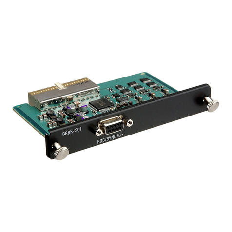
Sony BKMW-E2000 User manual

OPERATION MANUAL [English]
1st Edition
NETWORK INTERFACE BOARD
BKMW-E2000

For the customers in the USA
This equipment has been tested and found to comply with
the limits for a Class A digital device, pursuant to Part 15 of
the FCC Rules. These limits are designed to provide
reasonable protection against harmful interference when the
equipment is operated in a commercial environment. This
equipment generates, uses, and can radiate radio frequency
energy and, if not installed and used in accordance with the
instruction manual, may cause harmful interference to radio
communications. Operation of this equipment in a residential
area is likely to cause harmful interference in which case the
user will be required to correct the interference at his own
expense.
You are cautioned that any changes or modifications not
expressly approved in this manual could void your authority
to operate this equipment.
The shielded interface cable recommended in this manual
must be used with this equipment in order to comply with the
limits for a digital device pursuant to Subpart B of Part 15 of
FCC Rules.
This device complies with Part 15 of the FCC Rules.
Operation is subject to the following two conditions: (1) this
device may not cause harmful interference, and (2) this
device must accept any interference received, inmcluding
interference that may cause undesired operation.
For customers in Canada
This Class A digital apparatus complies with Canadian ICES-
003.
Pour les utilisateurs au Canada
Cet appareil numérique de la classe A est conforme à la
norme NMB-003 du Canada.
For the customers in Europe
This product with the CE marking complies with both the
EMC Directive (89/336/EEC) and the Low Voltage Directive
(73/23/EEC) issued by the Commission of the European
Community.
Compliance with these directives implies conformity to the
following European standards:
• EN60065: Product Safety
• EN55103-1: Electromagnetic Interference (Emission)
• EN55103-2: Electromagnetic Susceptibility (Immunity)
This product is intended for use in the following
Electromagnetic Environment(s):
E1 (residential), E2 (commercial and light industrial), E3
(urban outdoors) and E4 (controlled EMC environment, ex.
TV studio).
Pour les clients européens
Ce produit portant la marque CE est conforme à la fois à la
Directive sur la compatibilité électromagnétique (EMC) (89/
336/CEE) et à la Directive sur les basses tensions (73/23/
CEE) émises par la Commission de la Communauté
européenne.
La conformité à ces directives implique la conformité aux
normes européennes suivantes:
• EN60065: Sécurité des produits
• EN55103-1: Interférences électromagnétiques (émission)
• EN55103-2: Sensibilité électromagnétique (immunité)
Ce produit est prévu pour être utilisé dans les
environnements électromagnétiques suivants:
E1 (résidentiel), E2 (commercial et industrie légère), E3
(urbain extérieur) et E4 (environnement EMC contrôlé ex.
studio de télévision).
Für Kunden in Europa
Dieses Produkt besitzt die CE-Kennzeichnung und erfüllt
sowohl die EMV-Direktive (89/336/EEC) als auch die
Direktive Niederspannung (73/23/EEC) der EG-Kommission.
Die Erfüllung dieser Direktiven bedeutet Konformität für die
folgenden Europäischen Normen:
• EN60065: Produktsicherheit
• EN55103-1: Elektromagnetische Interferenz (Emission)
• EN55103-2: Elektromagnetische Empfindlichkeit
(Immunität)
Dieses Produkt ist für den Einsatz unter folgenden
elektromagnetischen Bedingungen ausgelegt:
E1 (Wohnbereich), E2 (kommerzieller und in beschränktem
Maße industrieller Bereich), E3 (Stadtbereich im Freien) und
E4 (kontrollierter EMV-Bereich, z.B. Fernsehstudio).
Notice
© 2002 Sony Corporation. All rights reserved. This manual or
the software described herein, in whole or in part, may not be
reproduced, translated or reduced to any machine readable
form without prior written approval from Sony Corporation.
SONY CORPORATION PROVIDES NO WARRANTY WITH
REGARD TO THIS MANUAL, THE SOFTWARE OR OTHER
INFORMATION CONTAINED HEREIN AND HEREBY
EXPRESSLY DISCLAIMS ANY IMPLIED WARRANTIES OF
MERCHANTABILITY OR FITNESS FOR ANY PARTICULAR
PURPOSE WITH REGARD TO THIS MANUAL, THE
SOFTWARE OR SUCH OTHER INFORMATION. IN NO
EVENT SHALL SONY CORPORATION BE LIABLE FOR
ANY INCIDENTAL, CONSEQUENTIAL OR SPECIAL
DAMAGES, WHETHER BASED ON TORT, CONTRACT,
OR OTHERWISE, ARISING OUT OF OR IN CONNECTION
WITH THIS MANUAL, THE SOFTWARE OR OTHER
INFORMATION CONTAINED HEREIN OR THE USE
THEREOF.
Sony Corporation reserves the right to make any
modification to this manual or the information contained
herein at any time without notice.
The software described herein may also be governed by the
terms of a separate user license agreement.
Trademarks
The brands and product names are in most cases
trademarks of their respective owners, and are used to
represent their products or services.
1
Overview.....................................................................................................3
E-VTR Functions .................................................................................3
E-VTR Manager Application Software Functions...............................3
System Configuration...........................................................................3
Preparations ...............................................................................................7
For Using a Computer ..........................................................................7
Basic Network Settings ........................................................................7
Starting E-VTR Manager .........................................................................7
E-VTR Manager window menus..........................................................7
E-VTR Manager Window Tool Buttons ..............................................9
Registering E-VTRs...................................................................................9
Accessing E-VTRs From the Computer.............................................10
VTR Window Configuration ..................................................................12
Creating Files ...........................................................................................14
Creating Record Entries .....................................................................14
Monitoring File Contents........................................................................16
Displaying File Top Pictures..............................................................16
Monitoring the Video and Audio of Files (Preview Monitor) ...........16
Transferring Files....................................................................................18
Progress Window Operations.............................................................18
If the Receiving Side Has a File of the Same Name With the File
Being Transferred ....................................................................19
Web Application Operations ..................................................................20
Displaying the Web Application.............................................................21
Information in the Top Page ..................................................................22
File Page Operations ...............................................................................23
Displaying and Modifying Attributes of Existing Files .....................23
Creating Files .....................................................................................23
Menu Page Operations............................................................................24
Changing Menu Settings ....................................................................24
Maintenance Page Operations................................................................25
Channel Condition..............................................................................25
Errors/Warning Status ........................................................................25
Error Logger .......................................................................................26
Maintenance Menu Operation ............................................................27
Tele-File Backup ................................................................................27
Menu Backup .....................................................................................27
E-mail Setting.....................................................................................28
User Registration................................................................................29
Table of Contents

2
Overview
The BKMW-E2000 is a network interface board for
installation in an MSW-2000 series digital
videocassette recorder. With this board installed, the
VTR can be added to a 10/100/1000Base-T network to
transfer video, audio, and metadata as MXF files. You
can use MFX data received over the network to change
VTR settings and to record video and audio to
cassettes. MFX (Material Exchange Format) is a file
format that stores video, audio, and metadata in a
single package. It enables communications between
network devices such as VTRs and servers.
E-VTR Functions
A VTR with this board installed (called an e-VTR
below) provides the following functions in addition to
functions provided by standard MSW-2000 series
VTR.
MXF file transfer and reception (file
management)
MXF files containing video, audio, and metadata can
be send and received over Ethernet networks (using
the FTP protocol).
Web server network services
Internet browsers such as Internet Explorer and
Netscape Navigator can be used for operations on files
in the e-VTR. Browsers can also be used to check and
change setup menu settings, start automatic
adjustments from the maintenance menu, and display
adjustment results.
Windows application network services
Installing e-VTR Manager, the supplied Windows
application, allows FTP file transfers and monitoring
of video and audio from the application.
E-monitor functions
Video and audio can be monitored on a computer
screen.
Video is sent from the e-VTR using JPEG
compression, and audio is sent using A-Law
compression.
Centralized network management by
SNMP (Simple Network Management
Protocol)
Thanks to MIB2 support, the network can be centrally
managed by an SNMP manager.
Mail notification of faults
Mail messages can be sent automatically to alert
system managers to errors and conditions such as drum
usage in excess of 1000 hours. Up to 5 recipients of
mail notification can be registered, and conditions for
mail notification can be set separately for each user.
Network transmission data rate limitations
Limitations can be placed on data transmission rates
for transmissions from the e-VTR to the network. This
can prevent congestion and severe degradation in
performance when the network is busy.
FTP transmissions by control panel
operations
You can start an FTP file transfer from any point on
the tape by operations on the VTR control panel, and
stop the FTP file transfer at any point.
File jump function
When the tape already contains data defined as MXF
files, you can jump between neighboring files and play
the files back.

3
E-VTR Manager Application
Software Functions
The supplied e-VTR Manager application software can
be installed on a computer connected to the e-VTR to
enable control of the e-VTR from the computer.
The software provides the following functions.
MXF file transfers between FTP servers,
including the e-VTR
The application can control MXF file transfers
between e-VTRs and between e-VTRs and servers,
You can register multiple network devices on a single
computer and control the devices individually.
E-VTR file creation, modification, and
deletion
Files can be created by defining the top and end of
previously recorded sections on the tape. These files
can be modified and deleted.
E-VTR video and audio monitoring
The contents of video and audio files on the e-VTR
can be monitored in real time on the computer. You
can create files while checking video and audio.
Menu data backups
e-VTR menu settings can be saved as files on the
computer or on network servers. Data from files saved
on a server can be read back into the e-VTR and used
to reset menus.
Tele-File data backups
Tele-File data recorded on cassettes can be saved on
the computer and on network servers.
System Configuration
The following figures show examples of network
systems using e-VTRs.
Connecting two e-VTRs
Computer
e-VTR 1 e-VTR 2

4
Connecting multiple e-VTRs and a server
Connecting multiple e-VTRs and a mass storage server
Computer
e-VTRs Mass storage server
Overview
Computer
e-VTRs
Server

5
Computer
Standard VTRs
Applying SNMP monitoring to a standard VTR system

6
Preparations
For Using a Computer
Install e-VTR Manager on a computer meeting the
following requirements.
e-VTR Manager may not perform normally if installed
on a computer that does not meet these requirements.
CPU: 500 MHz or higher
Memory: 128 MB or greater
OS: Windows XP/NT/2000/98 (Second Edition)
Language: English
Basic Network Settings
Use the VTR maintenance menu to make basic
network settings.
Use the following procedure to set the IP address,
subnet mask, and default gateway.
1With the HOME pressed, press the F5 (MENU)
button to open the maintenance menu page.
MAINTENANCE MODE
M0 : CHECK
M1 : ADJUST
M2 : ERROR LOGGER
M3 : OTHERS
M4 : SETUP MAINTENANCE
2On the VTR control panel, display the HOME
page of the function menu.
3Rotate the MULTI CONTROL knob to bring the
cursor to M3: OTHERS and press the F5 (SET)
button.
4Rotate the MULTI CONTROL knob to bring the
cursor to M3B: NETWORK and press the F5
(SET) button.
5Rotate the MULTI CONTROL knob to bring the
cursor to the item you want to set and press the F5
(SET) button.
To set the IP address
Bring the cursor to M3B0: IP ADDRESS.
To set the subnet mask
Bring the cursor to M3B1: SUBNET MASK.
To set the default gateway
Bring the cursor to M3B2: DEFAULT
GATEWAY.
6Enter a new value or change the present value.
To bring the cursor to the value you want to
change
Rotate the MULTI CONTROL knob.
To change a value
Rotate the MULTI CONTROL knob while holding
the HOME button down.
7When you have set the value, press the F5 (SET)
button.
The message “Save Complete” appears.
Checking the state of the network
The network indicator lights or goes out as follows,
according to the state of the network.
Not lit: No FTP connection
Lit: FTP connection
Network Enable Switch
Full access to the network is possible when the
network enable switch is lit. When the network enable
switch is not lit, limited network access is permitted
for the functions indicated below.
•Access via link layer (ping response, etc.)
•Web browsing (setting changes not permitted)
•SNMP (acquisition of maintenance data permitted)
•SMTP (mail messages can be sent)

7
Starting E-VTR Manager
Start e-VTR Manager by double clicking the e-VTR
Manager icon or by selecting Start > Programs >
e-VTR Manager.
The e-VTR Manager window shown below appears.
The Network Device window also appears when
e-VTR Manager is started. Use the Network Device to
manage the devices controlled by e-VTR Manager.
E-VTR Manager window menus
The menu bar in the e-VTR Manager window contains
the following menus.
File menu
Provides command Exit which exits e-VTR Manager.
View menu
Provides the following three commands.
Status Bar: Hides or displays the status bar.
Toolbar: Hides or displays the toolbar.
Device Register: Closes or opens the Network
Device window.
Window menu
Provides the following three commands.
Cascade: Arranges windows in cascade fashion.
Tile: Arranges windows without overlap.
Arrange icon: Neatly arranges minimized icons.
Help menu
Provides command about e-VTR Manager which
displays version information in a pop-up window.

8
E-VTR ManagerWindowTool
Buttons
The following tool buttons are available.
Create File & Entry
In the VTR window, opens the Create New File
window and Entry Creation window at the same time
to create a new file and record entries.
Edit Entry
In the VTR window, opens the Entry Creation window
for the selected file or record entries to modify or
delete record entries.
Thumbnail Picture
In the VTR window, captures the thumbnail picture for
the selected file or record entries.
Preview Monitor
In the VTR window, activates the e-monitor for the
selected file or record entries to display the picture.
Change Attribute
Opens the File Attribute window to change file
attributes.
Delete File
In the VTR window, deletes the selected file.
Simple Monitor
Activates the e-monitor for the &monitor temporary
file to display the picture output from the Video
Output connector on the e-VTR.
Create File & Entry
Edit Entry
Change Attribute
Thumbnail Picture
Simple Monitor
Preview Monitor
Delete File
Starting E-VTR Manager

9
Registering E-VTRs
1Click the Add button in the Network Device
window to display the IP REGIST DATA window.
2In the Config NAME field, enter the name of the e-
VTR. In the HOST/IP Address field, enter the host
name or an IP address. Click OK.
The newly entered name and host name or IP
address appear in the Network Device window.
You do not necessarily have to enter a name in
Config NAME field. If you do not enter a name,
the system uses the name entered as the host name
or the IP address.
In the Network Device window, register an e-VTRs to
operate on by entering its name and a host name or IP
address.
The system saves registered names and host names or
IP addresses and displays them again in the Network
Device window the next time you start e-VTR
Manager.
If the Network Device window is not open
Select Device Register in the View menu.

10
Registering E-VTRs
Use the following procedure to initiate
communications with an e-VTR to be controlled from
the computer.
1Select the e-VTR that you want to access from
among the e-VTRs in the Network Device
window, and double click it or click the OPEN
button.
The Login window appears.
2If you want to use files on the VTR or operate the
VTR, enter your user name and password. If you
do not need to use files operate the VTR but
simply want to use e-Monitor functions, check the
Simple Monitoring check box.
To register a user name and password
Register a user name on the registration Web page
(see page 29).
3Click the OK button.
The user is verified, and a VTR window opens.
The window’s title is the name of the selected e-
VTR.
Accessing E-VTRs From the Computer

11
If you checked Simple Monitoring, the Simple e-
Monitor window appears.
In the Simple e-Monitor window, you can monitor
the video output from the e-VTR’s Video Output
connector. You cannot control the VTR or do any
file operations.

12
VTR Window Configuration
The VTR window displays system information for the
e-VTR currently being controlled, and the data
contents of the cassette loaded in the e-VTR.
Notes
•The cassette data contents displayed in this window is
for data defined as files.
•The only files displayed are those which can be
manipulated by users. Files which cannot be viewed
or transferred do not appear.
•When the user is a superuser, the virtual files &whole
and ¤t are displayed in addition to normal
files.
The following figure shows the VTR window.
File display mode list File list
System information Top-of-file picture display

13
System information
This section displays the following information about
the e-VTR being controlled.
Top-of-file picture display
This area shows a top-of-file picture for the file
currently selected in the file list. The picture is stored
on the computer as a temporary JPEG file until you
exit the application or eject the tape that contains the
data for the file.
File list
Displays the files in the tape, in the order in which
they are recorded. The last file (data closest to the end
of the tape) is displayed in orange. Another file can be
appended after this file.
There are 3 types of files: real files, temporary files,
and virtual files.
Real files: These are files with information stored in
a Tele-File. They are permanent files which
remain after the power is turned off and after the
tape is ejected.
Temporary files: These are files without information
stored in a Tele-File. They are discarded when the
power is turned off or the tape is ejected.
Virtual files: These are files created automatically
wheneverthepoweristurnedonandp13enevera
cassette is loaded.
Virtual files are classified as follows.
Note
In addition to the above virtual files, there is also a
&monitor file, which is used to obtain a JPEG picture
from the signals output from the e-VTR’s VIDEO
OUTPUT connector. This file can be monitored only,
and cannot be transferred. Therefore it is not included
in the above list.
File display mode list
Select the type of files shown in the file list.
Normal button (default): Display MXF file for
which the user has access privileges and which
can be transferred between e-VTRs. (Files whose
names do not begin with &. Among virtual files,
&whole and ¤t.)
Virtual button: Displays all files for which the user
has access privileges.
Item Display example
System Frequency NTSC(30): NTSC 30 Hz
PAL(25): PAL 25 Hz
Cassette Size S-32: S cassette 32 min.
L-124: L cassette 124 min.
PB Format (cassette
playback format) Analog: Analog Betacam
SX: Betacam SX
IMX: MPEG IMX
DB: Digital Betacam
Rec Format IMX: MPEG IMX
Tele-File Used (percent
usage of Tele-File) 25%
Tape Use (percent usage
of tape) 48%
Rec Inhibit (on or off) ON: RECINH ON
OFF: RECINH OFF
File name Definition Operation in VTR
window
&whole MXF file over the
range from tape
top to tape end
Shown only to
superuser. Can be
transferred to e-VTR or
FTP server.
¤t MXF file over the
range from
current tape
position to tape
end
Shown only to
superuser. Can be
transferred to e-VTR or
FTP server.
&xxxx_s MXF file
consisting of first
frame in file.
Shown only to user with
access privileges. Can
be transferred to e-VTR
or FTP server.
&xxxx_e MXF file
consisting of last
frame in file.
Shown only to user with
access privileges. Can
be transferred to e-VTR
or FTP server.
&menu File containing
menu settings
(ASCII text data)
Shown only to
superuser. Can be
transferred to FTP
server only.
&telefile File showing data
in Tele-File Shown only to
superuser. Can be
transferred to FTP
server only.
img.jpg File containing
JPEG picture
corresponding to
one frame of
signals output
from e-VTR’s
VIDEO OUTPUT
connector.
Shown only to
superuser. Can be
transferred to FTP
server only.

14
Creating Files
Use the following procedure to create file from the
data recorded on the tape.
1Right click in an empty section of the file list and
select Create File from the popup menu which
appears. Or click the Create File & Entry button on
the toolbar
The New File window and the Entry Creation
window appear.
New File window
File Creation window
2Enter the name of the new file in New File window
and click the OK button.
The New File window closes and a new file is
created. The file consists of one frame at the
current tape position.
To cancel the file creation operation, click the
Cancel button. This closes the New File window
and the Entry Creation window.
3Use the VTR control buttons or the control bar at
the bottom of the Entry Creation window to cue up
the position that you want to make the top of the
file.
4Click the TOP button in the Entry Creation
window.
The file top is defined.
5In the same way, cue up the position that you want
to make the end of the file and click the END
button in the Entry Creation window.
The file end is defined.
Creating Record Entries
A record entry is a section of the tape for which a start
and end timecode pair has been defined. There must be
at least one record entry in a file (file top and file end).
Up to five record entry pairs (including the file top and
end) can be defined for a single file. When you transfer
a file containing multiple record entries, the record
entries are transferred in the order in which they are
defined in the file.
Use the following procedure to create record entries.
1In the Entry Creation window, click the Add
button.
A record entry is created with the current tape
position as the entry top. A currently unused
number is assigned to the record entry.
2Execute steps 3to 5in the “Creating Files”
procedure to set the entry top and entry end.

15
Modifying record entries
1In the record entries list, activate the record entry
that you want to modify by clicking its number.
2Cue up the desired position on the tape and click
the TOP or END button.
That position is set as the entry top or end.
Deleting record entries
1In the recording entries list, activate the record
entry that you want to delete by clicking its
number.
2Click the Delete button.
Changing record entry positions in the list
1In the recording entries list, activate the record
entry whose position you want to change by
clicking its number.
2Click the up or down arrow button next to the
recording entries list to move the selected entry up
or down in the list.

16
Monitoring File Contents
You can check file contents in the top-of-file picture
display of the VTR window.
Displaying FileTop Pictures
Select the file that you want to monitor from the file
list of the VTR window. Right click the file and select
Get TOP Thumbnail Picture from the popup menu that
appears, or click the top-of-file picture display. Or
click the thumbnail picture button on the toolbar.
The e-VTR is cued up to the file top, and the first
picture in the file appears in the top-of-file picture
display. At the same time, the picture is saved on the
computer as the virtual file img.jpg. The Get TOP
Thumbnail Picture window appears while the img.jpg
file is being acquired. You can cancel the picture
acquisition while the Get TOP Thumbnail Picture is
open.
After the img.jpg file is saved on the computer, the top
picture display changes every time the file selection
changes. The captured picture data is discarded when
you exit the application or when you eject the cassette.
Monitoring the Video and Audio of Files (Preview Monitor)
Select the file that you want to monitor from the file
list of the VTR window. Right click the file and select
Preview Monitor from the popup menu that appears.
Or click the Preview Monitor button on the toolbar.
A Preview Monitor window opens with the file name
and record entry in its title bar.
Use the VTR control buttons or the slider to check the
contents of the file.
Notes
•You need to have access privileges for the file to use
this command.
If you attempt to execute it for a file to which you do
not have access privileges, a message “No Access
Rights” appears.
•The range which users can monitor is limited to the
file range. The screen goes blank and audio is muted
when this range is exceeded. Superusers can continue
to monitor beyond file ranges.

17
Monitor
Timecode display
Slider
VTR contol buttons

18
Transferring Files
You can transfer files between two selected e-VTRs.
1In the Network Device window, select two e-VTRs
and display the VTR window for each e-VTR.
When the VTR appears, the transfer LED on the
front panel of the e-VTR lights.
2Select the file to transfer from the sending side
VTR window, and drag and drop it to the file list in
the receiving side VTR window.
The file transfer starts.
During the file transfer, the transfer LED on the
front panels of the e-VTRs flash. A progress
window appears on the computer screen,
displaying the transfer progress as a percentage
value and a bar graph.
When the transfer finishes, the information for the
transferred file appears in the file list of the
receiving side VTR window.
Transferring multiple files at once
You can select multiple files in the sending side VTR
window by holding down the Shift key as you click the
files. Drag and drop all of the selected files to the file
list in the receiving side VTR window. The files are
transferred in the order in which they appear in the
sending side file list.
Progress Window Operations
The Progress window shown below appears during file
transfers.
In addition to a progress bar and transfer percentage
value, the following status information is displayed
beneath the progress bar.
Device connect... > File cue up... > File transfer... >
File recording...
Check the Window close automatically check box if
you want the Progress window to close automatically
when the file transfer ends.
When you are transferring multiple files, the number
of the file currently being transferred appears to the
right of the file name.
Stopping or canceling a file transfer
When you click the Stop button or the Cancel button,
the file transfer stops and the Progress window closes.
When you click the Stop button, a real file is recorded
on the receiving side even when a file has only been
partially transferred.
When you click the Cancel button, the partially
transferred file is discarded.
Table of contents
Other Sony Computer Hardware manuals

Sony
Sony HKSR-5803HQ User manual

Sony
Sony PCWA-C700 - Wireless Lan Dual Pc Card Datasheet

Sony
Sony PCWA-C150S - Wireless Lan Pc Card User manual

Sony
Sony MSA-4A User manual

Sony
Sony HKSR-5804 User manual

Sony
Sony BKPF-L752 User manual

Sony
Sony BPU4000 User manual

Sony
Sony HR-MPS User manual

Sony
Sony BPU-4500 User manual

Sony
Sony BKMW-105 Quick start guide
Popular Computer Hardware manuals by other brands

EK
EK Quantum PC-O11D XL D5 PWM D-RGB user guide

Akasa
Akasa AK-961 installation instructions

National Instruments
National Instruments PXI manual

Kontron
Kontron ADA-SDVO-PEG16 user guide

One Stop Systems
One Stop Systems OSS-PCIe-HIB28-x16-H user manual

Silicon Laboratories
Silicon Laboratories Si5328 Family reference manual