Sony BKPF-292 User manual

DIGITAL AUDIO PROCESSOR BOARD
BKPF-292
OPERATION MANUAL [Japanese/English]
1st Edition
電気製品は、安全のための注意事項を守らないと、火災
や人身事故になることがあります。
ご使用にあたっては、デジタルビデオインターフェースユニットPFV-Dシ
リーズに付属のオペレーションマニュアルの「安全のために」をよくお読み
ください。
本機をあやまって装着すると、火災・感電やその他の事故により、けがをし
たり周辺の物品に損害を与えたりすることがあります。危険を避けるため、
装着はサービストレーニングを受けた技術者にご依頼ください。
本機を装着する技術者へ
装着のしかたは、デジタルビデオインターフェースユニットに付属のマニュ
アルをご覧ください。
警告


1(J)
目次
概要 ........................................................................................................................2 (J)
BKPF-292の機能 ..............................................................................................................2(J)
コネクターパネルの各部の名称と働き ....................................................................3 (J)
仕様 ........................................................................................................................4 (J)
日
本
語

2(J)
概要
デジタルオーディオプロセッサーボードBKPF-292は、1系統4チャ
ンネルのAES/EBUデジタルオーディオ信号のレベルや位相など
を調整して、2系統4チャンネルのAES/EBUデジタルオーディオ
信号で出力する基板です。
本基板は、デジタルビデオインターフェースユニット(PFV-Dシリー
ズ)に組み込んで使用します。動作に必要な電源は、インター
フェースユニットから供給されます。
BKPF-292の構造および電源電圧は、デジタルビデオインター
フェースユ ニット(PFV-Dシリーズ)用に企画された他の基板とす
べて共通です。これらの基板は、各インターフェースユニットに 任 意
の組み合わせで装着して同時運用することができ、柔軟なシステ
ム構成が可能になります。
基板上のスイッチの設定については、サービストレーニングを受け
た技術者にご依頼ください。
BKPF-292は以下のものから構成されます。
•基板(1)
•コネクターパネル(1)
•オペレーションマニュアル(1)
•インストレーションマニュアル(1)
BKPF-292の機能
入力信号の調整機能
入力信号に対し、入力レベル、ディレイ、チャンネル入れ替え、出
力位相反転、ミックスの調整を行って出力します。
PCNS (Processor Control Network System)からのコ
ントロール機能
PCNSシステムに接続することにより、上記の調整機能を外部から
リモートコントロールできます。
簡易信号発生機能
基準入力信号が途切れたときは、内蔵の発振器の信号で動作を
維持することができます。
ISR対応
ISR(InteraciveStatusReporting)に対応しています。
注意

3(J)
コネクターパネルの各部の名称と働き
AES/EBU OUT(デジタルオーディオ出力)端子(BNC型)
AES/EBUデジタルオーディオ信号を2系統に出力します。
それぞれ上の端子がチャンネル1/2、下の端子がチャンネル3/4用です。
REMOTE(リモート)端子(BNC型)
S-BUS(PN)通信回線に接続します。市販のT型ブリッジと5C-2Vの同軸ケーブルを使って接続
してください。
DAP
BKPF-292
AES/EBU IN
AES/EBU OUT
REMOTE
1
2
CH-
1/2
CH-
3/4
CH-
1/2
CH-
3/4
CH-
1/2
CH-
3/4
AES/EBU IN(デジタルオーディオ入力)端子(BNC型)
AES/EBUデジタルオーディオ信号を入力します。
上の端子がチャンネル1/2、下の端子がチャンネル3/4用です。
ご注意
チャンネル1/2とチャンネル3/4は、互いに同期している信号を入力してください。
同 期し ていないとノイズ が発 生 する場 合 があります。

4(J)
仕様
一般
動作温度 5〜40°C
保存温度 −20°C〜60°C
動作湿度 10%〜90%
最大外形寸法 基板:195×310mm(高さ/奥行き)
コネクターパネル:195×50mm
(高さ/奥行き)
質量 基板:500g
コネクターパネル:150g
電源 +5VDC:750mA
−5VDC:50mA
(PFV-Dシリーズより供給)
消費電力 4W
入出力
入力 AES/EBUINCH-1/2、CH-3/4:
BNC型(2)
AES/EBUフォーマットデジタルオーディオ
信号
48kHz/20ビット、75Ω、1Vp-p±10%、
不平衡
出力 AES/EBUOUTCH-1/2、CH-3/4:
BNC型(4)
AES/EBUフォーマットデジタルオーディオ
信号
48kHz/20ビット、75Ω、1Vp-p±10%、
不平衡
リモート REMOTE:BNC型(1)
S-BUS(PN)制御信号
オーディオ特性
サンプリング周波数 48kHz
量子化ビット数 20 ビット
最小入出力ディレイ 4 サンプリング
コントロール機能
オーディオレベル ±6dB/±12dB/+6dB〜−∞/
+12dB〜−∞
(内部スイッチで可変範囲設定)
入力チャンネル選択 4入力4出力
位相反転 各出力にて0°または180°
ミックス CH-1とCH-2およびCH-3とCH-4の出力
信号のミックス
ディレイ
設定方式 16ステップの時間設定および内部スイッ
チにてステップ単位設定
最大遅延量 1フィールド単位時:15フィールド
1/2フィールド単位時:7.5フィールド
1/4フィールド単位時:3.75フィールド
1/8フィールド単位時:1.875フィールド
ISR
出力情報 ステータスメッセージ:6項目
セットアップメッセージ: 1 項目
仕様および外観は、改良のため予告なく変更することがあります
が、ご了承ください。

1(E)
English
For the customers in Europe
This product with the CE marking complies with the EMC
Directive (89/336/EEC) issued by the Commission of the
European Community.
Compliance with this directive implies conformity to the
following European standards:
• EN55103-1: Electromagnetic Interference (Emission)
• EN55103-2: Electromagnetic Susceptibility (Immunity)
This product is intended for use in the following
Electromagnetic Environment(s):
E1 (residential), E2 (commercial and light industrial),
E3 (urban outdoors) and E4 (controlled EMC environment,
ex. TV studio).
Pour les clients européens
Ce produit portant la marque CE est conforme à la Directive
sur la compatibilité électromagnétique (EMC) (89/336/CEE)
émise par la Commission de la Communauté Européenne.
La conformité à cette directive implique la conformité aux
normes européennes suivantes:
• EN55103-1: Interférences électromagnétiques (émission)
• EN55103-2: Sensibilité électromagnétique (immunité)
Ce produit est prévu pour être utilisé dans les
environnements électromagnétiques suivants:
E1 (résidentiel), E2 (commercial et industrie légère),
E3 (urbain extérieur) et E4 (environnement EMC contrôlé ex.
studio de télévision).
Für Kunden in Europa
Dieses Produkt besitzt die CE-Kennzeichnung und erfüllt die
EMV-Direktive (89/336/EEC) der EG-Kommission.
Die Erfüllung dieser Direktive bedeutet Konformität für die
folgenden Europäischen Normen:
• EN55103-1: Elektromagnetische Interferenz (Emission)
• EN55103-2: Elektromagnetische Empfindlichkeit
(Immunität)
Dieses Produkt ist für den Einsatz unter folgenden
elektromagnetischen Bedingungen ausgelegt:
E1 (Wohnbereich), E2 (kommerzieller und in beschränktem
Maße industrieller Bereich), E3 (Stadtbereich im Freien) und
E4 (kontrollierter EMV-Bereich, z.B. Fernsehstudio).
Precaution
If this unit is installed incorrectly, personal injury or damage
to peripheral items may occur due to fire, shock, or other
accidental circumstances. To avoid such risks, installation
should be performed by qualified service technicians.
To technician installing unit
For installation instructions, please refer to the manual
supplied with the digital video interface unit.
For the customers in the USA
This equipment has been tested and found to comply with
the limits for a Class A digital device, pursuant to Part 15 of
the FCC Rules. These limits are designed to provide
reasonable protection against harmful interference when the
equipment is operated in a commercial environment. This
equipment generates, uses, and can radiate radio frequency
energy and, if not installed and used in accordance with the
instruction manual, may cause harmful interference to radio
communications. Operation of this equipment in a residential
area is likely to cause harmful interference in which case the
user will be required to correct the interference at his own
expense.
You are cautioned that any changes or modifications not
expressly approved in this manual could void your authority
to operate this equipment.
The shielded interface cable recommended in this manual
must be used with this equipment in order to comply with the
limits for a digital device pursuant to Subpart B of Part 15 of
FCC Rules.
2(E)
Overview............................................................................................. 3 (E)
Functions of the BKPF-292.............................................................3 (E)
Parts Identifications of the Connector Panel .................................. 4 (E)
Specifications...................................................................................... 5 (E)
Table of Contents

3(E)
Overview
The BKPF-292 digital audio processor board adjusts
the characteristics, such as level and phase, of 4-
channel AES/EBU digital audio signals and outputs
two pairs of 2-channel AES/EBU digital audio signals.
The BKPF-292 is designed to be installed and operated
in a PFV-D-series digital video interface unit. The
necessary operating power is supplied via the interface
unit.
This is compatible in structure and power voltage with
other optional boards designed for the PFV-D-series
digital video interface unit. The boards can be
mounted in these interface units in any combination.
Note
For settings of the switches on the boards, consult a
qualified service technician.
The BKPF-292 is composed of the following items:
Board (1)
Connector panel (1)
Operation manual (1)
Installation manual (1)
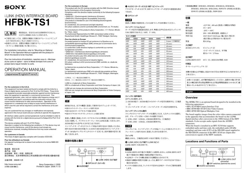
Functions of the BKPF-292
Adjusting functions for input signals
The input level, delay and channel exchange, output
phase inversion, and mix adjustments are applied to
the input signals to output.
Control function from PCNS (Processor
Control Network System)
Connected to the PCNS system, the above adjusting
functions can be remotely controlled.
Failsafe signal generating function
If the reference signal input is lost, operation is
maintained using the signal generated by the built-in
oscillator.
ISR function
The board conforms to the ISR (Interactive Status
Reporting) system.

4(E)
Parts Identifications of the Connector Panel
AES/EBU OUT (digital audio output) connectors (BNC type)
These connectors distributes two pairs of 2-channel AES/EBU digital audio
signals to two systems.
The upper connector of each pair is for channels 1/2 and the lower one is for
channels 3/4.
REMOTE connector (BNC type)
To connect to an S-BUS (PN) communication network. Use a commercially
available T-bridge and coaxial cables (BELDEN8281 or equivalents) for
connection.
DAP
BKPF-292
AES/EBU IN
AES/EBU OUT
REMOTE
1
2
CH-
1/2
CH-
3/4
CH-
1/2
CH-
3/4
CH-
1/2
CH-
3/4
AES/EBU IN (digital audio input) connectors (BNC type)
These connectors accept AES/EBU digital audio signals.
The upper connector is for channels 1/2 and the lower one is for channels 3/4.
Note
Supply signals that are synchronized with each other for channels 1/2 and
channels 3/4. If the signals are not synchronized, noise may be generated.

5(E)
Specifications
General
Operating temperature
5°C to 40°C (41°F to 104°F)
Storage temperature –20°C to +60°C
(–4°F to +140°F)
Operating humidity 10% to 90%
Dimensions Board: 195 × 310 mm (73/4×
121/4inches) (h/d)
Connector panel: 195 × 50 mm
(73/4× 2 inches) (h/d)
Mass Board: approx. 500 g (1 lb 2 oz)
Connector panel: approx. 150 g
(5 oz)
Power requirements +5 V DC: 750 mA
–5 V DC: 50 mA
(supplied from the PFV-D-series
unit)
Power consumption 4 W
Inputs/outputs
Audio inputs AES/EBU IN CH-1/2, CH-3/4:
BNC type (2)
AES/EBU-format digital audio
signal
48 kHz/20 bits, 75 ohms
1 Vp-p±10%, unbalanced
Outputs AES/EBU OUT CH-1/2, CH-3/4:
BNC type (4)
AES/EBU-format digital audio
signal
48 kHz/20 bits, 75 ohms
1 Vp-p±10%, unbalanced
Remote REMOTE: BNC type (1)
S-BUS (PN) control signal
Audio characteristics
Sampling frequency 48 kHz
Quantization bits 20 bits
Minimum input/output delay
4 units of sampling
Control functions
Audio level ±6 dB/±12 dB/+6 dB to –∞/+12
dB to –∞(The variable range is
selected with an internal switch.)
Input channel selection
4 inputs/4 outputs
Phase inversion 0°or 180°at each output
Channel mixing Output channel mixing between
channels 1 and 2 or channels 3
and 4
Delay
Setting method 16-step time setting and step unit
setting with internal switches
Maximum delay With 1-field unit: 15 fields
With 1/2-field unit: 7.5 fields
With 1/4-field unit: 3.75 fields
With 1/8-field unit: 1.875 fields
ISR Output information
Status message: 6 items
Setup message: 1 item
Design and specifications are subject to change
without notice.


The material contained in this manual consists of
information that is the property of Sony Corporation and is
intended solely for use by the purchasers of the equipment
described in this manual.
Sony Corporation expressly prohibits the duplication of any
portion of this manual or the use thereof for any purpose
other than the operation or maintenance of the equipment
described in this manual without the express written
permission of Sony Corporation.
Le matériel contenu dans ce manuel consiste en
informations qui sont la propriété de Sony Corporation et
sont destinées exclusivement à l’usage des acquéreurs de
l’équipement décrit dans ce manuel.
Sony Corporation interdit formellement la copie de quelque
partie que ce soit de ce manuel ou son emploi pour tout
autre but que des opérations ou entretiens de l’équipement
à moins d’une permission écrite de Sony Corporation.
Das in dieser Anleitung enthaltene Material besteht aus
Informationen, die Eigentum der Sony Corporation sind,
und ausschließlich zum Gebrauch durch den Käufer der in
dieser Anleitung beschriebenen Ausrüstung bestimmt sind.
Die Sony Corporation untersagt ausdrücklich die
Vervielfältigung jeglicher Teile dieser Anleitung oder den
Gebrauch derselben für irgendeinen anderen Zweck als die
Bedienung oder Wartung der in dieser Anleitung
beschriebenen Ausrüstung ohne ausdrückliche schriftliche
Erlaubnis der Sony Corporation.

Sony Corporation
Broadcasting & Professional Systems Company
Printed in Japan
1999.07.13
1999
BKPF-292 (SY, 和, 英)
3-868-041-01(1)
Table of contents
Languages:
Other Sony Computer Hardware manuals

Sony
Sony PCWA-C100 User manual

Sony
Sony HR-GP5 User manual

Sony
Sony HKSR-5103 User manual

Sony
Sony XDBK-104 User manual

Sony
Sony MSAC-PR1 User manual

Sony
Sony HFBK-SD1 User manual

Sony
Sony DVBK-2000 User manual

Sony
Sony BPU-4500A User manual

Sony
Sony PCWA-C800S Read This First Quick start guide

Sony
Sony PCM-601ESD User manual

Sony
Sony HFBK-HD1 User manual

Sony
Sony VAIO PCWA-C800S Instruction sheet

Sony
Sony HKSR-5803HQ User manual

Sony
Sony BKPF-L752 User manual

Sony
Sony DMW-S01NL User manual

Sony
Sony PCWA-C100 User manual

Sony
Sony ESBK-7051 User manual

Sony
Sony PCWA-C700 - Wireless Lan Dual Pc Card User manual

Sony
Sony MPE-200 User manual

Sony
Sony BPU4800 User manual