manuals.online logo
Brands
  1. Home
  2. •
  3. Brands
  4. •
  5. Sony
  6. •
  7. Computer Hardware
  8. •
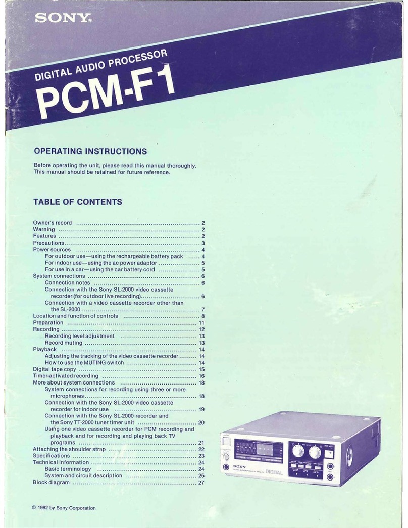
  9. Sony PCM-F1 User manual

Sony PCM-F1 User manual

OPERATING
INSTRUCTIONS
page
2
Before
operating
the
unit,
please
read
this
manual
thoroughly.
This
manual
should
be
retained
for
future
reference.
MODE
D’EMPLOI
Page
26
Avant
la
mise
en
service
de
l'appareil,
lire
attentivement
ce
mode
d’emploi.
Conserver
ce
manuel
pour
toute
référence
ultérieure.
BEDIENUNGSANLEITUNG
ss
seite
50
Lesen
Sie
vor
der
Inbetriebnahme
des
Gerats
diese
Bedienungsan-
leitung
sorgfaltig
durch,
und
bewahren
Sie
sie
zum
spateren
Nach-
schlagen
gut
auf.
MANUAL
DE
INSTRUCCIONES
Pagina
74
Antes
de
utilizar
la
unidad,
lea
detenidamente
este
manual,
y
con-
sérvelo
para
futuras
referencias.
YUNA
PCMF1
3002442
SONY
BDA
photocopy
for
service-use
only
©
1982
by
Sony
Corporation
BIO4
WARNING
To
prevent
fire
or
shock
hazard,
do
not
expose
the
unit
to
rain
or
moisture.
To
avoid
electrical
shock,
do
not
open
the
cabinet.
Refer
servicing
to
qualified
personnel
only.
TABLE
OF
CONTENTS
Features
-cecewccas
eetiet
sha
siate
be
dityhaeeteascbare
slider
pened
feeds
etaetaaiels
2
Operating
voltage
of
the
supplied
ac
power
adaptor..................
3
PLECAUTIONS
25
vicceciwsedeecgesa
vsdensevscuas
die
vaers
daseesiduverssiiereaesacees
3
POW@SSOULCES
>
vice
scavendiacatenncacenesnatcwnsdagsieesésocestesancdivagsceee
4
For
outdoor
use—using
the
rechargeable
battery
pack
......
4
For
indoor
use—using
the
ac
power
adaptor
...............:0.06
5
For
use
in
a
car—using
the
car
battery
cord
................000
5
SYStEM
CONNECHIONS
.........
cece
cece
ec
eee
e
sete
ee
eceneeeeeeeeeeereeaeueees
6
GCOnn@ctiOn:
NOteS:
cz.2..itocd.
Seceseeee
ceecncieenccnaavelaes
ale
ideees
6
Connection
with
the
Sony
SL-F1
series
video
cassette
recorder
(for
outdoor
live
recOrding)..........-..cceeeeeeeeeeee
ee
6
Connection
with
a
video
cassette
recorder
other
than
the
Sl-F1
Series
wks
es
wostewcvunes
decdecccty
aacnegensseueee
ees
7
Locationand
function
of
ControlS
..........
ccc
cece
ee
ee
eee
eeeee
eee
ee
ees
8
PLE
PAlAation:
io
.ecsicdeveeead
ec
seated
agence
dansuak
sVaiaanee
steee
ea
epksccbsauieys
11
PROCOPGING
hiirece
ds
yee
carr
nweg
cnertis
ene
ce/cincncecinvenistrittneeetcacs
de
edetereclored
12
Recording
fevel
adjuStMent
oo...
eeceeeeeeeeeee
eee
eee
eee
eea
ees
13
RECO
MULING:
cieccavesscveecsteadedecesensie
Seco
cdsvoneapeeces
beset
13
PlayDack:
-
ic
ciserdGu
cocaine
doe
lolobsedtew
gree
jaded
aidtaeeeevieerees
14
Adjusting
the
tracking
of
the
video
cassette
recorder.........
14
Howto
use
the
MUTING
SWitch
.........
cece
eee
ee
eee
e
cent
ees
14
Digital
tape
COPY
sci
vc
tie das
Mined
denveed
scons
ape
cdewensineitinemealetie’
esses
15
Timer-activated
reCOrding
.........:cccceeceeeeeeeeeeecee
ease
ee
eeeeenenes
16
More
about
system
connections
System
connections
for
recording
using
three
or
more
MIGTOPNONES
vases
cued
sepesesaewereenpentctueenccese
ancestor
neti
18
Connection
with
the
Sony
SL-F1
series
video
cassette
recorder
forindOoOruS@
oo...
eee
eeceeee
eee
ccc
cece
eee
eee
eneeeneeees
19
Connection
with
the
Sony
SL-F1
series
recorder
and
the
Sony
TT-F1
series
tuner
timer
unit
.........
0a
20
Attaching
the
shoulder
Strap
...........c
ccc
cecee
eee
cece
eee
eee
eeeeee
ees
21
SPeCifi
Cations.
cre
céaciiseee
ad
cue
ciserseeee
cedsudeacevpeccodevetacseeecess
Technical
information
Basic
terminology
System
and
circuit
deScription
.........
cece
eee
ee
eee
ee
eee
teeters
24
LTT
Xel
ao
t-(0]
=|
98
FEATURES
In
conventional
analog
recording
systems,
the
quality
of
sound
reproduction
depends
upon
the
properties
of
magnetic
tape
and
heads,
so
that
it
is
virtually
impossible
to
bypass
the
inherent
limitations
of
conventional
analog
recording,
including
its
limited
dynamic
range
and
frequency
response,
and
its
associated
distor-
tion.
The
Pulse
Code
Modulation
(PCM)
system
points
the
way
to
a
new
era
in
sound
reproduction.
It
can
offer
performance
and
fidelity
far
superior
to
any
analog
system.
In
the
PCM
system,
sound
levels
are
converted
to
a
series
of
binary
codes.
This
information
is
recorded
as
digital
pulses
of
equal
amplitude.
In
playback,
all
that
has
to
be
done
is
to
discriminate
between
the
presence
and
absence
of
a
pulse.
The
quality
of
recording
and
playback
is
thus
not
dependent
on
the
characteris-
tics
of
tape
and
heads.
The
PCM-F1
is
the
newest
addition
to
Sony’s
line
of
PCM
digital
audio
processors
for
consumer
applications.
With
the
PCM-F1,
hi-fi
sound
reproduction
with
wide
dynamic
range,
minimal
distortion,
low
wow
and
flutter
(lower
than
the
measurable
limit),
and
flat
fre-
quency
response
is
achieved.
Listening
to
the
reproduction
of
your
PCM-F1
is
just
like
being
in
the
concert
hall.
Compact,
lightweight
PCM
digital
audio
processor
In
conventional
digital
audio
processors,
several
hundreds
of
ICs
are
employed
in
digital
processing
circuitry,
which
makes
it
dif-
ficult
to
make
the
unit
compact
and
lightweight.
;
The
three
new
LSls
for
digital
processing
developed
especially
for
digital
audio
processor
use
have
successfully
made
the
PCM-F1
compact
and
lightweight.
The
A/D
(analog-to-digital)
and
D/A
(digital-to-analog)
converters,
which
are
newly
developed
mono-
lithic
ICs,
are
especially
adaptable
to
mass
production.
This
results
in
the
production
of
a
PCM
digital
audio
processor
that
is
more
af-
fordable
to
a
greater
proportion
of
audiophiles.
Resolution
selector
for
recording
and
playback
with
wider
dynamic
range
and
less
distortion
The
PCM-F1
was
developed
in
accordance
with
the
technical
spec-
ifications
of
the
Electronic Industries
Association
of
Japan
(ElAu),
which
has
adopted
the
14-bit
linear
quantization
format.
In
addi-
tion,
the
unit
has
the
capability
of
recording
and
playing
back
in
ac-
cordance
with
the
16-bit
linear
quantization
format
with
wider
dynamic
range
and
less
distortion
than
the
14-bit
format.
The
14-bit
and
16-bit
formats
can
be
selected
with
the
RES
(resolution)
selec-
tor.
Three
different
power
sources
The
unit
can
be
operated
on
three
different
power
sources:
house
current
using
the
supplied
ac
power
adaptor,
optional
echargeable
battery
pack,
and
12V
car
battery
using
an
optional
car
battery
cord.
When
this
compact,
lightweight
PCM-F1
is
combin
ed
with
the
Sony
SL-F1
series
portable
video
cassette
recorder,
you
can
make
a
live
field
recording
with
wide
dynamic
range,
minimal
distortion,
and
flat
frequency
response.
Stable
power
supply
Two
dc-to-de
converters
incorporated
in
the
unit—one
5
V)
for
the
digital
circuitry
and
the
other
(£15
V)
for
the
analoy
circuitry—
assure
stable
power
supply.
Easy
tracking
adjustment
of
video
heads
Correct
tracking
adjustment
of
the
video
heads
can
te
easily
per-
formed
by
observing
a
meter.
Muting
switch
for
continuous
sound
reproduction
With
the
MUTING
switch
set
to
OFF,
the
reproduced
jound
is
not
cut
off
even
if
many
dropouts
occur,
or
if
the
tapes
not
being
transported
at
the
proper
playback
speed.
¢
Record
muting
function
allows
you
to
easily
insert
a
blank
space
between
selections.
Multi-generation
digital-to-digital
tape
copy
can
be
performed
with
absolutely
no
deterioration
in
signal
quality.
With
the
highly
perfected
error
detection
and
correction
circuits
in-
corporated,
the
reproduced
sound
quality
is
not
affected
by
dropout
errors.
You
can
choose
either
of
two
ways
to
have
the
peak
level
indicated
on
the
LED
peak
program
meters.
Microphone
head
amplifiers
are
incorporated
for
recording
directly
from
microphones
and
provide
excellent
sound
quality.
:
OPERATING
VOLTAGE
OF
THE
SUPPLIED
~AC
POWER
ADAPTOR
Before
connecting
the
supplied
ac
power
adaptor
to
the
power
'
source,
check
that
the
operating
voltage
of
your
unit
is
the
same
as
-
the
local
power
line
voltage.
:
The
Continental
European
model
(type
1)
operates
on
220
V
ac
(or
240
V
ac
adjustable
by
authorized
Sony
personnel).
|
The
United
Kingdom
model
(type
2)
operates
on
240
V
ac
(or
220
V
ac
adjustable
by
authorized
Sony
personnel).
TURNING
THE
AC
POWER
ADAPTOR
ON
AND
OFF
The
POWER
switch
on
the
rear
panel
of
the
ac
power
adaptor
is
the
mains
power
on/off
switch.
To
turn
on
the
ac
power
adaptor,
set
the
POWER
switch
to
ON
first
and
depress
the
ON/STAND-
BY
switch.
When
the
POWER
switch
is
set
to
OFF,
the
power
supply
to
the
unit
is
shut
off
so
that
the
unit
is
not
turned
on
even
if
the
ON/STANDBY
switch
is
depressed.
For
the
Customers
in
the
United
Kingdom
Important
The
wires
in
this
mains
lead
are
coloured
in
accordance
with
the
following
code.
Blue:
Neutral
Brown:
Live
As
the
colours
of
the
wires
in
the
mains
lead
of
this
apparatus
may
not
correspond
with
the
coloured
markings
identifying
the
ter-
minals
in
your
plug,
proceed
as
follows:
The
wire
which
is
coloured
blue
must
be
connected
to
the
terminal
which
is
marked
with
the
letter
N
or
coloured
black.
The
wire
which
is
coloured
brown
must
be
connected
to
the
terminal
which
is
mark-
ed
with
the
letter
L
or
coloured
red.
PRECAUTIONS
On
color
broadcasting
systems
The
unit
is
designed
to
be
used
with
a
video
cassette
recorder
using
the
PAL
or
SECAM
color
standard.
Recording
and
playback
with
a
recorder
based
on
other
color
systems
cannot
be
done.
On
safety
@
Operate
the
unit
only
on
12
V
dc.
For
ac
operation,
use
only
the
ac
power
adaptor
supplied
with
the
unit.
Do
not
use
any
other
ac
power
adaptor.
For
car
battery
operation,
use
only
the
car
battery
cord
recom-
mended
for
this
unit.
Do
not
use
any
other
car
battery
cord.
@
The
nameplate
indicating
operating
voltage,
power
consumption,
etc.
is
located
on
the
bottom.
@
Should
any
liquid
or
solid
object
fall
into
the
cabinet
of
the
unit
or
the
ac
power
adaptor,
unplug
the
units
and
have
them
checked
by
qualified
personnel
before
operating
them
any
further.
@
Unplug
the
ac
power
adaptor
from
the
wall
outlet
if
it
is
not
to
be
used
for
an
extended
period
of
time.
To
disconnect
the
cord,
pull
it
out
by
grasping
the
plug.
Never
pull
the
cord
itself.
On
installation
®
Do
not
install
the
unit
and
the
ac
power
adaptor
in
a
location
near
heat
sources
such
as
radiators
or
air
ducts,
or
in
a
place
subject
to
direct
sunlight,
excessive
dust,
mechanical
vibration
or
shock.
@
Good
air
circulation
is
essential
to
prevent
internal
heat
build-up
in
the
unit
and
the
ac
power
adaptor.
Place
these
units
in
a
location
with
adequate
air
circulation.
Do
not
place
the
ac
power
adaptor
on
a
soft
surface,
such
as
a
rug,
that
would
block
the
ventilation
slots
on
the
bottom.
®
Do
not
place
anything
on
top
of
the
cabinets.
The
top
ventilation
slots
of
the
ac
power
adaptor
must
be
unobstructed
for
proper
operation
of
the
unit
and
to
prolong
the
life
of
its
components.
On
operation
@
Before
making
connections,
be
sure
to
turn
off
each
component.
@The
PCM
digital
audio
processor
incorporates
a
shield
which
suppresses
the
radiation
of
the
high-frequency
signal
used
in
the
pulse-code
modulation
process.
However,
the
unit
may
still
possibly
interfere
with
an
AM/FM
tuner
or
a
television
set.
If
recep-
tion
interference
occurs,
move
the
unit
away
from
the
affected
component.
@
The
muting
circuitry
of
the
unit
may
activate
if
a
vacuum
cleaner,
electric
shaver,
transceiver
or
similar
device
causes
interference.
@
When
the
unit
is
not
being
used,
turn
the
power
off
to
conserve
energy
and
to
extend
the
life
of
your
unit.
On
cleaning
Clean
the
cabinet,
panel
and
controls
with
a
soft
cloth
lightly
moistened
with
mild
detergent
solution.
Do
not
use
any
type
of
abrasive
pad,
scouring
powder
or
solvent
such
as
alcohol
or
ben-
zine.
On
repacking
Do
not
throw
away
the
carton
and
the
packing
material.
It
makes
an
ideal
container
to
transport
the
unit.
When
shipping
the
unit
for
repair
work
or
to
another
location,
repack
it
as
illustrated
on
the
carton
box.
If
you
have
any
questions
or
problems
concerning
your
unit,
please
contact
your
nearest
Sony
dealer.
POWER
SOURCES
The
unit
can
be
operated
on
any
one
of
the
following
power
sources:
—AC
power
supply
using
the
AC-700
ac
power
adaptor
(supplied)
—Sony
NP-1
rechargeable
battery
pack
(optional)
—12V
car
battery
using
the
Sony
DCC-2500
car
battery
cord
(optional)
FOR
OUTDOOR
USE—USING
THE
RECHARGEABLE
BATTERY
PACK
Important
points
to
remember
leferse
ibe
cated
@
Be
sure
to
prepare
spare
battery
packs,
since
you
may
make
pack
(optional).
recordings
for
a
longer
time
than
you
intended.
A
fully-charged
battery
pack
powers
the
unit
for
about
an
hour.
=,
@
If
an
external
power
source
is
connected
to
this
unit
with
the
battery
pack
installed
in
the
unit,
the
external
power
source
has
priority
over
the
battery
pack,
and
the
battery
pack
will
be
disconnected.
@
If
the
ON
switch
of
this unit
is
pressed
while
the
battery
pack
Press
to
remove
i
:
: : ;
oetals
the
battery
pack.
is
being
charged,
the
charging
will
stop
and
the
unit
will
be
turn-
ed
on.
Before
operating
the
unit,
be
sure
to
recharge
the
battery
pack.
Recharging
the
battery
pack
Depress
to
turn
the
power
on.
:
The
built-in
indicator
will
light
up.
2
Set
the
POWER
switch
to
ON.
to
a
wall
outlet
4
Turn
the
power
off.
The
illuminated
indicators
will
go
off.
AC
power
adaptor
AC-700
(supplied)
insert
the
battery
pack.
The
CHARGE
indicator
illuminates
during
charging.
[
Press
the
CHARGE
button.
The
CHARGE
indicator
will
light
up
and
charging
will
begin.
The
charging
time
is
about
1
hour
at
normal
temperatures.
To
check
the
battery
pack
condition
When
the
battery
pack
is
fully
charged,
the
charging
will
stop
Turn
on
the
unit,
keep
the
BATT
CHECK
button
dejressed
and
automatically
and
the
CHARGE
indicator
will
go
off.
observe
the
upper
LED
meter.
Battery
life
tas
Recharge
the
batt
k
At
normal
temperatures,
a
fully-charged
battery
provides
1
hour
of
Good
battery
condition
eplecewilta
sulivcciraean
aiib:
continuous
operation
of
the
unit.
If
the
LED
below
“E”
illuminates,
the
unit
will
be
automatically
turned
The
battery
pack
is
fully
off
in
several
minutes.
BATT
CHECK
charged.
_
f
BATT
CHECK
Et:
10
6 3
BATT
CHECK
ree
eeD
UVOUOVT
STEVEN
20
10
it}
FOR
INDOOR
USE—USING
THE
AC
POWER
ADAPTOR
Turn
off
the
ac
power
adaptor
when
connecting
or
disconnecting
wae
AC
power
adaptor
AC-700
(supplied)
Align
the
guide
pin
with
the
upper
slot,
then
insert
the
plug
firmly.
ae
LLY
C,
ie
@
FOR
USE
IN
A
CAR—USING
THE
CAR
BATTERY
CORD
Car
with
a
12
V
car
battery
Car
battery
cord
DCG-2500
(optional)
<a
=m
Q
to
a
cigarette
lighter
socket
Oo
Insert
the
plug
firmly,
aligning
the
guide
pin
with
the
upper
siot.
For
details,
refer
to
the
instruction
manual
of
the
car
battery
cord.
This
unit
has
a
relatively
high
power
consumption
for
a
portable
unit.
Be
careful
that
the
car
battery
does
not
become
completely
discharged.
SYSTEM
CONNECTIONS
CONNECTION
NOTES
@
Turn
off
the
amplifier
before
making
connections.
@
The
supplied
connecting
cords
with
red
and
white
plugs
are
for
audio
signals,
and
those
with
yellow
plugs
are
for
video
signals.
@
Be
sure
to
connect
the
red
plug
of
the
supplied
audio
connect-
ing
cord
to
the
right-channel
[R]
jack
and
the
white
plug
to
the
left-channel
[{L]
jack.
:
@
To
connect
the
unit
with
the
Sony
SL-F1
series
video
cassette
recorder,
use
the
supplied
VMC-110C
video
connecting
cord.
To
connect
the
unit
with
a
video
cassette
recorder
other
than
the
/
RES
selector
SL-F1
series,
use
the
supplied
video
connecting
cords
with
a
BNC-type
plug
and
a
phono
plug.
The
yellow
plugs
of
the
VMC-110C
are
labelied
to
indicate
the
signal
flow.
The
plug
labelled
VIDEO
IN
should
be
connected
to
the
VIDEO
OUT
jack
of
this unit
and
the
one
labelled
VIDEO
OUT
to
the
VIDEO
IN
jack.
to
the
accessory
connector
of
the
video
cassette
recorder
to
VIDEO
OUT
of
this
unit
for
right
for
left
channel
channel
eB
Microphones
op
col
Video
cassette
recorder
SL-F1
series
WAYS
Marked
“VIDEO
OUT”
For
indoor
use
with
the
Sony
SL-F1
series
recorder
and
additional
audio
components,
refer
to
‘Connection
with
the
Sony
SL-F1
series
video
cassette
recorder
for
indoor
use”
on
page
19.
=e
COND
|
H
i
|
———S
a
Marked
“VIDEO
IN”
ACCESSORY
CONNECTOR
TIMER
REC
switch:
Set
to
OFF.
Video
connecting
cord
VMC-110C
(supplied)
@
The
cabie
connectors
should
be
fully
inserted
into
the
jacks.
.
A
loose
connection
may
cause
hum
and
noise.
@
Keep
the
connecting
cords
away
from
the
power
cords
or
speaker
cords
to
avoid
hum
pick-up,
and
maintain
a
moderate
_
separation
between
the
connecting
cords
and
any
antenna
lead-
. .
:
in
to
avoid
possible
noise
pick-up.
Keep
the
cables
as
short
as
.
practical.
'
@We
recommend
using
the
Sony
SL-F1
series
‘portable
videt.
;
cassette
recorder
or
any
other
Sony
video
cassette
recorder.
"Also,
we
recommend
the
use
of
L-500,
L-250
and
L-125
video.
ees
_
tapes
but
not
longer
tapes,
for
optimum
results.
.
PCM-F1
C2.
FF
mOsm
|
Ni
Audio
connecting
cords.
RK-112
(supplied)
Amplifier
~
RES
selector
Video
cassette
recorder
TAPE
RECORDER
1
oa
we:
wm
REC
OUT,
e
For
detailed
information:
about
connections
of
the
video
cassette
recorder
and
amplifier,
refer
to
the
instruction
manual
©
supplied
with
each
unit.
:
:
|
CONNECTION
WITH
A
VIDEO
CASSETTE
RECORDER
OTHER
THAN
THE
SL-F1
SERIES
AC
power
adaptor
AC-700
(supplied)
_--~-~
POWER
switch
to
a
wall
outlet
“=
Video
connecting
cords
with
a
BNC-type
plug
and
a
phono
plug
(supplied)
to
a
wall
outlet
/
PCM
recording
switch:
PCM/LINE
———
Speaker
system
to
a
wail
outlet
LOCATION
AND
FUNCTION
OF
CONTROLS
Before
plugging
in
or
attempting
to
operate
the
unit,
we
suggest
that
you
familiarize
yourself
with
all
its
switches
and
controls.
Each
number
in
the
photo
is
keyed
to
the
descriptive
text.
FRONT
PANEL
EMPHA
SONY
DIGITAL
ALLOIO
’®
MUTE
(muting)
indicator
O
ON
(power)
switch
@
ON
(power)
switch
Press
to
turn
on
the
power.
The
LED
peak
program
meters
will
il-
luminate.
To
turn
the
power
off,
press
the
switch
again.
@
HEADPHONES
ATT
(attenuation)
control
This
control
adjusts
the
volume
at
the
headphones.
At
the
“0”
posi-
tion,
the
rated
output
is
obtained.
When
this
control
is
set
to
the
“6”
position,
the
level
is
reduced
by
6
dB,
and
by
setting
it
to
“12”,
“18”
or
“24”,
the
level
is
reduced
by
that
amount
of
decibels
from
the
rated
output
obtained
at
the
“0”
position.
@
HEADPHONES
jack
(stereo
phone
jack)
Headphones
may
be
inserted
either
to
monitor
the
input
signals
to
be
recorded
or
to
listen
to
a
recording
in
the
playback
mode.
@
MUTE
(muting)
indicator
If
the
video
cassette
recorder
is
not
transporting
tape
at
the
proper
playback
speed
(for
example,
when
the
tape
first
begins
to
move),
or
if
many
dropouts
occur,
this
indicator
will
light
up.
When
the
in-
dicator
lights
up
with
the
MUTING
switch
set
to
ON,
the
muting
cir-
cuit
will
activate.
@
EMPHASIS
indicator
When
recording
and
playback
are
made
with
this
unit,
the
em-
phasis
circuit
incorporated
in
the
unit
activates
during
recording
(pre-emphasis)
and
playback
(de-emphasis)
and
the
EMPHASIS
in-
dicator
illuminates.
When
a
tape
recorded
without
pre-emphasis
with
a
PCM
digital
audio
processor
other
than
this unit
is
played
back
with
this
unit,
the
EMPHASIS
indicator
will
not
illuminate.
HEADPHONES
ATT
(attenuation)
control
1
LED
peak
program
meters
¥—
TRACKING
indicator
[
COPY
PROHIBITING
indicator
KD
EMPHASIS
indicator
©
HEADPHONES
jack
(stereo
phone
jack)
@COPY
PROHIBITING
indicator
When
a
tape
with
a
tape
copy
prohibiting
code
is
played
back,
this
indicator
will
light
up
to
show
that
a
digital
tape
copy
cannot
be
made.
@
TRACKING
indicator
When
you
press
the
METER
selector,
the
lower
LED
peak
program
meter
will
be
changed
to
a
tracking
meter,
and
the
TRACKING
in-
dicator
will
light
up.
@LED
peak
program
meters
These
meters
show
the
peak
input
level
of
each
channel
during
recording,
and
the
recorded
level
during
playback.
They
follow
the
transient
peaks
of
high-level
inputs
that
are
too
brief
to
be
followed
by
conventional
VU
meters
so
that
the
optimum
recording
level
can
be
accurately
set.
For
easy
reading,
the
meters
hold
tne
highest
peak
while
indicating
the
varying
levels
lower
than
the
peak.
While
the
BATT
CHECK
button
is
kept
depressed,
the
upper
meter
for
the
left
(L})
channel
shows
the
battery
pack
condition.
When
the
METER
selector
is
pressed,
the
lower
meter
for
the
right
(R)
channel
shows
the
tracking
condition
of
the
video
cassette
recorder.
*
+
BARAT,
c
|
.
OREC
(recording)
LEVEL
controls
These
controls
adjust
the
recording
level.
The
left
knob
is
for
the
'
left
channel
and
the
right
knob
for
the
right
channel.
'
@REC
MUTE
(record
muting)
button
and
indicator
Keep
this
button
depressed
to
eliminate
unwanted
material
and
to
insert
a
blank
space
during
recording.
While
the
button
is
kept
depressed,
the
REC
MUTE
indicator
will
illuminate.
See
“‘Record
muting”
on
page
13.
'
@
METER
selector
Press
to
turn
the
LED
peak
program
meters
into
a
tracking
meter.
Each
time
the
selector
is
pressed,
the
function
of
the
meter
will
change.
@MUTING
switch
Normally
set
this
switch
to
ON.
If
the
video
cassette
recorder
is
not
transporting
tape
at
the
proper
playback
speed,
or
if
many
dropouts
occur
due
to
the
mistracking
of
the
video
heads
of
the
video
cassette
recorder,
or
due
to
scratch-
es
and
dust
on
the
magnetic
tape,
the
muting
circuit
will
activate
and
the
reproduced
sound
will
be
cut
off.
If
you
do
not
want
the
reproduced
sound
to
be
cut
off
by
the
muting
circuit,
set
the
switch
to
OFF.
See
“How
to
use
the
MUTING
switch”
on
page
14.
@®
PEAK
HOLD
RESET
buttons
You
can
choose
either
of
two
ways
to
have
the
peak
level
indicated:
When
the
AUTO
button
is
pressed,
successive
peaks
are
held
for
about
1.7
seconds,
except
when
a
higher
peak
occurs
before
1.7
'
seconds
have
passed,
in
which
case
that
peak
is
immediately
in-
dicated.
When
the
power
is
first
turned
on,
the
AUTO
peak
indica-
tion
mode
will
automatically
operate.
9
REC
(recording)
LEVEL
controls
tI!)
REC
MUTE
(record
muting)
button
and
indicator
49)
MIC
jacks
(phone
jacks)
UL)
BATT
(battery)
CHECK
button
tk)
INPUT
selector
1)
COPY
(digital
tape
copy)
switch
(K)
PEAK
HOLD
RESET
buttons
(
Mutine
switch
th)
METER
selector
When
the
MANUAL
button
is
pressed,
the
peak
level
will
be
held
on
the
scale
until
a
higher
peak
occurs,
and
that
peak
will
be
held.
To
reset
the
peak
held
on
the
meter,
just
press
this
button.
You
will
find
this
method
of
indicating
the
peak
input
useful
when
you
want
to
know
the
highest
peak
of
a
tape
or
disc,
or
when
you
want
to
know
both
the
highest
peak
as
well
as
the
intermittent
input
levels
during
live
recording.
@cOPY
(digital
tape
copy)
switch
Set
this
switch
to
ON
for
digital-to-digital
tape
copy,
with
absol
ute-
ly
no
deterioration
in
signal
quality,
using
a
pair
of
video
cassette
recorders
and
the
COPY
OUT
jack
at
the
rear.
Be
sure
to
set
this
switch
to
OFF
except
during
digital
tape
copy.
With
this
switch
set
at
the
ON
position,
no
signal
is
obtained
at
the
VIDEO
OUT
jack.
See
“DIGITAL
TAPE
COPY”
on
page
15.
@INPUT
selector
LINE:
to
record
through
the
LINE
IN
jacks
at
the
rear.
MIC:
to
record
through
the
MIC
jacks.
@
BATT
(battery)
CHECK
button
While
this
button
is
kept
depressed,
the
upper
meter
shows
the
bat-
tery
pack
condition.
@
MIC
jacks
(phone
jacks)
Any
low-impedance
microphone
equipped
with
a
phone
plug
may
be
used.
If
your
microphone
is
equipped
with
a
mini
plug,
you
will
need
a
plug
adaptor.
REAR
PANEL
VIDEO
IN
jack
VIDEO
OUT
jack
LINE
OUT
jacks
LINE
IN
jacks
DC
IN
12V
(dc
input)
connector
RES
(resolution)
selector
Selects
the
resolution
for
recording.
14
BIT:
for
recording
in
accordance
with
the
technical
specifica-
tions
of
the
Electronic
Industries
Association
of
Japan
(EIAJ)
COPY
OUT
(tape
copy
output)
jack
which
has
adopted
the
14-bit
linear
quantization
format.
To
perform
digital-to-digital
tape
copy,
connect
this
jack
with
the
Set
the
selector
to
this
position
when
the
tape
recorded
with
video
input
jack
of
the
video
cassette
recorder
for
recording
so
that
this
unit
is
to
be
played
back
using
another
PCM
digital
audio
when
the
COPY
switch
is
set
to
ON,
playback
signals
in
which
er-
processor
which
conforms
to
the
14-bit
quantization
format
of
rors
are
corrected
and/or
concealed
are
obtained.
the
EIAJ.
Be
sure
not
to
use
this
jack
except
during
digital
tape
copy.
Normal
16
BIT:
for
recording
and
playing
back
using
this
unit
with
a
wider
recording
and
playback
cannot
be
performed
using
this
jack.
dynamic
range
and
less
distortion.
Normally
set
the
selector
to
this
position.
During
playback,
it
is
not
necessary
to
select
the
position
of
this
selector,
since
the
14-bit
or
16-bit
format
used
for
recording
is
automatically
selected.
For
detailed
information,
refer
to
page
24.
AC
POWER
ADAPTOR
AC-700
(SUPPLIED)
AC
power
cord
CHARGE
button
and
indicator
DC
OUT
cord
Press
to
start
charging
the
battery
pack.
The
indicator
illuminates
during
charging.
POWER
switch
Set
this
switch
to
ON
to
supply
ac
(mains)
power
to
the
unit.
Set
it
to
OFF
to
cut
the
ac
power
completely.
ON/STANDBY
switch
and
indicator
Depress
to
turn
on
the
unit
after
setting
the
POWER
switch
to
ON.
The
built-in
indicator
will
light
up.
Press
the
switch
again
so
that
the
unit
is
in
the
standby
mode.
The
indicator
will
go
off.
10
PREPARATION
For
detailed
information
about
the
operation
of
the
video
cassette
recorder,
refer
to
its
instruction
manual.
RES
switch
(at
the
rear):
Normally
set
to
“16
BIT”.
MUTING
switch:
ON
COPY
switch:
OFF
PCM
recording
switch:
PCM
\
Video
cassette
recorder
Mo,
selector:
LINE/PCM
{
|
\
\
i
|
|
Important
points
to
remember
...
:
oe
ws
@The
COPY
switch
should
be
used
only
for
digital
-to-
digital:
tape
copy.
For
normal
recording
and
playback,
be
sure
to
set
the
COPY
switch
to
OFF,
:
When
the
switch
is
set
to
ON,
recording
cannot
be
made
ane.
ae
reproduced
sound
may
be
somewhat
distorted.
eet
:
@
The
pause
function
of
the
video
cassette
recorder
is
conven:
ient
for
more
accurate
start
of
recording
and
to
stop
momentari-
ly
during
playback.
However,
the
tape
may
be
damaged
if
it
is
stopped
for
an
extended
period
of
time.
We
recommend
that
the
pause
function
be
used
only
when
absolutely
necessary:
Note
that
during
the
pause
mode,
the
muting
function.
of
the
unit
may
not
operate
well
with
some
video,
cassette
fecordersy,
and
the
reproduced
sound
may
be
enol
-
:
RECORDING
For
detailed
information
about
the
operation
of
the
video
cassette
recorder,
refer
to
its
instruction
manual
Follow
the
numbered
sequence.
Press
the
ON
switch
(ON).
Turn
on
the
video
cassette
recorder.
Video
cassette
recorder
2
Insert
a
video
cassette.
Set
the
video
cassette
recorder
to
the
recording
mode.
(While
holding
the
record
button
depressed,
press
the
play
button.)
Recording
will
begin.
Set
the
video
cassette
recorder
to
the
record
monitoring
mode.
(Press
the
record
button,
or
press
the
record
and
pause
buttons
simultaneously.)
Select
the
program
source
to
be
recorded.
MIC:
for
recording
through
the
MIC
jacks.
LINE:
for
recording
a
program
source
connected
to
the
LINE
IN
jacks
at
the
rear.
Important
pointa
t
to
remember,
Sere
ete
@
Be
sure
to
connect
both
the
VIDEO
IN
and
VIDEO
OUT
jacks
to
‘the.video
cassette
recorder.
If
the
VIDEO
IN
jack
of
this
unit
is
=:
“not
connected:
‘to-
the
video:
output
of
the
video
cassette
~”
recorder,
recording
is
possible
‘but®
you
cannot
monitor
the”
.
,fecording,
and
the
peak
program
meters
will
not
deflect.
ae
;
details,
ans
to
oe
)
peak
program
meters.’
on.
n
page
24).
12
Play
the
program
source
and
adjust
the
recording
level.
DOOD
ECUGUEL
GN
-<dB
oo
50 40
30
20
SL
r
OVER
03
i
:
Yo
Adjust
the
REC
LEVEL
controls
so
that
the
red
OVER
indicators
on
the
peak
program
meters
do
not
illuminate
at
the
highest
signal
level
(For
details,
refer
to
“Recording
jevel
adjustment”
on
page
13.)
@
Video
cassettes
incorporate
a
safety
tab,
just
as
do
audio
cassettes.
If
the
tab
has
been
removed,
the
record
moce
does
not
function
when
the
record
button
is
pressed.
To
record
on
a’
cassette
which
has
had
the
safety
tab
removed,
simply
cover
the
slot
with
a
piece
of
plastic
tape.
(For
details,
refer
to
the
in-
‘Struction
manual
supplied
with
the
video
cassette
recorder.)
RECORDING
LEVEL
ADJUSTMENT
The
PGM
recording
system
has
no
reference
level,
but
an
absolute
maximum
value
of
0
dB.
If
all
the
input
signals
are
recorded
under
0
dB,
the
PCM-F1
assures
equal
characteristics
at
any
input
level.
This
is
why
the
peak
program
meters
of
this
unit
have
no
plus
in-
dication.
It
must
be
noted
that
the
peak
program
meters
show
the
pre-
emphasized
input
signal
levels.
See
the
diagram
below.
For
this
reason,
it
is
important
to
adjust
the
recording
jevel
so
that
there
will
be
no
clipping
over
0
dB.
(For
details
on
emphasis
and
peak
pro-
gram
meters,
refer
to
page
24.)
Pre-emphasis
(recording)
|!
Ti
=
50
psec
a
[|
Hl
+10
14
+5
0
1
-5
+
~10
Response
in
dB
,
I
LUE
De-emphasis
(playback)
|;
100
500
1k
5k
10k
20k
Frequency
in
Hz
Adjust
the
recording
level
with
the
REC
LEVEL
controls
so
that
the
peak
program
meters
do
not
deflect
over
0
dB.
The
red
illumination
of
the
OVER
indicators
warns
of
an
overload
during
recording.
If
the
indicators
illuminate
frequently,
the
recording
level
setting
is
too
high,
and
this
will
result
in
overloaded
and
distorted
recording.
Intermittent
illumination
presents
no
problem.
If
the
recording
level
setting
is
too
low,
the
recording
will
be
noisy.
The
correct
recording
level
setting
depends
upon
the
program
source
to
be
recorded.
Generally,
adjust
the
level
to
about
—15
dB.
RECORD
MUTING
By
using
the
REC
MUTE
button
during
recording,
you
can
provide
an
interspacing
in
the
recording,
eliminating
unwanted
program
material
such
as
commercials.
While
the
record
muting
is
operating,
the
incoming
signal
is
not
recorded
on
the
tape
but
it
continues
to
register
on
the
meters
and
feed
to
the
monitor
so
that
you
know
exactly
what
is
going
on.
To
insert
a
blank
Hold
down
the
REC
MUTE
button
for
as
long
as
you
want
the
blank
segment
on
the
tape
to
be.
When
you
release
the
button,
the
recording
will
resume.
REC
MUTE
Keep
depressed
for
as
long
as
you
want
the
blank
segment
on
the
tape
to
be.
13
PLAYBACK
For
detailed
information
about
the
operation
of
the
video
cassette
recorder,
refer
to
its
instruction
manual.
Follow
the
numbered
sequence.
Press
the
ON
switch
(ON).
Turn
on
the
video
cassette
recorder
and
amplifier.
recorder
;
Amplifier
i=
a
3
Turn
down
the
volume.
Press
the
TAPE
switch,
|
or
set
the
tape
monitor
|
switch
to
TAPE,
\G&
Adjust
the
volume
to
your
preference.
An
important
point
to
remember
In
the
PCM
system,
a
wider
dynamic
range
is
achieved
than
that
of
the
conventional
analog
system,
and
the
peaks
of
high
level
inputs
are
recorded
with
high-fidelity.
In
addition,
the
noise
level
is
very
low.
ADJUSTING
THE
TRACKING
OF
THE
VIDEO
CASSETTE
RECORDER
When
a
video
tape
recorded
on
another
video
cassette
recorder
is
played
back,
dropouts
may
occur
due
to
the
mistracking
of
the
video
heads.
To
obtain
the
optimum
reproduced
sound,
adjust
the
tracking
of
the
video
cassette
recorder
as
follows.
1
Press
the
METER
selector.
The
TRACKING
indicator
will
light
up,
and
the
lower
meter
will
change
to
a
tracking
meter.
2
Insert
the
recorded
video
cassette
and
set
the
video
cassette
recorder
to
the
playback
mode.
After
the
MUTE
indicator
goes
off,
turn
the
tracking
control
of
the
video
cassette
recorder,
observing
the
lower
meter
of
this
unit.
Adjust
the
tracking
con-
trol
so
that
the
rightmost
LED
within
the
adjustable
range
il-
luminates.
reer
iM
!
Itt
I!
I!
|
Loe)
TRACKING/LEVEL
UP
ALUOEEODEUEULT
UTE
1)
Comte
t
S—=
paca)
Righimost
LED
within
the
adjustable
range
For
details
on
the
tracking
adjustment,
refer
to
the
instruction
manual
supplied
with
the
video
cassette
recorder.
14
Video
cassette
2
Insert
a
recorded
video
cassette.
Set
the
video
cassette
recorder
to
the
playback
mode.
(Press
the
play
button.)
Playback
wili
begin.
lf
you
turn
up
the
volume
inadvertently
while
listening
to
a
por-
tion
of
the
tape
where
no
audio
signals
or
very
low
level
inputs
are
recorded,
the
speakers
may
be
damaged
when
the
portion
of
the
tape
with
peak
levels
is
played
back.
HOW
TO
USE
THE
MUTING
SWITCH
Normally
set
the
MUTING
switch
to
ON.
If
the
video
cassette
recorder
is
not
transporting
tape
at
the
proper
playback
speed
(for
example,
when
the
tape
first
begins
to
move,
or
during
variable-
speed
playback,
or
during
pause),
or
if
many
dropouts
occur,
or
ifa
tape
on
which
a
signal
other
than
the
PCM
signal
is
ecorded
is
played
back,
the
muting
circuit
will
activate.
If
the
muting
circuit
activates
so
often
that
the
reproduced
sound
is
frequently
cut
off,
adjust
the
tracking
control
of
the
video
cassette
recorder,
then
set
the
MUTING
switch
to
OFF.
Now
you
can
enjoy
the
reproduced
sound
without
interruption,
though
it
will
be
somewhat
noisy.
If
the
tape
has
been
badly
damaged
(for
example,
if it
has
folds
in
it),
the
sound
may
be
muted
even
if
the
MUTING
switch
is
set
to
OFF.
MUTING
OF
PUTUUE
TD
UEU
EY
%
03
1
10
[ul
25 50
ON
g
wm
SmuTe
|[—=
empHasis.
—
[=
au
DIGITAL
TAPE
COPY
Using
the
COPY
OUT
jack
of
this unit
and
a
pair
of
video
cassette
recorders,
youcan
make
digital-to-digital
tape
copy
with
absolutely
no
deterioration
in
signal
quality.
CONNECTION
oe
Signal
flow
Video
connecting
cords
with
a
BNC-type
plug
and
a
phono
plug
(supplied)
SS
to
video
output
(VIDEO
OUT)
Video
cassette
recorder
for
playback
POWER
switch
to
a
wall
outlet
RES
selector:
Normally
set
to
“16
BIT”.
When
making
a
digital
tape
copy
which
is
to
be
played
back
with
another
PCM
digital
audio
processor
which
conforms
to
the
14-bit
quantization
format
of
the
4
to
video
input
(VIDEO
IN)
Video
cassette
recorder
for
recording
OPERATING
PROCEDURE
1
2
&
Turn
on
the
unit
and
video
cassette
recorders.
Insert
a
recorded
tape
into
the
video
cassette
recorder
for
playback
and
a
blank
tape
into
the
video
cassette
recorder
for
recording.
Set
the
COPY
switch
of
the
PCM-F1
to
ON.
Start
the
playback
of
the
video
cassette
recorder
for
playback
and
the
recording
of
the
video
cassette
recorder
for
recording.
Copying
will
begin.
After
the
tape
copy
has
been
completed,
be
sure
to
set
the
COPY
switch
to
OFF.
Important
points
to
remember
@The
reproduced
sound
being
monitored
through
the
head-
phones
or
speakers
with
the
COPY
switch
set
to
ON
may
be
somewhat
more
distorted
than
when
played
back
and
monitored
with
the
switch
set
to
OFF.
However,
the
tape
will
be
copied
with
no
deterioration
in
signal
quality.
:
@No
recording
level
adjustment
is
necessary
when
making
a
digital-to-digital
tape
copy.
.
@A
tape
on
which
the
tape
copy
prohibiting
code
has
been
recorded
cannot
be
duplicated.
When
such
a
tape
is
played
back,
the
COPY
PROHIBITING
indicator
will
light
up.
@
Be
sure
to
set
the
COPY
switch
to
ON
for
digital
tape
copy.
Digital-to-digital
tape
copy
cannot
be
performed
with
the
COPY
switch
set
to
OFF.
Do
not
move
the
COPY
switch
during
tape
copy
or
during
nomal
recording
and
playback.
15
TIMER-ACTIVATED
RECORDING
By
connecting
any
commercially
available
timer,
recording
can
be
made
automatically
even
when
you
are
not
at
home.
For
connec-
tion
with
the
Sony
SL-F1
series
video
cassette
recorder,
use
the
supplied
VMC-110C
video
connecting
cord
which
is
equipped
with
a
timer
recording
switch.
TIMER-ACTIVATED
RECORDING
WITH
THE
SONY
SL-F1
SERIES
VIDEO
CASSETTE
RECORDER
Connection
Video
connecting
cord
VMC-110C
(supplied)
Marked
“VIDEO
IN”
to
ACCESSORY
CONNECTOR
AMET
ELIE
AC
power
adaptor
Video
cassette
recorder
AC-F1
series
SL-F1
series
to
switched
ac
outlets
to
a
wall
outlet
Timer
¢
—_
Jon(___las
enennvessen
<—
Recording
procedure
TIMER
REC
switch:
Set
to
OFF
when
making
connection.
Marked
“VIDEO
OUT”
to
VIDEO
OUT
to
a
switched
ac
outlet
*
to
VIDEO
IN
Amplifier
AC
power
adaptor
AC-700
(supplied)
*if
the
amplifier
has
no
switched
ac
outlets,
connect
to
the
switched
outlets
of
the
timer.
Set
the
function
switch
of
Set
the
INPUT
Set
the
timer
so
the
amplifier
to
TUNER
and
4
Insert
a
video
cassette.
AC-F1
series
SL-F1
series
Set
the
TIMER
REC
switch
to
ON.
Set the
timer
for
the
desired
time.
7
Make
sure
that
power
to
the
‘Turn
the
POWER
(ON)
switches
of
the
equipment
to
be
operated
to
ON.”
(The
timer
will
turn.all
the
connected
equipment
on.and
off.)
selector
to
LINE.
Adjust
the
recording
level.
that
power
is
tune
in
the
station
which
supplied
to
the
will
broadcast
the
program
connected
equipment.
ier
all
to
record
on
the
Ce
eee
AC-700
(supplied)
Set
the
turn-on
and
connected
equipment
is
cut
off.
turn-off
times.
'
Be
sure
to
remove
the
battery
packs
from
the
PCM-F1
and
the
video
cassette
recorder.
After
the
timer-activated
recording
has
been
completed...
Be
sure
to
first
turn
off
the
video
cassette
recorder,
then
set
the
TIMER
REC
switch
of
the
VMC-110C
to
OFF.
Do
not
keep
the
TIMER
REC
switch
at
ON
after
the
timer-activated
recording
has
been
completed.
If
it
is
kept
at
ON,
the
video
cassette
recorder
may
be
set
to
the
record
mode
when
the
recorder
is
turned
on
again
and
the
recorded
tape
may
be
erased.
Note
Be
sure
to
set
the
TIMER
REC
switch
of
the
VMC-110C
to
OFF
ex-
cept
when
making
a
timer-activated
recording.
Also
make
sure
that
the
switch
is
set
to
OFF
when
making
connections.
To
interrupt
a
timer-activated
recording
To
interrupt
a
timer-activated
recording,
or
when
the
recorder
has
been
accidentally
set
to
the
record
mode,
turn
off
the
recorder,
then
set
the
TIMER
REC
switch
of
the
VMC-110C
to
OFF.
TIMER-ACTIVATED
RECORDING
WITH
A
VIDEO
CASSETTE
RECORDER
OTHER
THAN
THE
SONY
SL-F1
SERIES
Use
a
video
cassette
recorder
with
a
timer-standby
function.
Before
making
a
timer-activated
recording,
make
sure
that
your
video
cassette
recorder
can
be
activated
by
a
timer
by
referring
to
the
instruction
manual
supplied
with
the
video
cassette
recorder
or
by
making
test
recordings.
PCM
recording
switch:
PCM
.
Set
the
POWER
(ON)
switches
of
the
equipment
to
be
operated
to
ON.
(The
timer
will
turn
all
the
connected-equipment
on
and
off)
Be
sure
to
remove
the
battery
pack
from
the
PCM-F1..
Input
selector:
LINE/PCM
Video
cassette
recorder
with
a
built-in
timer
ema
ee
to
a
switched
ac
outlet
(or
to
a
switched
outlet
of
the
timer)
AC-700
(supplied)
to
a
wall
outlet
to
a
switched
ac
outlet
Recording
procedure
is
the
same
as
that
with
the
Sony
SL-F1
series
recorder
and
the
supplied
VMC-110C,
except
that
the
video
casset-
te
recorder
is
set
to
the
timer-recording
standby
mode
instead
of
the
TIMER
REC
switch
of
the
VMC-110C
being
set
to
ON.
Be
sure
to
set
the
turn-on
time
of
the
timer
and
that
of
the
built-in
timer
of
the
recorder
to
the
same
time.
For
details,
refer
to
the
instruction
manual
supplied
with
each
unit.
7
MORE
ABOUT
SYSTEM
CONNECTIONS
SYSTEM
CONNECTIONS
FOR
RECORDING
USING
THREE
OR
MORE
MICROPHONES
aie
AC
power
adaptor
AC-700
(supplied)
=
——_—
Se
ee
ree
ae
LETH?
2
Sars
SCO
:
POWER
switch
to
a
wall
outlet
aN
Video
connecting
cords
with
a
BNC-type
plug
and
a
phono
plug
(supplied)
Audio
connecting
cords
=f}
|
»
N,
RK-112
(supplied)
HH
Video
cassette
recorder
(i
ay
Microphones
“Pe
to
a
wall
outlet
r/
ny
ee,
PCM
recording
switch:
PCM/LINE
—
Amplifier
~,
ne,
TAPE
RECORDER
1
TAPE
mREC
OUT
Kk
=
L
AS
MIC MIC
§
MIC
§
MIC
—
Speaker
systen
LINE
IN
LINE
OUT
to
a
wall
outlet
to
a
wall
outlet
Stereo
microphone
amplifier
(such
as
the
Sony
MX-1000)
18
CONNECTION
WITH
THE
SONY
SL-F1
SERIES
VIDEO
CASSETTE
RECORDER
FOR
INDOOR
USE
PCM-F1
AC
power
adaptor
AC-700
(supplied)
SS
[
=
LINE
#
VIDEO
=
QL
IN
|
OUT
3
mi
j
RAN
SSS
>
NY
POWER
switch
to
a
wall
outlet
‘
Marked
“VIDEO
OUT”
~~
Marked
“VIDEO
IN”
*
AC
power
adaptor
AC-F1
series
Video
cassette
recorder
SL-F1
series
Audio
connecting
cords
RK-112
(supplied)
POWER
switch
TIMER
REC
switch:
Normally
set
to
OFF.
Amplifier
ued
TAPE
RECORDER
1
a
TAPE
gg
REC
OUT
ae,
Video
connecting
cord
to
a
wall
outlet
VMC-110C
(supplied)
Speaker
system
to
a
wall
outlet
49
CONNECTION
WITH
THE
SONY
SL-F1
SERIES
RECORDER
AND
THE
SONY
TT-F1
SERIES
TUNER
TIMER
UNIT
jae
POWER
switch
RES
selector
to
a
wall
outlet
Audio
connecting
cords
RK-112
——>
(supplied)
{<-->
Video
connecting
cords
with
a
BNC-type
plug
and
a
phono
plug
(supplied)
INPUT
SELECT
switch:
LINE/PCM
ee
sidpe
coueetle
SL-Fi
series
rs
a
-
SS==
———
==
ACCESSORY
CONNECTOR
Ni
Tuner
timer
unit
TT-F1
series
PCM
switch:
PCM
(left
position)
to
a
wall
outlet
Amplifier
TAPE
RECORDER
1
Speaker
system
to
a
wall
outlet
20

Other manuals for PCM-F1

1

Other Sony Computer Hardware manuals

Sony BPU-4500A User manual

Sony

Sony BPU-4500A User manual

Sony HFBK-SD1 User manual

Sony

Sony HFBK-SD1 User manual

Sony SDP-EP90ES User manual

Sony

Sony SDP-EP90ES User manual

Sony SRP-F700 User manual

Sony

Sony SRP-F700 User manual

Sony ESBK-7051 User manual

Sony

Sony ESBK-7051 User manual

Sony PCM-F1 User manual

Sony

Sony PCM-F1 User manual

Sony BPU-4500 User manual

Sony

Sony BPU-4500 User manual

Sony MPE-200 User manual

Sony

Sony MPE-200 User manual

Sony MDX-F5800 User manual

Sony

Sony MDX-F5800 User manual

Sony PCWA-C800S Read This First Instruction sheet

Sony

Sony PCWA-C800S Read This First Instruction sheet

Sony UPA-D3 User manual

Sony

Sony UPA-D3 User manual

Sony PDBK-201 Quick start guide

Sony

Sony PDBK-201 Quick start guide

Sony DSBK-210 User manual

Sony

Sony DSBK-210 User manual

Sony BPU4000 User manual

Sony

Sony BPU4000 User manual

Sony DP-IF5100 User manual

Sony

Sony DP-IF5100 User manual

Sony IFB-X600E User manual

Sony

Sony IFB-X600E User manual

Sony HFBK-TS1 User manual

Sony

Sony HFBK-TS1 User manual

Sony HFBK-SD1 User manual

Sony

Sony HFBK-SD1 User manual

Sony 486DX User manual

Sony

Sony 486DX User manual

Sony PCWA-C150S - Wireless Lan Pc Card Instruction sheet

Sony

Sony PCWA-C150S - Wireless Lan Pc Card Instruction sheet

Sony IFB-12 User manual

Sony

Sony IFB-12 User manual

Sony PCWA-C150S - Wireless Lan Pc Card User manual

Sony

Sony PCWA-C150S - Wireless Lan Pc Card User manual

Sony BKPF-300 User manual

Sony

Sony BKPF-300 User manual

Sony BKLE-103PCI User manual

Sony

Sony BKLE-103PCI User manual

Popular Computer Hardware manuals by other brands

Asus AAEON EPIC-TGH7 user manual

Asus

Asus AAEON EPIC-TGH7 user manual

Bitspower BP-RAMS44-D5 instruction manual

Bitspower

Bitspower BP-RAMS44-D5 instruction manual

Acromag APCe8775 user manual

Acromag

Acromag APCe8775 user manual

Digital Equipment DF32 instruction manual

Digital Equipment

Digital Equipment DF32 instruction manual

miniDSP 4x10 user manual

miniDSP

miniDSP 4x10 user manual

TerraTec CINERGY 1200DVB-C Technical  details

TerraTec

TerraTec CINERGY 1200DVB-C Technical details

Cobalt Digital Inc BBG-1300-FR product manual

Cobalt Digital Inc

Cobalt Digital Inc BBG-1300-FR product manual

Avalue Technology EPB-1001 Quick reference guide

Avalue Technology

Avalue Technology EPB-1001 Quick reference guide

Palm Garden WBT432 user manual

Palm Garden

Palm Garden WBT432 user manual

Unex CM10-HI manual

Unex

Unex CM10-HI manual

ASROCK IMB-184 Settings guide

ASROCK

ASROCK IMB-184 Settings guide

Advantech AIMB-788 user manual

Advantech

Advantech AIMB-788 user manual

Ground Zero DSP Series Software manual and firmware update instruction

Ground Zero

Ground Zero DSP Series Software manual and firmware update instruction

Inrevium TB-FMCL-USB30 Startup guide

Inrevium

Inrevium TB-FMCL-USB30 Startup guide

Noctua NA-FH1 user manual

Noctua

Noctua NA-FH1 user manual

SIIG DP FireWire 800 3-Port PCIe Quick installation guide

SIIG

SIIG DP FireWire 800 3-Port PCIe Quick installation guide

Seagate ST3000VX005 product manual

Seagate

Seagate ST3000VX005 product manual

Measurement Computing PCI-DAS6052 user guide

Measurement Computing

Measurement Computing PCI-DAS6052 user guide

manuals.online logo
manuals.online logoBrands
  • About & Mission
  • Contact us
  • Privacy Policy
  • Terms and Conditions

Copyright 2025 Manuals.Online. All Rights Reserved.