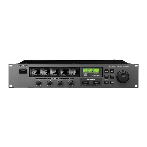
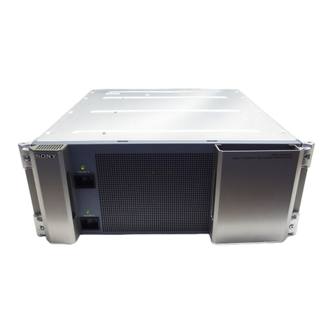
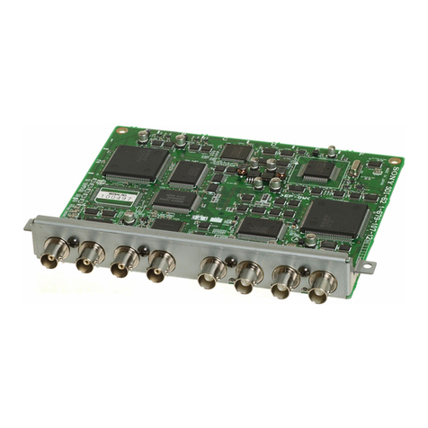
Sony SRP-F700 User manual

SONY.
Digital
Audio
Processor
‘SRP-F700
Instruction
Manual
THANK
YOU
FOR
PURCHASING
A
SONY
SRP-F700
DIGITAL,
AUDIO
PROCESSOR.
Before
beginning
use,
read
this
manual
carefully.
Be
sure
to
keep
it
properly
for
future
reference.
©
1997
Sony
Sound
Tec
Corporation
2-344-632-1141
(1
Contents
Warning
Precautions
3.
On
Adjustment
of
Input
Gain
and
Output
Att
4.
Selecting
Mode
5.
Operation
Menu
6.
Block
Diagram
7.
Main
Specifications
8.
External
Dimensions
Optional
SRP-70BK
(DSP
extention
board
kit)
....

WARNING
Notice
for
the
Customers
in
the
United
Kingdom
IMPORTANT
The
wires
in
this
mains
lead
are
coloured
in
accordance
with
the
following
code:
Blue
:
Neutral
Brown:
Live
As
the
colours
of
the
wires
in
the
mains
lead
of
this
apparatus
may
not
correspond
with
the
coloured
markings
identifying
the
terminals
in
your
plug,
proceed
as
follows:
The
wire
which
is
coloured
blue
must
be
connected
to
the
terminal
which
is
marked
with
the
letter
N
or
coloured
black.
The
wire
which
is
coloured
brown
must
be
connected
to
the
terminal
which
is
marked
with
the
letter
L
or
coloured
red.
Do
not
connect
either
wire
to
the
earth
terminal
in
the
plug
which
is
marked
by
the
letter
E
or
by
the
safety
earth
symbol
Y
or
coloured
green
or
green-and-
yellow.
Afin
d'écarter
tout
risque
d'électrocution,
garder
le
coffret
fermé.
Ne
confier
l'entretien
de
l'appareil
qu'a
un
personnel
qualifié.
Per
evitare
scosse
elettriche,
non
aprire
I'apparecchio.
Per
le
riparazioni
rivolgersi
solo
a
personale
qualificato.
Para
evitar
descargas
eléctricas,
no
abra
la
caja.
En
caso
de
averia,
solicite
los
servicios
de
personal
cualificado
solamente.
To
prevent
fire
or
shock
hazard,
do
not
expose
the
unit
to
rain
or
moisture.
To
avoid
electrical
shock,
do
not
open
the
cabinet.
Refer
servicing
to
qualified
personnel
only.
ee
NCRIIO)N
RISK
OF
ELECTRIC
SHOCK
DO
NOT
OPEN
CAUTION:
TO
REDUCE
THE
RISK
OF
ELECTRIC
SHOCK,
DO
NOT
REMOVE
COVER
(OR
BACK).
NO
USER-SERVICEABLE
PARTS
INSIDE.
REFER
SERVICING
TO
QUALIFIED
SERVICE
PERSONNEL.
This
symbol
is
intended
to
alert
the
user
to
the
presence
of
uninsulated
"dangerous
voltage"
within
the
product's
enclosure
that
may
be
of
sufficient
magnitude
to
constitute
a
risk
of
electric
shock
to
persons.
This
symbol
is
intended
to
alert
the
user
to
the
presence
of
important
operating
and
maintenance
(servicing)
instructions
in
the
literature
accompanying
the
appliance.
*The
location
of
the
marking
is
on
the
top
enclosure.

PRECAUTIONS
On
safety
(Refer
to
the
supplied
"WARNING".)
e
Should
any
liquid
or
solid
object
fall
into
the
cabinet,
unplug
the
unit
and
have
it
checked
by
qualified
personnel
before
operating
it
any
further.
¢
Unplug
the
unit
from
the
wall
outlet
if
it
is
not
to
be
used
for
an
extended
period
of
time.
To
disconnect
the
cord,
pull
it
out
by
grasping
the
plug.
Never
pull
the
cord
itself.
On
installation
¢
Do
not
install
the
unit
in
a
location
near
heat
sources
such
as
radiators
or
air
ducts,
or
in
a
place
subject
to
direct
sunlight,
excessive
dust,
mechanical
vibration
or
shock.
e
When
mounting
the
unit
on
the
EIA
19-inch
standard
rack,
allow
enough
space
of
1U
or
more
above
this
unit
for
good
ventilation.
On
operation
e
Before
making
program
source
connections,
be
sure
to
turn
the
power
switch
off
and
unplug
the
unit.
e
When
the
unit
is
not
used,
turn
the
power
off
to
conserve
energy
and
to
extend
the
useful
life
of
your
unit.
On
cleaning
the
cabinet
Clean
the
cabinet,
panel
and
controls
with
a
soft
cloth
lightly
moistened
with
mild
detergent
solution.
Do
not
use
any
type
of
abrasive
pad,
scouring
powder
or
solvent
such
as
alcohol
or
benzine.
On
repacking
Do
not
throw
away
the
carton
and
the
packing
material.
It
makes
an
ideal
container
for
transporting
the
unit.
When
shipping
the
unit
for
repair
work
or
to
another
location,
repack
it
as
it
was.
If
you
have
any
questions
or
problems
concerning
your
unit,
consult
your
nearest
Sony
dealer.

1.
OUTLINE
The
SRP-F700
digital
audio
processor
is
designed
for
use
with
various
acoustic
systems
installed
in
concert
halls,
multi-purpose
halls,
banquet
rooms,
etc.
The
device
incorporates
two
channels
of
1-input/4-output
processing
systems
to
process
stereo
signals
alone.
Built-in
20-bit,
96
KHz
sampling
A/D and
D/A
converter
.
The
A/D
and
a
D/A
converter
with
96
kHz
sampling
frequency
and
20-bit
quantization
incorporated
produce
quality
sounds
faithfully
from
original
sounds.
High-speed
digital
signal
processing
Twenty
high-speed
DSPs
by
52-bit
internal
computation
corresponding
to
96
kHz
sampling
are
mounted
(at
standard).
Double-
and
quadruple-precision
computation
is
applied
in
the
critical
parts
of
the
digital
signal
processing
unit
of
the
device
to
enhance
computation
accuracy.
This
is
one
of
the
major
features
of
the
device
for
ensuring
high
sound
quality.
The
digital
signal
processing
unit
incorporates
all
the
functions
required
for
sound
field
control,
including
graphic
equalizer,
parametric
equalizer,
notch
filter,
delay,
crossover
network
filter,
limiter/compressor,
and
phase
switcher.
Five
modes,
each
with
a
different
combination
of
processing
(algorithm),
are
available.
The
user
can
choose
the
most
suitable
one
for
sound
field
control
according
to
the
actual
conditions
of
use.
Microcomputer
controlled
analog
sound
volume
control
A
0
to
—-20
dB
analog
sound
volume
control
is
provided
for
each
of
the
eight
outputs.
The
sound
volume
controls
are
located
in
the
analog
signal
unit
after
D/A
converter
so
that
no
sound
deterioration
results
from
bit
loss,
which
occurs
when
the
level
is
controlled
in
the
digital
signal
process.
The
position
(angle)
of
the
eight
sound
volume
controls
are
individually
controlled
by
a
microcomputer.
The
sound
volume
can
be
set
by
the
instructions
from
the
microcomputer
via
motor
drive.
The
sound
volume
control
position
can
be
stored
and
recalled
by
the
program
store
function
described
later.
Up
to
100
programs
can
be
stored
A
maximum
of
20
parameter
setting
conditions
(programs)
can
be
stored
in
each
of
the
five
modes.
The
user
can
recall
the
optimum
program
according
to
the
conditions
of
use.
Easy
to
operate
With
digital
equipment,
it
is
generally
difficult
to
change
parameters,
and
complicated
procedures
are
involved.
The
SRP-F700
device
simplifies
the
parameter
setting
procedure
with
10
function
keys,
four
parameter
knobs
and
a
large-sized
liquid
crystal
display.
To
set
the
parametric
equalizer,
for
example,
three
parameters
of
frequency,
Q,
and
level
are
controlled
by
respective
knobs
just
like
in
an
analog
system.
The
characteristics
are
graphically
shown
on
the
large-sized
liquid
crystal
display
on
a
real
time
basis
as
the
user
changes
the
parameters.
The
user
can
thus
set
the
sound
field
while
listening
to
the
sound
and
watching
the
change
of
the
sound
on
the
graph
on
the
display.
External
control
terminal
provided
The
user
can
recall
programs
stored
in
the
memory
using
MIDI
and
parallel
remote
terminals.
In
addition
to
recalling
programs,
the
user
can
remotely
control
and
change
the
parameters
by
connecting
a
personal
computer
via
the
RS-422A
terminal
(control
via
the
RS-422A
terminal
is
an
optional
specification).

2.
CONTROLS
AND
FUNCTIONS
en,
Jeue
PI
P2
P3
Pa
os}
O
OO
O
@
POWER
Switch
The
internal
condition
is
stored
in
the
memory
for
approximately
six
months
when
the
power
is
turned
OFF.
When
the
user
turns
the
device
ON,
the
previous
condition
returns
automatically
(unless
the
user
changes
the
MODE
switch
on
the
rear
panel).
Liquid
Crystal
Display
(LCD)
The
user
can
set
the
parameters
while
watching
the
LCD.
The
backlight
can
be
turned
OFF.
The
contrast
is
adjustable.
Refer
to
page
45
for
the
description
of
the
system
menu.
The
functions
of
function
keys
©
and
parameter
knobs
@,
described
in
the
following
paragraphs,
are
always
displayed
at
the
edge
of
the
LCD.
Function
Keys
(F1
to
F10)
The
function
keys
are
used
to
select
a
menu,
select
the
parameter
setting
channels,
etc.
The
function
of
F1
to
F10
keys
will
vary
with
the
OUTPUT
LEVEL
CH
OO
.eaTEA
Oem
0.
Pri
Pre
pri
Pri}
—
—|
>
—s
Jom
cH
ie
a
ie
a
a
ne
ai)
a0
Pry
33
=28
‘
xm
.
Re
Z
Bt
2
fos
4
7
4
‘.
{
—s
si
ps
leo
cr
a
bag
Ro
be
a
2
Tom
=a”
Toms
eo
ose
om
A 8
c
°
DIGITAL
AUDIO
PROCESSOR
SRP-F700
8
menu
displayed
on
the
LCD
screen.
When
the
menu
on
the
display
is
changed,
the
function
of
the
function
keys
also
changes.
The
function
of
a
function
key
is
described
at
the
edge
of
the
LCD
close
to
the
relevant
key.
See
individual
menu
screens
for
details.
Any
key
without
a
display
is
ineffective.
There
will
be
no
response
when
pressed.
©
Parameter
Knobs
(P1
to
P4)
Parameter
knobs
are
mainly
used
for
inputting
parameter
values.
Like
the
function
keys,
parameter
knobs
have
a
different
function
depending
on
what
menu
is
currently
shown
on
the
LCD
screen.
The
current
function
is
displayed
on
the
LCD
screen
close
to
respective
knobs.
See
individual
menu
screens
for
details.
Any
knob
without
a
display
is
ineffective.
There
will
be
no
response
when
turned.
(In
the
main
menu
screen,
for
example,
a
message
reads
“DIGITAL
AUDIO
PROCESSOR
SRP-F700”
on
the
lower
part
of
the
LCD
and
the
parameter
knobs
are
ineffective.)

@
INPUT
GAIN
Knobs
(CH-1,
CH-2)
The
INPUT
GAIN
knob
is
used
to
adjust
the
gain
of
the
input
signals
from
the
input
terminals
at
the
front
stage
of
the
internal
A/D
converter.
The
gain
is
adjustable
in
steps
of
3
dB
up
to
15
dB
at
the
maximum.
The
adjustment
with
this
knob
is
directly
related
to
the
available
head
room
within
the
device.
When
the
input
signals
are
continuously
low,
the
head
room
in
the
A/D
converter
may
be
set
as
small
as
possible
so
that
the
bit
loss
at
the
A/D
converter
is
reduced,
and,
accordingly,
the
actual
resolution
is
enhanced.
For
this
reason,
it
is
recommended
that
the
gain
be
adjusted
according
to
the
level
of
the
input
signals.
The
user
can
adjust
the
gain
while
checking
the
level
with
the
INPUT
level
meter
@
and
the
OVER
indicator.
For
how
to
adjust
the
knobs,
refer
to
page
9.
OUTPUT
ATT
(attenuator)
Knobs
(CH-1,
CH-
2)
The
OUTPUT
ATT
knob
allows
the
user
to
attenuate
the
level
of
the
output
signals
after
D/A
conversion
by
a
maximum
of
15
dB
in
steps
of
3
dB.
The
input
and
output
level
of
the
device
will
be
1:1
when
the
position
of
the
INPUT
GAIN
knob
@
is
matched
to
the
position
of
the
OUTPUT
ATT
knob.
Output
Mute
Switches
(CH-1A,
CH-1B,
CH-
1C,
CH-1D,
CH-2A,
CH-2B,
CH-2C,
CH-2D)
The
Output
Mute
switches
are
used
to
select
ON/
OFF
for
the
mute
of
the
output
channels.
The
state
in
which
the
LED
(green)
of
the
key
lights
up
indicates
the
mute
of
the
output.
The
status
of
the
eight
switches
is
stored
and
recalled
as
a
program
parameter.
It
is
automatically
set
when
the
program
is
recalled.
Output
Level
Knobs
(CH-1A,
CH-1B,
CH-1C,
CH-1D,
CH-2A,
CH-2B,
CH-2C,
CH-2D)
These
are
the
knobs
for
the
level
adjust
dials
for
the
output
channels.
They
can
be
attenuated
from
0
dB
to
a
maximum
of
-20
dB,
allowing,
allowing
the
level
balance
to
be
adjusted
up
to
a
maximum
of
20
dB
between
the
output
channels
relatively.
The
status
of
the
eight
knobs
is
stored
and
recalled
as
a
program
parameter.
It
is
automatically
set
by
the
motor
drive
when
the
program
is
recalled.
©
INPUT
Level
Meters
(CH-1,
CH-2)
The
display
range
of
the
input
signal
level
meter
is
from
-3
dBs
to
+24
dBs.
The
displayed
level
is
equal
to
the
signal
level
of
the
input
terminal
plus
input
gains
determined
by
the
INPUT
GAIN
knob
©.
The
+24
dBs
corresponds
to
the
maximum
input
level
(for
the
A/D
converter).
OUTPUT
Level
Meters
(CH-1A,
CH-1B,
CH-
1C,
CH-1D,
CH-2A,
CH-2B,
CH-2C,
CH-2D)
The
display
range
of
the
output
signal
level
meter
is
from
-21
dBs
to
+6
dBs.
The
level
of
signals
output
from
the
output
terminals
on
the
rear
panel
is
displayed.
(The
level
reflects
the
setting
of
OUTPUT
ATT
knobs
CG,
Output
Mute
switches
@,
and
Output
Level
knobs
@.)
The
display
range
of
the
output
level
meter
is
lower
than
that
of
the
input
level
meter
because
the
level
of
signals
is
reduced
when
they
pass
the
crossover
filter.
Input
OVER
Indicators
(CH-1,
CH-2)
(red)
The
Input
OVER
indicators
will
light
up
when
the
level
of
input
signals
to
the
A/D
converter
is
increased
and
the
waveform
clips.
Decrease
the
input
level
when
the
indicator
lights
up
continuously.
Limiter
Indicators
(CH-1A,
CH-1B,
CH-1C,
CH-1D,
CH-2A, CH-2B,
CH-2C,
CH-2D)
(orange)
These
are
the
limiter/compressor
blocks
for
processing
digital
signals
at
each
channel.
They
light
up
when
the
limiter/compressor
operates
with
the
signals
exceeding
the
preset
threshold
values.
CH-1/CH-2/SYNC
Keys
The
SRP-F700
device
incorporates
two
processing
channels
(stereo),
each
comprising
one
input
and
four
outputs.
These
three
keys
are
used
to
set
signal
processing
parameters
for
CH-1
and
CH-2
respectively,
or
to
set
the
same
parameters
for
both.
Refer
to
page
19
for
details.

@
INPUT
Terminals
(CH-1,
CH-2)
Connected
to
the
output
of
a
mixer,
etc.
The
terminal
is
XLR-3-31
or
equivalent.
Electronic
balancer
circuit
(1:GND,
2:HOT,
3:COLD).
@
OUTPUT
Terminals
(CH-1A,
CH-1B, CH-1C,
CH-1D, CH-2A,
CH-2B,
CH-2C,
CH-2D)
The
final
signal,
after
signal
processing
and
D/A
conversion,
is
output.
The
terminal
is
XLR-3-32
or
equivalent.
Electronic
balancer
circuit
(1:GND,
2:HOT,
3:COLD).
©
MODE
Selector
Switch
The
MODE
selector
switch
is
used
to
select
between
crossover
and
distribution
mode,
which
are
the
basic
distinction
of
the
signal
processing
algorithms
(modes).
The
SRP-F700
device
operates
in
the
mode
which
has
been
selected
when
power
is
turned
on.
The
mode
will
not
change
even
if
the
Mode
selector
switch
is
changed
(unless
you
turn
ON
the
power
again).
Refer
to
page
13
for
mode
switching.
CH
Gl
a
ee
_—
SOUTPUF
ee
ee
1
B
c
i>}
A
8
c
ie}
.
x)
<@
QD
oO
A)
©
QO
©
RS-422A
Terminal
for
External
Control
(D-
sub
9-Pin)
The
device
may
be
externally
controlled
when
this
terminal
is
connected
to
the
RS-422A
terminal
of
a
personal
computer
(optional
specification).
MIDI
Terminal
for
External
Control
MIDI
signals
are
input
from
external
equipment
when
the
device
is
connected
with
commercially
available
MIDI
cables.
Programs
can
be
recalled
with
MIDI
signals.
Refer
to
page
46
for
details.
PARALLEL
REMOTE
Terminal
for
External
Control
(D-sub
25-pin)
Programs
are
recalled
with
a
simple
switch
using
this
terminal.
Refer
to
page
47
for
details.
Power
Cord
Connect
the
Power
cord
to
a
230
VAC
outlet.
Air
Cooling
Fan
Ventilation
Warm
air
is
exhausted
from
here
when
the
device
is
used.
Be
sure
not
to
cover
up
this
opening.

3.
ON
ADJUSTMENT
OF
INPUT
GAIN
AND
OUTPUT
ATT
The
INPUT
GAIN
knob
is
used
to
adjust
the
level
in
the
analog
portion
before
the
A/D
converter.
The
OUTPUT
ATT
knob
is
used
to
adjust
the
level
in
the
analog
portion
after
the
D/A
converter.
They
are
not
interlocked
with
the
mode
and
programs
described
later.
With
these
knobs,
the
user
can
adjust
the
relation
between
the
level
of
the
sound
signals
input
to
the
SRP-F700,
head
room
of
the
SRP-F700,
and
the
output
level
of
the
device
when
it
is
connected
to
other
equipment.
For
digital
audio
equipment
in
general,
the
head
margin
in
the
digital
range
is
related
to
the
actual
resolution
of
digital
sound
signals.
The
smaller
the
head
room,
the
fewer
the
bits
wasted
in
a
finite
bit
length.
Accordingly,
the
sound
quality
is
improved
when
the
head
room
of
the
signals
input
to
the
A/D
converter
is
set
at
the
lowest
possible
level
to
the
extent
that
the
full
scale
is
not
exceeded
at
the
maximum
input
and
there
is
no
clip
in
the
digital
signal
processing.
To
produce
a
good
sound
quality,
the
SRP-F700
device
has
an
INPUT
GAIN
knob
for
adjusting
the
head
room
for
the
signals
input
to
the
A/D
converter
at
the
input
stage.
With
this
knob,
the
user
can
adjust
the
gain
of
the
input
signals
on
the
front
stage
of
the
A/D
converter.
The
user
can
adjust
the
INPUT
GAIN
while
checking
the
head
room
with
the
INPUT
level
meter
and
the
OVER
indicator
on
the
panel.
The
maximum
value
of
the
input
level
meter,
+24
dBs,
is
the
maximum
input
level
of
the
SRP-F700
device.
This
level
meter
does
not
indicate
the
level
of
the
signals
input
to
the
SRP-F700,
but
indicates
the
level
plus
the
input
gain
determined
by
the
INPUT
GAIN
knob
@.
For
example,
when
the
input
level
is
+6
dBs,
and
INPUT
GAIN
knob
is
set
to
3,
the
level
meter
indicates
9
dB
(=
6
dBs
+
3
dB).
The
head
room
in
this
instance
is
15
dB
(=
+24
-9).
The
level
meter
can
not
follow
up
peak
signals
but
can
confirm
the
clip
of
peak
waves
with
the
OVER
indicator.
The
OVER
indicator
indicates
that
the
input
signal
peak
has
clipped,
exceeding
the
maximum
input
level
of
the
D/A
converter.
It
is
necessary
to
decrease
the
input
level
when
the
OVER
indicator
lights
up
continuously.
The
device
has
an
OUTPUT
attenuation
knob
corresponding
to
the
INPUT
GAIN
adjustment.
When
the
gain
of
the
input
signals
is
adjusted
with
the
INPUT
GAIN
knob,
all
the
succeeding
output
signals
will
also
have
a
gain.
To
prevent
this,
the
OUTPUT
ATT
knob
is
set
at
the
same
position
as
the
INPUT
GAIN
so
that
the
output
is
attenuated
by
the
same
GAIN
quantity
used
in
the
input
portion.
By
this,
the
relation
between
the
input
and
output
level
of
the
device
is
kept
at
1:1.
This
knob
is
not
necessarily
used
in
combination
with
the
INPUT
GAIN
knob.
It
may
also
be
used
to
adjust
the
output
level.
The
OUTPUT
level
meter
indicates
the
level
of
the
signals
that
have
passed
the
OUTPUT
attenuation
and
OUTPUT
level.

10
4.
SELECTING
MODE
The
first
step
to
set
the
SRP-F700
for
operation
is
selecting
the
operation
mode
(signal
processing
algorithm).
After
selecting
the
mode,
the
parameters
are
set
(refer
to
page
17
and
after).
This
section
describes
the
signal
processing
algorithm
used
in
each
mode,
and
the
mode
selecting
procedure.
The
SRP-F700
device
has
five
modes,
each
with
a
unique
algorithm
for
processing
digital
signals.
One
mode
should
be
selected
for
use.
The
five
modes
are
grouped
into
two
categories
of
crossover
and
distribution
modes
as
shown
below.
Crossover
modes
Mode
A
Mode
B
(optional)
Mode
C
Mode
D
Distribution
mode
—-—————-——————-
Mode
E
Crossover
Mode
(Modes
A
to
D)
Each
crossover
mode
contains
a
unique
algorithm
for
the
crossover
which
is
used
in
multi-
amplifier
speaker
systems.
Each
of
the
crossover
modes
A
to
D
has
a
unique
way
of
processing
with
the
equalizer
and
crossover
filter.
One
out
of
the
four
modes
is
selected
according
to
the
speaker
system
to
be
used.
(Mode
B
is
only
available
with
the
device
provided
with
the
optional
DSP
board.
Refer
to
page
57
and
the
instruction
manual
for
the
optional
kit
SRP-70BK
for
details.)
Distribution
Mode
(Mode
E)
The
input
signals
are
distributed
to
a
maximum
of
four
systems.
The
equalizer,
delay
and
limiter
processing
is
effected
for
each
output
independently.

Q:0.7,
0.9,
1.2,
3,
4.5,7
LEVEL:
0~+120B
0.5dB
step
LOW
SHELVING
FREQ:20Hz~1kHz
1/30ct
step
LEVEL:
0-+12dB
HIGH
SHELVING
FREQ:
1.25kH2~16kHz
Signal
processing
algorithms
in
each
mode
are
described
below.
MASTER
DELAY
DELAY
TIME:
0-1000msec
imsec
step
r——
CROSSOVER
LOW
CUTFILTER
HIGH
CUT
FILTER
FREQ:
22.4H2~20kHz,
LIMITER
100~1000msec
100msec
step
Mode
A
geasasae
CROSSOVER
-------5
’
'
CHANNEL
Lj]
LOW
CUT
HIGH
CUT
Li
LIMITER
PHASE
A
DELAY
,
FILTER
FILTER
:
:
:
1
.
' t
:
:
CHANNEL
|_#__}
LOW
CUT
HIGH
CUT
L_!
IMITER
HA.
DELAY
:
FILTER
FILTER
,
ENASE
e
MASTER
:
:
DELAY
H
'
.
‘
CHANNEL
|__|
LOW
CUT
HIGH
CUT
[__s
DELAY
;
FILTER
FILTER
'
KMTER
le
¢
:
:
4
H
s
:
CHANNEL
|
3}
LOW
CUT
HIGH
CUT
Lt
’
FILTER
FILTER
:
TES
7
Neiencccesccasdos
Jussssocsses
[———
CROSSOVER")
GRAPHIC
EQ
=
MASTER
DELAY
CHANNEL
DELAY
LOWCUTFILTER
HIGH
CUT
FILTER
LIMITER
PHASE
DELAY
TIME:
DELAY
TIME:
FREQ:
:
NORMAL/REVERSE
0~1000msec
0-30msec
OFF,
20Hz~18kHz]
|22.4H2-20kHz,
0.5,
1,
2.5,
31
Band
(1/3
oct)
tmsec
step
10.4usec
step
1/6oct
step
OFF
10,
20,
50,
100,
1/6oct
step
Q:3,
4.5,
7
TYPE:
TYPE:
LEVEL:
Butterworth
+12
dB
(0.5
step)
—-12dB/oct
~18dB/oct
~24dB/oct
Bessel
~12dB/oct
~18dB/oct
Linkwitz-Riley
—24dB/oct
RELEASE:
~12dB/oct
Linkwitz-Riley
100-1000msec
~24dB/oct
100msec
step
Mode
C
pocce>
CROSSOVER
§-----;
'
‘
CHANNEL
Li}
LOW
CUT
HIGH
CUT
Lit
iimiTer
A
DELAY
|!
|
FILTER
FILTER
|
!
H
H
t
'
’
'
a
iy
1
'
CHANNEL
['_|
LOW
CUT
HIGH
CUT
L!
DELAY
|
+
|
FILTER FILTER
|
'
ee
ieee
5
NOTCH
MASTER
:
:
FILTER
DELAY
:
H
,
t
s
CHANNEL
[_+_}
LOW
CUT
HIGH
CUT
Ls
PARAMETRIC
EQ
DELAY
[1
FILTER
FILTER
[5
F
pnase_|
zs
1 '
EQ1~EQ4
' :
H
H
1
'
CHANNEL
|_|
LOW
CUT
HIGH
CUT
Lt
1/12oct
step
petay
|?!
|
FILTER
FILTER
[2]
UMITER
oe
7
- .
i
PHASE
NORMAL/REVERSE

Mode
D
PARAMETRIC
EQ
1/120ct
step
Q:0.7,
0.9,
1.2,
3,
4.5,7
LEVEL:
0-+12dB
0.5dB
step
LOW
SHELVING
FREQ:20Hz~1kHz
1/30ct
step
LEVEL:
HIGH
SHELVING
FREQ:
1.25kHz~
16kH2
NOTCH
FILTER
No.1~No.12
FREQ:
20Hz~20kHz
1/12oct
step
LEVEL:
0-~-120B
3dB
step
NOTCH
FILTER
CHANNEL
DELAY
MASTER
DELAY
MASTER
DELAY
CHANNEL
DELAY
DELAY
TIME:
0-1000msec
imsec
step
LOW
CUT
FILTER
------CROSSOVER------
HIGH
CUT
FILTER
[77
CROSSOVER
LOW
CUT
FILTER
HIGH
CUT
FILTER
FIR
-24dB/oct)
LIMITER
PHASE
FREQ:
400Hz~18kHz
1/6o0ct
step
NORMAL/REVERSE
40,
20, 50,
100,
200
msec
(TYPE:
FIR
-24dB/oct)
THRESHOLD:
+24—6dB
2dB
step
RATIO:
2:1,
4:1,
10:1,
00:1
RELEASE:
100~1000msec
100msec
step
Mode
E
12
CHANNEL
DELAY
LOW
SHELVING
FREQ:20Hz~1kHz,
HIGH
SHELVING
FREQ:
1.25kHz~
16kKHz
1/30ct
step
LEVEL:
0-412dB
0.50B
step
ATTACK:
0.5,
1,
2.5,
10,
20,
50,
100,
10:1,
20:1
RELEASE:
100~1000msec
100msec
step

A
mode
is
selected
in
two
steps.
Selecting
crossover
or
distribution
mode
First
decide
whether
to
use
the
SRP-F700
as
a
crossover
or
a
distribution
device
in
the
procedure
below.
Before
turning
Power
switch
ON,
set
the
slide
switch
on
the
rear
panel
to
either
CROSSOVER
or
DISTRIBUTION.
Turn
Power
switch
ON.
The
equipment
will
operate
in
the
selected
mode
when
Power
switch
is
turned
ON.
The
mode
can
not
be
changed
to
the
other
even
if
the
switch
setting
is
changed
(unless
the
power
is
turned
ON
again).
Rear
Panel
If
the
distribution
mode
was
selected,
it
means
that
the
device
will
be
used
in
mode
E.
If
the
crossover
mode
was
selected,
select
one
out
of
the
four
modes
A
to
D
as
follows.
Switching
among
the
crossover
modes
When
using
the
device
in
the
crossover
mode,
the
mode
can
be
selected
from
modes
A
to
D.
Immediately
after
the
mode
is
changed
from
the
distribution
to
the
crossover
mode
and
the
power
is
turned
ON,
the
mode
select
menu
described
paragraph
2
below
will
be
displayed.
1
Press
SYSTEM
(F10)
key
on
the
main
menu
to
display
the
system
menu.
SYSTEM
MEMLI
:NODE
sLCD
:MIDI
SETUP
:PARALELL
SETUP
*
ILOCK
13

14
2
Press
MODE
(F1)
key
to
display
the
mode
select
menu.
SySTEM
MENU
current
nope
[A]
%
SELECTED
MODE
Select
new
mode.
then
Press
[EXEC
:Félkey.
3
Select
the
desired
mode
with
the
parameter
knob
(P2),
and
press
EXEC
(F6)
key
to
set
the
selection.
Reference
e
When
the
mode
is
switched
in
the
above
procedure,
the
programs,
if
any,
stored
for
that
mode
will
be
displayed
on
the
screen
for
your
selection.
e
When
no
programs
are
stored
for
the
newly
selected
mode,
the
internal
initial
program
will
be
used.
A
confirmation
message,
““You’l]l
use
preset
parameter.
(Press
[F6]),”
will
be
displayed
on
the
LCD.
Press
the
EXEC
(F6)
key
once
again.

5.
OPERATION
MENU
The
following
menus
are
available
for
setting
various
parameters.
Main
menu
System
menu
MODE
|
LCD
MIDI
PARALELL
RS-422
LOCK/UNLOCK
Program
menu
.
RECALL
STORE
NAME
READ
ONLY
DELETE
GEQ
setting
menu
(Modes
A,
B)
Modes
C,
D
[F2]to[F5]
Modes
E
Notch
filter
setting
menu
PEQ
setting
menu
Master
delay
setting
menu
Modes
A,
B,
C,
D
Modes
E
Crossover
seiting
menu
(Modes
A,
B,
C,
D)
Channel
delay
setting
menu
|
Limiter
setting
menu
(Modes
A,
B,
C,
D,
E)
Phase
setting
menu
(Modes
A,
B,
C,
D)
15

16
The
following
LCD
screen
state
is
called
the
main
menu
(screen).
eae
LIMITER.
PHASE
DIGITAL
AUDIO
PROCESSOR
SRP-F700
e
The
middle
window
displays
the
mode,
program
number,
and
program
name
currently
used
at
the
very
top.
(For
details
of
the
program,
refer
to
page
36.)
The
window
shows
the
signal
processing
algorithm
of
the
mode
used.
e
Parameters
other
than
MUTE
and
output
level
can
not
be
set
at
the
main
menu.
Pressing
the
F1
to
F10
function
keys
of
the
main
menu
will
display
the
parameter
setting
menu
for
each
processing
block
for
parameter
to
be
set.
For
details
of
the
parameter
setting
menu,
refer
to
pages
17
to
19.
e
To
store,
recall
a
program,
etc.,
press
the
PROGRAM
(F9)
key
to
display
the
program
menu
(common
to
all
modes).
For
details
of
the
program
menu,
refer
to
page
36.
e
Pressing
the
SYSTEM
(F10)
key
will
display
the
system
menu
for
the
SRP-F700.
This
is
used
to
set
items
other
than
those
related
to
program
setting
such
as
changing
the
mode,
adjusting
the
LCD
brightness
and
contrast,
setting
external
control,
etc.
(common
to
all
modes).
For
details
of
the
system
menu,
refer
to
page
44.
Reference
Parameter
settings
set
in
relation
to
signal
processing
is
called
“PROGRAM”.
This
means
that
when
the
SRP-F700
is
used,
it
is
operated
by
a
certain
program
in
a
certain
mode.
Up
to
20
programs
can
be
stored
in
the
unit
by
mode
and
are
recalled
later.
For
details
on
storing
and
recalling
programs,
refer
to
page
38.

ee
Parameter
setting
menus
can
be
set
from
the
main
menu
to
perform
settings
at
the
following
menus.
Types
of
parameter
setting
menus
©
GEQ
setting
menu
(Modes
A)
........sccccsesessesesestssesseeseeneesseeeesesesaecnscsseneennenees
See
page
20.
e
PEQ
setting
menu
(Modes
C,
D,
E)
.......s.cscssssssscssssesorseeseseeesenstecsesseeessaeseeees
See
page
21.
e
Notch
filter
setting
menu
(Modes
C,
D)
......seccccssssecesereesensesssseseeceseeenseseeaes
See
page
24.
e
Master
delay
setting
menu
(Modes
A,
B,
C,
D)
ou....cescsscesseeteseeeeeeseeeeseees
See
page
25.
e
Channel
delay
setting
menu
(Modes
A,
B, C,
D)/(Modes
EB)
............6
See
page
26,
27.
©
Crossover
setting
menu
(Modes
A,
B,
C)/(Modes
D)
........cescessessesererees
See
page
28,
32.
e
Limiter
setting
menu
(Common
to
all
MENUS)
«0...
ccscceseeeeeeeeeeeeeeseesesetensnees
See
page
33.
e
Phase
setting
menu
(Modes
A,
B,
C,
D)
.......ccceesesssssessenetenseseereseneseesteeneasaees
See
page
34.
©
MUTE
setting
(Regardless
of
the
MOdE)
.........ccsccesseeeseseeteeeseseeeeeseeeseeses
See
page
35.
e
OUTPUT
level
adjustment
(Regardless
of
the
MOde)
...........:cseeeresseeeees
See
page
35.
17

18
The
SRP-F700
has
2
channels
(stereo)
of
1
IN/4
OUT
signal
processing
functions.
Using
the
3
keys-CH-1/CH-2/SYNC,
the
processing
of
CH-1
or
CH-2
can
be
made
the
same
or
changed.
CH-1,
CH-2,
and
SYNC
keys
can
be
used
when
a
certain
parameter
setting
menu
is
displayed.
These
will
not
function
at
the
main
menu.
SYNC
setting
(All
CH-1,
CH-2,
and
SYNC
LEDs
are
lit.)
The
SYNC
setting
will
set
(change)
all
parameters
of
CH-1
and
CH-2
at
a
time
by
controlling
a
parameter
setting
operation
once.
The
LED
of
the
key
will
be
lit,
and
both
CH-1
and
CH-2
will
be
high-lighted
at
the
parameter
setting
screen.
CH-1
CH-2
SYNC
NEZIL
INEZ]
INEZ
Individual
CH
setting
(Either
CH-1
or
CH-2
LED
is
lit,
and
SYNC
LED
is
OFF.)
It
is
possible
to
set
(change)
only
the
CH-1
(CH-2)
parameter.
When
the
CH-1
(CH-2)
key
is
pressed,
only
the
CH-1
(CH-2)
key
LED
will
light
up,
and
the
parameter
setting
of
that
channel
will
be
displayed.
Parameters
displayed
on
the
LCD
screen
indicate
the
channel
value
being
set.
The
channel
being
set
will
be
highlighted
on
the
screen.
CH-1
CH-2
SYNC
CH-1
CH-2
SYNC
ES
Lele]
(o}
eG
Le)
When
switched
to
the
individual
CH
setting,
ali
parameters
of
all
blocks
in
that
program
will
be
set
for
each
channel.

Individual
CH
setting
from
SYNC
setting
When
switched
to
the
individual
CH
setting
after
SYNC
setting
by
pressing
the
CH
key,
either
CH
can
be
changed
according
to
the
SYNC
setting
state.
When
switched
to
the
individual
CH
setting,
after
this,
all
parameters
of
all
blocks
in
that
program
will
be
set
for
each
channel.
It
is
recommended
that
the
common
settings
for
CH-1
and
CH-2
be
set
by
the
SYNC
setting,
followed
by
other
settings
for
each
channel
by
individual
CH
setting.
Returning
to
the
SYNC
state
from
the
individual
CH
setting
state.
When
there
is
no
need
to
set
the
individual
CH
setting,
the
SYNC
setting
can
be
set
as
follows.
1
To
define
the
current
CH-1
setting,
press
the
CH-1
key
to
set
the
CH-1
state.
(Press
the
CH-2
key
in
the
case
of
CH-2.)
2
Press
the
SYNC
key
once.
The
LED
of
the
selected
channel
(CH-1
or
CH-2)
will
light
up.
The
SYNC
key
LED
will
blink
for
confirmation.
3
Press
the
SYNC
key
for
more
than
two
seconds.
The
parameters
will
be
copied,
and
ali
parameters
of
CH-1
or
CH-2
will
be
set
to
the
same
values.
All
CH-1, CH-2,
and
SYNC
key
LEDs
will
light
up
and
the
SYNC
state
will
be
set.
CH-1
CH-2
SYNC
CH-1
CH-2
SYNC
NIZ
NIZ
NIZ|
INIA]
INEZ
SLES
>
BSE
esS
nich2]
—
Rm
(In
this
example,
all
parameters
of
CH-1
are
copied
to
CH-2,
and
the
SYNC
state
will
be
set.)
Reference
When
keys
other
than
the
SYNC
key
is
pressed
while
the
SYNC
key
LED
is
blinking,
the
operation
to
switch
to
SYNC
will
be
canceled.
If
SYNC
is
not
pressed
for
10
seconds
after
blinking
starts,
the
operation
to
switch
to
SYNC
will
be
canceled.
19

20
Used
for
setting
1/3
oct
step,
31
bands
graphic
equalizer.
By
mounting
the
optional
SRP-70BK,
mode
B
(121
bands)
can
be
used.
Functions
of
parameter
setting
knobs
Other
key
functions
FREQ
(P1)
:
Selectsafrequency
;
20
Hz
to
20
kHz
1/3
oct
steps,
31
bands
Q
(P2)
:
SetsQ
;
3,
4.5,
7
(mode
A)
LEVEL
(P3)
:
Sets
a
level
;
£12
dB,
0.5
dB
steps
©
Rotate
the
FREQ
(P1)
and
select
the
frequency
point
to
set
the
level.
The
frequency
being
selected
will
be
displayed
in
the
parameter
function
display
area,
and
a
vertical
line
will
be
displayed
on
the
middle
graph.
e
Set
the
frequency
level
selected
with
FREQ
(P1)
using
LEVEL
(P3).
e
Select
the
31
bands
Q
comprising
GEQ
using
Q
(P2).
The
larger
Q
is,
the
narrower
the
frequency
band
width
to
be
boosted
(or
cut)
in
each
band.
Q
is
not
only
set
for
the
band
selected
with
FREQ
(P1),
but
for
all
31
bands
at
a
time.
FLAT
(F1)
Pressing
the
FLAT
key
for
more
than
2
seconds
will
return
all
bands
to
0
dB.
ON/OFF
(F6/F7)
The
ON/OFF
(F6/F7)
keys
are
used
to
set
the
GEQ
function
ON/OFF.
When
ON
(F6)
is
pressed,
the
GEQ
function
being
set
operates.
When
OFF
(F7)
is
pressed,
the
signal
will
pass
through
the
processing
block
without
the
GEQ
function
operating.
Even
when
set
to
OFF,
parameter
settings
will
be
preserved,
and
settings
can
be
performed
while
viewing
parameter
values.
EXIT
(F10)
Press
the
EXIT
(F10)
key
to
return
to
the
main
menu
from
the
GEQ
setting
menu.

Used
to
set
the
4-band
peaking
filter,
LOW
shelving
filter,
and
HIGH
shelving
filter
to
set
equalizing.
Set
the
respective
screen
for
the
4
output
channels
in
mode
E.
Functions
of
function
keys
and
parameter
setting
knobs
used
EQ1
(F1)
:
Sets
EQ1.
EQ2
(F2)
:
Sets
EQ2.
EQ1
(F3)
:
Sets
EQ3.
EQ2
(F4)
:
Sets
EQ4.
EQL
(F8)
:
Sets
the
LOW
SHELVING
filter.
EQH
(F9)
:
Sets
the
HIGH
SHELVING
filter.
FREQ
(P1)
:
Sets
the
center
frequency
(20
Hz
to
20
kHz,
1/12
oct
steps)
Q
(P2)
:
Sets
Q
(0.7,
0.9,
1.2,
3,
4.5,
7
(6
types))
LEVEL
(P3)
:
Sets
level
(+12
dB,
0.5
dB
steps)
Selecting
the
filter
to
be
set
First
select
EQ
to
be
set
using
the
F1
to
F4,
F8
and
F9
keys.
After
selecting
EQ
to
be
set,
set
parameters
using
the
P2,
P3,
P4
knobs.
(Example
of
screen
where
LOW
shelving
is
being
set)
Table of contents
Other Sony Computer Hardware manuals

Sony
Sony DSBK-210 User manual

Sony
Sony IFB-12 User manual

Sony
Sony BRBK-301 User manual

Sony
Sony BPU4000 User manual

Sony
Sony PCWA-C700 - Wireless Lan Dual Pc Card Datasheet

Sony
Sony SDP-E800 User manual

Sony
Sony BKDS-2530 User manual

Sony
Sony BKPF-L752 User manual

Sony
Sony HFBK-SD1 User manual

Sony
Sony PDBK-201 Quick start guide

Sony
Sony UPA-D3 User manual

Sony
Sony MPE-200 User manual
Sony
Sony BKLE-103PCI User manual

Sony
Sony BRBK-MF1 User manual

Sony
Sony PCWA-C700 - Wireless Lan Dual Pc Card User manual
Sony
Sony PCM-F1 User manual

Sony
Sony BKM-101C User manual

Sony
Sony PCWA-C800S Read This First Quick start guide

Sony
Sony PCWA-C100 User manual

Sony
Sony Vaio PCWA-C700 User manual