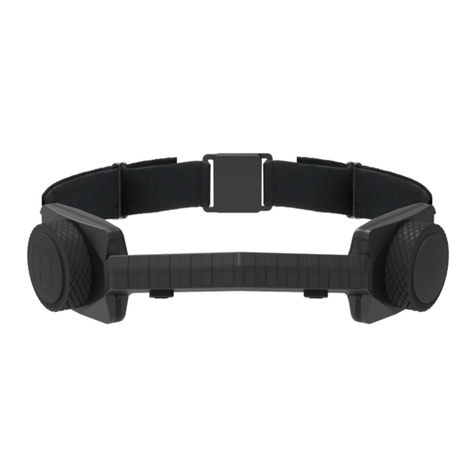
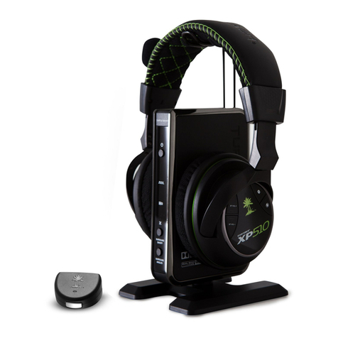
Sony MDR-XB950B1 User manual

SERVICE MANUAL
Sony Video & Sound Products Inc.
9-896-371-01
2017A33-1
© 2017.01
MDR-XB950B1
SPECIFICATIONS
WIRELESS STEREO HEADSET
US Model
Canadian Model
AEP Model
UK Model
E Model
Australian Model
Chinese Model
Ver. 1.0 2017.01
CAUTION
Danger of explosion if battery is incorrectly replaced.
Replace only with the same or equivalent type.
General
Communication system: BLUETOOTH
Specication version 4.1
Output: BLUETOOTH Specication Power
Class 2
Maximum communication range: Line of
sight approx. 10 m (30 ft)1)
Frequency band: 2.4 GHz band (2.4000 GHz
(CH)
- 2.4835 GHz)
Wireless stereo headset
Power source:
DC 3.7 V:Built-in lithium-ion
rechargeable battery
DC 5 V: When charged using USB
Mass: Approx.280 g (10 oz)
Operating temperature:
Usage hours:
Rated power consumption: 1.5 W (Except US, CND)
When connecting via the BLUETOOTH
0 °C to 40 °C (32 °F to 104 °F)
(Except RU, E, IND, AUS)
5 °C to 35 °C (41 °F to 95 °F) (RU, E, IND, AUS)
device
Music playback time: Max. 18 hours
Communication time: Max. 18 hours
Standby time: Max. 200 hours
When connecting via the headphone
cable with the unit turned on:
Max. 18 hours
Note: Usage hours may be shorter
depending on the Codec and the
conditions of use.
Charging time:
Approx. 4 hours
About 6 hours of continuous
communications is possible after 1 hour
charging.
Note: Charging and usage hours may
be dierent depending on the
conditions of use.
95 °F)
Charging temperature: 5 °C to 35 °C (41 °F to
Receiver
Type: Closed, Dynamic
Driver unit: 40 mm
Frequency response: 3 Hz - 28,000 Hz
Impedance:
32 Ω (1 kHz) (when using the supplied
headphone cable) (Except AEP, UK)
38 Ω (1 kHz) (when using the supplied
headphone cable) (AEP, UK)
Sensitivity:
105 dB/mW (when using the supplied
headphone cable) (Except AEP, UK)
97 dB/mW (when using the supplied
headphone cable) (AEP, UK)
50 Hz - 8,000 Hz
Microphone
Type: Electret condenser
Directivity: Omni directional
Eective frequency range:
System requirements
for battery charge
using USB
Personal Computer with pre-installed with
any of the following operating systems and
USB port:
Operating Systems
(when using Windows)
Windows®®
10 Pro
Windows®®
8.1 Pro
Windows®®
8 Pro
Windows®7
8 / Windows
8.1 / Windows
10 Home / Windows
Home Basic / Home Premium /
Professional / Ultimate
(when using Mac)
Mac OS X (version.10.8 or later)
Design and specications are subject to
change without notice.
T
he Bluetooth® word mark and logos are
registered trademarks owned by Bluetooth
SIG, Inc.and any use of such marks by Sony
Corporation is under license.
T
he N-Mark is a trademark or registered
trademark of NFC Forum,Inc. in the United
States and in other countries.
Microsoft, Windows and Windows Vista are
registered trademarks or trademarks of
Microsoft Corporation in the United States
and/or other countries.
Mac and Mac OS are trademarks of Apple
Inc., registered in the U.S. and other
countries.
iPhone and iPod touch are trademark of
Apple Inc., registered in the U.S. and other
countries.
“Made for iPod” and “Made for iPhone” mean
that an electronic accessory has been
designed to connect specically to iPod or
iPhone, respectively, and has been certied
by the developer to meet Apple performance
standards. Apple is not responsible for the
operation of this device or its compliance
with safety and regulatory standards. Please
note that the use of this accessory with iPod
or iPhone may aect wireless performance.
Qualcomm® is a trademark of Qualcomm
Incorporated, registered in the United States
and other countries, used with permission.
Qualcomm aptX™ audio is a trademark of
Qualcomm Technologies International, Ltd.,
registered in the United States and other
countries, used with permission.
Android™ is a trademark of Google Inc.
Other trademarks and trade names are those
of their respective owners.
Modulation method: FHSS (Except CH)
Compatible BLUETOOTH proles2):
A2DP (Advanced Audio Distribution
Prole)
AVRCP (Audio Video Remote Control
Prole)
HFP (Hands-free Prole)
HSP (Headset Prole)
Supported Codec3):SBC4) , AAC5) , aptX
Supported content protection method:
SCMS-T
Transmission range (A2DP):
20 Hz - 20,000 Hz (Sampling frequency
44.1 kHz)
Included items:
Wireless stereo headset (1)
Headphone cable (approx.1.2 m
(47 1/4 in.)) (1)
Micro-USB cable (approx. 50 cm
(19 3/4 in.)) (1)
Reference Guide (1)
Operating Instructions (1)
Other documents (1 set)
(US, CND, AEP, UK, CH, LA only)
1) The actual range will vary depending on
factors such as obstacles between
devices, magnetic elds around a
microwave oven, static electricity,
reception sensitivity, antenna’s
performance, operating system, software
application, etc.
2) BLUETOOTH standard proles indicate the
purpose of BLUETOOTH communications
between devices.
3) Codec: Audio signal compression and
conversion format
4) Subband Codec
5) Advanced Audio Coding
柵䋫剧♘濕3511!NI{!.!!
3594/6!NI{
⌵⭨∃䋫濕Ŭ!31!eCn濃FJSQ濄

MDR-XB950B1
2
SECTION 1
SERVICING NOTES
DESTINATION ABBREVIATIONS
The following abbreviations for model destinations are used in this
service manual.
• Abbreviations
AEP : European, Eastern Europe, CIS area (Moldova) and Mid-
dle Eastern area (Israel) models
AUS : Australian and New Zealand models
CH : Chinese model
CND : Canadian model
IND : Indian model
LA : Latin American model
RU : CIS area (Except for Moldova) model
COLOR VARIATIONS
(B) Black : All models
(L) Blue : Except AEP, UK, IND models
(R) Red : Except AEP, UK, IND models
CHECKING METHOD OF THE SERIAL NUMBER
The serial number of this unit can be checked by removing the ear
pad on the left unit.
Refer to the following figure.
Serial number
label
Earpad
NOTES FOR REPAIR OF BOARDS
When boards installed in this unit are defective, it is replaced by
the board.
Replace the complete mounted board or the whole parts including
the applicable board.
NOTE FOR REPLACING OF MAIN BOARD OR NFC
BOARD
It is always necessary for the MAIN board and the NFC board to
be used in pairs.
Therefore, when replacing the MAIN board or the NFC board, be
sure to replace both parts simultaneously.
Among the repair parts, since the MAIN board and the NFC board
adhered to the right housing are supplied as one unit, when replac-
ing the right housing, replace the MAIN board simultaneously.
HOUSING (R), SV ASSY
The NFC board is mounted
inside the right housing.
NFC board
The MAIN board is
mounted inside the
left housing. 6HUYLFHSDUWV
RESET METHOD
When resetting this unit, operate by following procedure.
Note: Even if this work is performed, device pairing information is not
deleted.
Procedure:
1. Connect this unit to a booted computer using the supplied mi-
cro-USB cable.
2. Press the [1] and [BASS EFFECT] buttons simultaneously.
3. This unit be reset.
Connection:
[1] button
[BASS EFFECT]
button
INITIALIZING METHOD
After completion of repairs, be sure to perform the following pro-
cedure to initialize the unit.
Note 1: When this work is performed, all device pairing information is
deleted and settings return to factory defaults.
Procedure:
1. Check that the micro-USB cable is not connected to this unit,
and turn off the power.
Note 2: If already power is turned off, check the micro-USB cable is not
connected, proceed to step 2.
2. Press and hold the [1] button on the left channel side and the
[NX/] button on the right channel side simultaneously for
7 seconds or longer.
3. The left channel side lamp (blue) flashes 4 times and the set-
tings return to factory defaults.
(Blue)
Note 3: When this unit is initialized, it might not be able to connect to
iPhone or PC.
In that case, delete the registration of this unit on iPhone or PC,
register the device again.
The SERVICING NOTES contains important information for servicing. Be sure to read this section before repairing the unit.

MDR-XB950B1
3
SECTION 2
DISASSEMBLY
• This set can be disassembled in the order shown below.
2-1. DISASSEMBLY FLOW
Note: Follow the disassembly procedure in the numerical order given.
2-2. EAR PAD
2-5. HOUSING (L) ASSY (L-ch)
(Page 6)
2-9. HOUSING (R) ASSY (R-ch)
(Page 8)
SET
2-2. EAR PAD
(Page 3)
2-3. FRONT PLATE (L) ASSY (DR1) (L-ch)
(Page 4)
2-4. MAIN BOARD,
MICROPHONE (MIC1) (L-ch)
(Page 5)
2-7. BATT BOARD (R-ch)
(Page 7)
2-6. FRONT PLATE (R) ASSY (DR2) (R-ch)
(Page 6)
2-8. BATTERY ASSY (BAT1) (R-ch)
(Page 8)
–L-ch –
1ear pad
1Align the positions of the protrusion
on the inner side of the housing groove
and the notch of the ear pad.
protrusion notch
Note 2: Be careful not to insert any foreign objects. Also, be careful because metal
objects will be attracted to the driver if they are near the driver.
+RZWRLQVWDOOWKHHDUSDGV
2Press the notch portion
with your fingers.
3Press the hem of the ear pad into
the groove while moving the ear pad
in the direction of the arrow with
your fingers.
Note 1: L-ch and R-ch can be similarly disassembled.

MDR-XB950B1
4
2-3. FRONT PLATE (L) ASSY (DR1) (L-ch)
2Remove the front plate (L) assy
in the direction of the arrow.
–L-ch –
MAIN board
3Remove the
solder.
[green]
[green]
3Remove the
solder.
[natural]
[natural]
5front plate (L) assy (DR1)
driver
:LUHVHWWLQJ
to front plate (L) assy (DR1)
Driver wire
Note 2: When installing the front plate (L) assy (DR1),
arrange the driver wire into this portion.
1four tapping screws (B2)
Note 1: Be careful not to let the
removed screws stick to
the magnet of the driver.
4serial No. label

MDR-XB950B1
5
2-4. MAIN BOARD, MICROPHONE (MIC1) (L-ch)
–L-ch –
5Remove the MAIN board
in the direction of the arrow.
[black]
[red]
1Remove the solder.
[black]
:LUH VHWWLQJ
MAIN board
microphone wire
relay cable
1Remove the solder.
[red]
3light guide plate
3light guide plate
2Remove seven solders.
6MAIN board
8microphone
(MIC1)
7filament tape
(sub material)
4two tapping screws
(B1.7)
[natural]
[black]
[green] [white]
[red]
[green/natural]
[red/natural]
rib
Note 3: Be sure to fix it.
rib
Note 2: If the relay cable is not long enough, it is
not necessary to fix the wires to this rib.
rib
Note 4: Insert the bundle wire
portion into the rib.
0LcURShRQH ZLUH VHWWLQJ
microphone
(MIC1)
filament tape
(sub material)
filament tape
(sub material)
OK NG
screw boss
Pass the microphone wire
beside the screw boss.
The microphone wire is
overlapping the screw boss.
Note 1: The MAIN board cannot replace with single. When replacing
the MAIN board, be sure to replace the NFC board simul-
taneously. (Repair parts are supplied together with parts that
include the MAIN board and NFC board)

MDR-XB950B1
6
2-5. HOUSING (L) ASSY (L-ch)
2-6. FRONT PLATE (R) ASSY (DR2) (R-ch)
4housing (L) assy
1Remove the shaft of hanger block
from the housing (L) assy.
2Remove the shaft of hanger block
from the housing (L) assy.
–L-ch –
Note: When attaching the housing (L) assy to
the hanger block, be sure to attach from
the side with the relay cable first.
3Draw the relay cable out of
the hole in housing (L) assy.
hanger block
hole
4front plate (R) assy
(DR2)
2Remove the front plate (R) assy
in the direction of the arrow.
[red]
[natural]
:LUHVHWWLQJ
–5FK–
BATT board
3Remove the solder.
[red]
3Remove the solder.
[natural]
to front plate (R) assy (DR2)
Note 1: When installing the front plate (R) assy (DR2),
arrange the driver wire into this portion.
1two tapping screws (B2)
Note 2: Be careful not to let the
removed screws stick to
the magnet of the driver.
1two tapping screws (B2)
Note 2: Be careful not to let the
removed screws stick to
the magnet of the driver.
driver
filament tape
(sub material)

MDR-XB950B1
7
2-7. BATT BOARD (R-ch)
6Remove the BATT board block
in the direction of the arrow.
8BATT board
1Remove the solder.
[black]
5HOD\FDEOHVHWWLQJ
–5FK–
BATT board
1Remove the solder.
[red]
3Remove seven solders.
2filament tape
(sub material)
filament tape
(sub material)
guide line
5two tapping screws
(B1.7)
:LUHVHWWLQJ
to head band assy
(HB1)
to NFC board
to battery assy
(BAT1)
[green/natural]
[natural]
[black]
[black]
[black] [red/natural]
[green]
[white]
[red]
[red]
[red]
BATT board
rib
relay cable battery wires
Note 1: Arrange the battery wires
under the relay cable.
4Remove two
solders.
BATT board
JOG lever
JOG lever JOG lever
OK NG
boss
boss
hole
hole
7JOG lever
Note 2: When installing the JOG
lever, align the two bosses
and two holes.
+RZWRLQVWDOOWKH-OGOHYHU
The opposite side
is orifice side.
orifice side

MDR-XB950B1
8
2-8. BATTERY ASSY (BAT1) (R-ch)
2-9. HOUSING (R) ASSY (R-ch)
2cover battery assy
1claw
1claw
–R-ch –
:LUHVHWWLQJ
battery assy (BAT1) groove
3Peel off the battery adhesive sheet.
Note 1: The battery adhesive sheet is supplied
with the battery assy (BAT1).
If the battery adhesive sheet remains on
the housing (R) side after removing the
battery assy (BAT1), carefully peel off
the battery adhesive sheet and affix it to
the battery assy (BAT1).
4battery assy (BAT1)
Note 2: When removing the battery assy (BAT1)
from the battery adhesive sheet, the battery
assy (BAT1) cannot be reused.
Be sure to replace them with new parts.
4housing (R) assy
NFC board
1Remove the shaft of hanger block
from the housing (R) assy.
2Remove the shaft of hanger block
from the housing (R) assy.
–R-ch –
hanger block
3Draw the relay cable out of
the hole in housing (R) assy.
Note 2: When attaching the housing (R) assy to
the hanger block, be sure to attach from
the side with the relay cable first.
Note 1: The NFC board cannot replace with single. When replacing
the NFC board, be sure to replace the MAIN board simul-
taneously. (Repair parts are supplied together with parts that
include the MAIN board and NFC board)

9
MDR-XB950B1
SECTION 3
EXPLODED VIEWS
Note:
• -XX and -X mean standardized parts, so
they may have some difference from the
original one.
• Items marked “*” are not stocked since
they are seldom required for routine ser-
vice. Some delay should be anticipated
when ordering these items.
• The mechanical parts with no reference
number in the exploded views are not sup-
plied.
• Color Indication of Appearance Parts Ex-
ample:
KNOB, BALANCE (WHITE) . . . (RED)
Parts Color Cabinet’s Color
3-1. HOUSING (L-ch) SECTION
DR1
3
3
4
41
2
2
2
2
MIC1
5
A
A
–R-ch –
–L-ch –
housing (R-ch), head band section
MAIN board
(included in Ref. No. 56 on page 10)
(See Note)
not supplied
Note: The MAIN board cannot replace with single. When replacing
the MAIN board, be sure to replace the NFC board simultane-
ously. (Repair parts are supplied together with parts that include
the MAIN board and NFC board)
1 4-570-942-01 PAD, EAR (for Black)
1 4-570-942-21 PAD, EAR (for Red)
1 4-570-942-31 PAD, EAR (for Blue)
2 4-537-823-01 SCREW (B2), TAPPING
3 4-537-824-01 SCREW (B1.7), TAPPING
4 4-537-807-01 PLATE, LIGHT GUIDE
5 A-2182-584-A HOUSING (L), SV ASSY (for L-ch)
(Including Button) (for Red)
5 A-2182-589-A HOUSING (L), SV ASSY (for L-ch)
(Including Button) (for Black)
5 A-2182-888-A HOUSING (L), SV ASSY (for L-ch)
(Including Button) (for Blue)
DR1 A-2182-586-A PLATE FRONT (L), SV ASSY (for L-ch)
(Including Driver, Wire) (for Blue, Red)
(US, CND, E, AUS, CH, RU, LA)
DR1 A-2182-593-A PLATE FRONT (L), SV ASSY (for L-ch)
(Including Driver, Wire) (for Black)
(US, CND, E, AUS, CH, RU, IND, LA)
DR1 A-2182-595-A PLATE FRONT (L) (CE), SV ASSY (for L-ch)
(Including Driver, Wire) (for Black) (AEP, UK)
MIC1 1-852-026-11 MICROPHONE (Including Wire)
Ref. No. Part No. Description Remark Ref. No. Part No. Description Remark
• Refer to “COLOR VARIATIONS” on page 2
about color variation of the unit.

10
MDR-XB950B1
3-2. HOUSING (R-ch), HEAD BAND SECTION
B
DR2 51
52
52
52
53
53
55
54
52
56
–R-ch –
–L-ch –
HB1
B
C
C
BAT1
(included in MAIN board on page 9)
(See Note 1)
not supplied
D
D
Note 1: The NFC board cannot replace with single. When replacing
the NFC board, be sure to replace the MAIN board simul-
taneously. (Repair parts are supplied together with parts that
include the MAIN board and NFC board)
Note 2: When removing the battery assy (Ref. No. BAT1) from the
battery adhesive sheet, the battery assy (Ref. No. BAT1) can-
not be reused. Be sure to replace them with new parts.
51 4-570-942-01 PAD, EAR (for Black)
51 4-570-942-21 PAD, EAR (for Red)
51 4-570-942-31 PAD, EAR (for Blue)
52 4-537-823-01 SCREW (B2), TAPPING
53 4-537-824-01 SCREW (B1.7), TAPPING
54 A-2059-684-A COVER BATTERY ASSY
55 A-2167-657-A BATT BOARD, COMPLETE
56 A-2182-585-A HOUSING (R), SV ASSY (for R-ch)
(Including MAIN board, NFC board) (for Red)
(US, CND, E, AUS, CH, RU, LA) (See Note 1)
56 A-2182-591-A HOUSING (R), SV ASSY (for R-ch)
(Including MAIN board, NFC board) (for Black)
(Except AEP, UK) (See Note 1)
56 A-2182-592-A HOUSING (R) (CE), SV ASSY (for R-ch)
(Including MAIN board, NFC board) (for Black)
(AEP, UK) (See Note 1)
56 A-2182-889-A HOUSING (R), SV ASSY (for R-ch)
(Including MAIN board, NFC board) (for Blue)
(US, CND, E, AUS, CH, RU, LA) (See Note 1)
BAT1 A-2182-590-A BATTERY SV ASSY
(Including Adhesive sheet, Label) (Except CH)
(See Note 2)
BAT1 A-2185-355-A BATTERY SV ASSY (CN)
(Including Adhesive sheet, Label) (CH)
(See Note 2)
DR2 A-2182-587-A PLATE FRONT (R), SV ASSY (for R-ch)
(Including Driver, Wire) (for Blue, Red)
(US, CND, E, AUS, CH, RU, LA)
DR2 A-2182-594-A PLATE FRONT (R), SV ASSY (for R-ch)
(Including Driver, Wire) (for Black)
(US, CND, E, AUS, CH, RU, IND, LA)
DR2 A-2182-596-A PLATE FRONT (R) (CE), SV ASSY (for R-ch)
(Including Driver, Wire) (for Black) (AEP, UK)
HB1 A-2167-528-A HEADBAND ASSY (Including Relay cable)
(for Black) (US, CND, LA)
HB1 A-2167-529-A HEADBAND ASSY (Including Relay cable) (for Red)
(US, CND, LA)
HB1 A-2167-530-A HEADBAND ASSY (Including Relay cable)
(for Blue) (US, CND, LA)
HB1 A-2167-634-A HEADBAND ASSY (Including Relay cable)
(for Black) (AEP, UK)
HB1 A-2167-635-A HEADBAND ASSY (Including Relay cable)
(for Black) (E, AUS, RU)
HB1 A-2167-636-A HEADBAND ASSY (Including Relay cable)
(for Red) (E, AUS, RU)
HB1 A-2170-600-A HEADBAND ASSY (Including Relay cable)
(for Blue) (E, AUS, RU)
HB1 A-2170-601-A HEADBAND ASSY (Including Relay cable)
(for Black) (CH)
HB1 A-2170-602-A HEADBAND ASSY (Including Relay cable) (for Red)
(CH)
HB1 A-2170-603-A HEADBAND ASSY (Including Relay cable)
(for Blue) (CH)
HB1 A-2170-604-A HEADBAND ASSY (Including Relay cable)
(for Black) (IND)
Ref. No. Part No. Description Remark Ref. No. Part No. Description Remark

Ref. No. Part No. Description Remark
MDR-XB950B1
1111
SECTION 4
ACCESSORIES
4-689-645-12 MANUAL, INSTRUCTION (Operating Instructions)
4-689-646-11 GUIDE, REFERENCE
(ENGLISH, FRENCH, SPANISH) (US, CND, LA)
4-689-646-23 GUIDE, REFERENCE (SIMPLIFIED CHINESE)
(CH)
4-689-646-33 GUIDE, REFERENCE
(ENGLISH, TRADITIONAL CHINESE, KOREAN,
RUSSIAN, UKRAINIAN) (E, AUS, RU, IND)
4-689-646-41 GUIDE, REFERENCE (ENGLISH, FRENCH,
SPANISH, GERMAN, DUTCH, ITALIAN,
HUNGARIAN, POLISH) (AEP, UK)
4-689-646-51 GUIDE, REFERENCE (BULGARIAN, CZECH,
PORTUGUESE, SLOVAK, ROMANIAN,
SLOVENIAN, GREEK) (AEP, UK)
501 1-848-682-11 CABLE, CONNECTION (USB)
(Micro-USB cable (approx. 50 cm))
502 1-846-746-71 CABLE (WITH PLUG)
(Headphone cable (approx. 1.2 m))
501
502
Headphone cable (approx. 1.2 m) (1)
501
Micro-USB cable (approx. 50 cm) (1)

MDR-XB950B1
REVISION HISTORY
Ver. Date Description of Revision
1.0 2017.01 New
Other manuals for MDR-XB950B1
4
Table of contents
Other Sony Headset manuals

Sony
Sony WI-C300 User manual

Sony
Sony WH-CH720N User manual

Sony
Sony XBA-40iP User manual

Sony
Sony CECHYA-0080 User manual

Sony
Sony MDR-XB55AP User manual

Sony
Sony DR-XB23VP User manual

Sony
Sony WH-CH500 User manual

Sony
Sony DR-BT30Q - Wireless Stereo Headset User manual

Sony
Sony DR-GA200 User manual

Sony
Sony WF-SP700N Reference guide

Sony
Sony WF-1000XM4 User manual

Sony
Sony XBA-2IP User manual

Sony
Sony DR-BT21IK/B - Wireless Transmitter And Bluetooth... User manual

Sony
Sony SP700N User manual

Sony
Sony WH-1000XM2 User manual

Sony
Sony WF-1000X User manual

Sony
Sony MDR-XB950BT User manual

Sony
Sony MDR-XB650BT User manual

Sony
Sony MDR-ZX330BT User manual

Sony
Sony MDR-XB50AP User manual