manuals.online logo
Brands
  1. Home
  2. •
  3. Brands
  4. •
  5. Sony
  6. •
  7. Measuring Instrument
  8. •
  9. Sony BVU-800 User manual

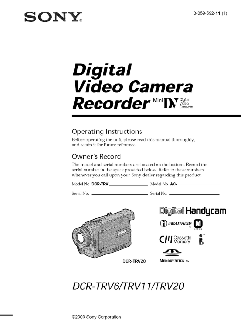
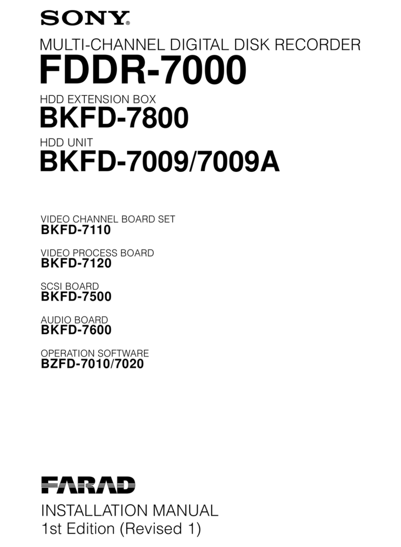
Sony BVU-800 User manual

SONY
V
ID
E
OCASS
E
TT
E
RE
CO
R
D
ER
BVU
-800
®
f
'
σ

σ
°
F
γ
,
σ
Ε
~σ
~

ι
σ
zrn
rr
Π
ΠΥ
.
.,
ε
~
πΠΠ
~
ηΠΠ
~
ή
-matic,
P
rofessional
O
PER
ATIO
N
AND
M
AI
N
T
EN
A
N
C
E
M
A
NU
A
L
6t
h
E
d
ition
(
R
evise
d
15)
Serial
No
.
14751
an
d
H
ig
h
er
TA
BLE
O
F
CO
N
T
EN
TS
1
.
OPERATION
1-1
.
Features
.....................
.
...
. .
1-1
1-2
.

Cassette
Insertion
and
R
e
m
ova
l

....
. .
.
.......

1-2
1-3
.

L
ocat
i
o
n
an
d
Fun
ction
of
Controls

. .
..........

1-4
1-4
.
Recording
....
.
...
.
.
.
.
...
.
..........
1-12
3-3
.

Printed
Circ
ui
t
B
oards

......
.
.
. .
.
.....
.
. .

3-7
3-4
.

Mechanical Operation

.
........
.
.
.
.
.
.
.....

3-7
3-4-1
.

Cassette-
in
/Cassette-o
u
t
O
p
eratio
n

.....
.
.
...

3-7
3-4-2
.

Threading
a
nd
Un
t
h
rea
di
ng
O
p
eration

........

3-9
3-4-3
.

Electrical
T
ap
e
T
e
n
s
i
on D
etecor
.....
.
......

3-11
3-4-4
.

F
W
D
,
RE
V
,
S
HU
TT
LE,
JOG
O
p
erat
i
on

.....
. .

3-12
3-4-5
.

F
.
F
W
D
a
nd
RE
W
O
p
eratio
n
.........
.
. .
. .

3-14
3-5
.

Cassette
Re
m
ova
l
Procedure
w
h
e
n
Normal
E
j
ect
i
on
i s
n
ot Possib
l
e

..............
.
........

3-15
4
.

PER
IODIC
C
HE
C
K
A
N
D
M
AI
N
T
EN
A
N
C
E
4-1
.

Periodic
C
h
ec
k and
M
a in
tenance
Sched
ul
e

........

4-1
4-2
.

System
Co
n
tro
l
O
p
erat
i
on Check

.
.
.
.
.........

4-3
4-2-1
.

Play
Back
,
F
.
F
W
D
,
RE
W
,
S
HU
TT
LE,
J
OG
a
nd
Ρτ
e
το
ll
Fu
nctio
n
Ch
ec
k

.............

4-3
Warni
n
g-T
h
is
e
qu
i
pm
e
n
t
gen
e
r
ates,
u
ses,
a
nd
can
r
a
d
iate
r
a
d
io fr
e
qu
e
n
cy ene
r
gy a
nd
if
not
i
n
stalle
da
nd
used
i
n
acco
rd
-
a
nce
wit
h
t
he
i
n
st r
uctio
n
s
ma
nu
al,
may
ca
u
se
i
n
te
r
fe
r
en
ce
to
r
a
d
io
com
mun
icatio
n
s
.
It
has
b
ee
n
teste
d
a
nd
fo
und
to co
mp
ly
wit
h
t
he
li
m
its
fo
r
α
Class
Α
com
p
uti
n
g
d
evice
pur
s
u
a
n
t
to
S
ub-
p
art
J
of
Part
15
of
F
CC
Ru
les,
w
h
ic
h
a
r
ed
esig
ned
to
provide
reasonable
pr
otectio
n
again
st
suc
h
i
n
te
r
fe
r
en
ce
w
hen
o
p
e
r
ated
in
α
co
m
me
r
cial
e
n
vi
r
o
nm
en
t
.
O
pe
r
atio
n
of
t
h
is
e
qu
ip-
m
en
t
i
nα
r
esi
de
n
tial
a
r
ea
is
li
k
ely
to
ca
u
se
i
n
te
r
fe
r
ence
i
n
w
h
ic
h
case
t
he use
r
at
h
is
own
ex
pen
se
will
b
e
r
equ
i r
e
d
to ta
k
e
w
hateve
r
meas
ur
es
may
be
r
e
qu
i
r
ed
to
co
rr
ect
t
h
e
in-
terference
.
1-5
.
Pl
aybac
k
...
.
. .
. .
...
.......
.
........
1-6
.
E
d
i
ti
ng
............................
1-6-1
.
E
d
i
ti
n
g
w
i
t
h
TwoΒ
VU
-800
Vi
deo
Cassette
Recorders
.........
.
.......
.
......
Blink
of
t
he L
a
mp
s
.
. .
.
.
. .
.....
....
.
How
to
use
t
h
e
Searc
h
Bu
tto
n
.
.
...
.
.
. .
.
.
1-16
4-2-2
.
Record
Fun
ct
i
on
C
hec
k
.
.
.
..........
.
. .
1-19
4-2-3
.
Ed
iti
ng
Fun
ctio
n
C
h
ec
k
....
............
4-3
.
M
a
i
nte
n
ance
after
Re
p
a
i
rs
.................
1-19
4-4
.
Periodic
C
heck an
d
M
a
i
nte
n
ance
Proced
u
re
. .
.
.
.
. .
1-31
4-4-1
.
C
l
ea
nin
g
Procedure
o
ft
h
e
V
id
eo
H
eads
1-31
and
t
heRotary
Erase
H
eads
. .
.
. .
. .
.
. .
.
.
.
4-5
4-6
4-8
4-8
4-11
Q
ui
c
k
Edi
ting
..............
.
.
.
.
1-32
4-4-2
.
C
l
ea
n
in
g
Proced
u
re
o
f
T
ap
e
M
oveme
n
t
Areas
...
.
4-11
Conti
nuou
s
Ed
i
ti
n
g
.............
.
...
1-33
4-4-3
.
H
ea
dD
ega
u
ss in
g
...
.
..........
.
...
.
.
.
4-11
S
p
lit
E
dit
...............
...
.....
1-34
4-4-4
.
C
l
ea
nin
gof S
lip-Ri
ngs
a
nd
Brushes
......
.
...
4-11
Live
E
dit
.......................
1-36
Manual
Editing
. .
. .
....
. .
......
...
.
1-37
5
.
S
ERV
IC
E
I
NF
O
RM
ATIO
N
1-6-2
.
E
d
i
ting
Using
O
ne
Β
VU
-800
V
ideo
Cassette
Recorder
........................
1-38
5-1
.
R
e
m
ova
l
of
Cab
in
et
..................
.
. .
5-1
1-6-3
.
E
d
i
ti
n
g
w
i
t
hα
Co
n
ve
n
t
i
o
na
l
Co
n
tro
l
Uni
t
......
1-39
5-2
.
Re
m
ova
l
o
f
Cassette-up
Compartment
..........
5-2
1-6-4
.
Tim
e
Code
E
d
i
ting
...................
1-40
5-3
.
Sp
ace
Parts
.....
.
.....................
5-2
1-7
.
T
ap
e
Protection
.....
.
.....
.
.
....
. .
...
.
1-42
5-4
.
M
od
ul
e
Extender
......................
5-2
1-8
.
C
l
ea
nin
g
t
h
e
H
ead
.....
.
......
.
. .
. .
.
....
1-42
5-5
.
Ca
u
tion
o
f
Hi
g
h
V
o
l
tage
..................
5-2
1-9
.
Ch
ec
k
R
o
u
ti
n
es
...
.
.
.....
. .
.
.
.
...
.
.
.
.
.
1-43
5-6
.
Mu
t i
ng o
f
T
ape
Beg
inni ng
Sensor
and
1-10
.
Con
n
ect
i
o
n
s
.....
.
.
. .
.
.
.
.
.
...
.
.
......
1-48
T
a
p
e
End
Sensor
......................
5-3
1-11
.
Sp
eci
fi
cat
i
o
n
s
. .
...
.
...
.
. .
.
. .
. . . .
.
....
1-52
5-7
.
Fixture
............................
5-3
1-12
.
R
ep
ac
k
ing for
s
hipm
ent
. . .
...
. .
.
.
.
....
. .
.
1-54
5-8
.
SA
FE
TYC
HE
CK
-O
UT
.....
.
......
.
. .
.
.
. .
5-4
2
.
I
N
STA
LL
ATIO
N
6
.
REPL
AC
EMEN
TO
F
M
A
J
O
R P
A
R
TS
2-1
.
O
p
erat
i
on
Environment
.................. .
2-1 6-1
.
R
e pl
ace
m
en
t
of
D
r
um
A
sse
m
b
l
y
.............
6-1
2-2
.
Installat
i
on
Sp
ace
. .
....................
2-1
6-2
.
Re
pl
ace
m
en
t
of
Upper
Drum
A
sse
m
b
ly
.........
6-1
2-3
.
Operating
V
o
l
tage
......................
2-2 6-3
.
R
e pl
ace
m
en
t
of
T
e
n
s
i
on
D
etector
.............
6-3
2-4
.
Co
n
nect
i
ons
.
.
..
. .
.
.......
.
............
2-3 6-4
.
Re
pl
aceme
n
t
o
f
Motor
.....
.
..............
6-4
2-5
.
Input/Ou
t
pu
t
Signa
l
o
f
t
he
Con
n
ector
..........
2-7
6-4-1
.
R
ep
lace
m
en
t
o
f
R
ee
l
M
otor
..............
6-4
2-6
.
Co
nn
ect
i
on
Connector
....
.
.
...
.
. .
.
. . .
.
. .
2-8
64-2
.
R
ep
lace
m
e
n
t
o
f
Ca
p
sta
n
M
otor
............
6-4
2-7
.
Se
l
ect
Switc
h
Sett
in
g
...........
.
.
.
.
.
. . .
.
2-8
6-4-3
.
R
e
pl
ace
m
e
n
t
o
f
Threading
M
otor
...........
6-5
2-8
.
Rac
k
M
oun
t
i
ng
..................
.
.
. .
.
2-10
6-4-4
.
R
ep
lace
m
e
n
t
of
Cassette-up
A
sse
m
b
ly
's
Motor
...
6-5
2-9
.
Co
n
tro
l
P
a
n
e
l
Uni
t
R
e
m
ova
l
................
2-11
6-5
.
R
ep
lace
m
e
n
t
o
f
t
he
Stationar
y
H
ead
...........
6-6
2-10
.
S
uppli
e
d
A
ccessory
.....................
2-12
6-5-1
.
R
e
pl
ace
m
e
n
t
of
Erase
H
ea
d
..............
6-6
2-11
.
O
p
tio
n
a
l
Accessory
.....................
2-12
6-5-2
.
R
e
pl
ace
m
e
n
t
o
f
T
ime
Code
H
ead
...........
6-6
6-5-3
.
R
e
pl
ace
m
e
n
t
o
f
A
u
d
i
o/C
TLH
ead
...........
6-6
3
.
T
E
C
HN
ICAL
I
NF
O
RM
ATIO
N
6-6
.
Re
p
lace
m
e
n
t
o
f
P
i
n
c
h
Roller
................
6-7
3-1
6-7
.
Re
pl
ace
m
e
n
t
o
f
Brake
B
a
n
d
. .
.
...
.
...
.
...
.
.
6-7
3-1
.
S
p
ec
ifi
cat
i
on
s
.
.
................
.
......
3-2
6-8
.
Re
pl
ace
m
e
n
t
of
t
he
Be
l
t
....
.
. .
.
.....
.
....
6-8
3-2
.
L
ocat
i
on
o
f
M
a
i
n
Parts
....................
6-8-1
.
R
ep
lace
m
e
n
t
o
ft
he Threading
Motor's
Be
l t
. .
. .
.
6-8
3-2-1
.
L
ocation
of
t
h
e
Printed
Circ ui
t
Board
. .
.
.....
3-2
6-9
.
Brush
R
e
p
lace
m
en
t.
.
.
.. .
.
.
.
.
.
...
.
.
.
.
.
. .
6-8
3-2-2
.
L
ocat
i
on
o
ft
h
e
M
echan
i
ca
l
M
a
in
6-10
.
A
d
j
u
st
m
ent
Ite
m
T
ab
l
e
after
Main
Parts
R
ep
l
ace
m
e
n
t
. .
6-10
Pa
r
ts/Co
mp
o
n
ents
..........
.
...
.
.
.
.
.
3-5
7
.
L
I
NK
A
NDD
R
I
VE
SYST
EM
A
L
IG
NMEN
T
9
.
TAPE
RUN
A
L
IG
NMEN
T
7-1
.
Cassette
Retainer
H
eig
h
t
A
d
j
u
st
m
en
t .
...
.
. .
....
7-4 9-1
.
Pi
n
c
h
Roller
Ad
j
u
st
m
e
n
t
.......
...........
9-1
7-2
.
Ree
l
T
ab
l
e
H
eig
h
t
Ad
j
u
st
m
e
n
t
. . . .
.
.
.
...
...
7-4
9-1-1
.
Pinch Lever
Righ
t
A
n
g
l
e
Ad
j
u
st
m
e
n
t
...
......
9-1
7-3
.
EM-1
Board
M
o
un
ti
n
g
Pos
i
t
i
on
Ad
j
u
st
m
e
n
t
.
.
.
.
...
7-5
9-1-2
.
Pi
n
c
h
Roller
Stopper Pos
i
t
i
o
n
Ad
j
u
st
m
e
n
t
......
9-2
7-4
.
Ree
l
M
oto
r
Sh
a ft
S
l
a
n
tness
Ad
j
u
st
m
en
t
.
.
.
.
.
.
...
7-6
9-1-3
.
Pi
n
c
h
Roller
Se
lf
-Alig
nm
en
t
A
d
j
u
st
m
e
n
t
.
.
. .
...
9-3
7-5
.
S
T
e
n
s
i
on
Regulator
Arm
FF
Pos
i
t
i
o
n
Ad
j
u
st
m
ent
...
7-7
9-1-4
.
Pi
n
c
h
Roller
Ze
ni
t
h
A
d
j
u
st
m
e
n
t.........
.
.
.
9-4
7-6
.
Supply
T
en
s
i
on
R
egul ator
Arm
F
W
D
P
os
i
t
i
on
9-1-5
.
Pi
n
c
h
R
oller
A
zimu
t
hAd
j
u
st
m
e
n
t
.........
.
9-4
Ad
j
u
st
m
e
n
t
..................
.
...
.
.
.
7-8
9-1-6
.
Pi
n
c
h
Roller
Preset
A
d
j
u
st
m
en
t ..........
.
.
9-6
7-7
.
Cassette-up
Co
mp
art
m
en
t
A
d
j
u
st
m
e
n
t
.......
.
.
.
7-9 9-2
.
F
W
D
/
REV
T
ape
Run
Ad
j
u
st
m
e
n
t
............
.
9-7
7-7-1
.
IN
Sw
i
tc
h P
os
iti
o
nAd
j
u
st
m
e
n
t
...........
.
7-9
9-2-1
.
T
a
p
e
Run
A
d
j
u
st
m
en
t at
T
h
r
eadi
ng
G
ui
de
(1)
....
9-7
7-7-2
.
D
OW
NSw
i
tc
h P
os
i
ti
on
Ad
j
u
stme
n
t
..........
7-10
9-2-2
.
T
a
pe
W
rin
kl
e
R
e
l
ease
Ad
j
u
st
m
e
n
t
at Pi
nch
Roller
. .
9-8
7-8
.
Sk
ew
So
l
en
oid
M
o
un
ti
n
g
Pos
i
t
i
on
A
d
j
ustmen
t
.....
7-11
9-2-3
.
T
a
pe
RunAd
j
u
st
m
en
t
at
Correction
G
ui
de
(
Α
)
...
9
Α
7-9
.
Supply
T
en
s i
on So
l
e
no
id
M
o
un
ti
n
g
Pos
i
t
i
on
9-2-4
.
T
a
pe
Ru
n
Ad
j
u
st
m
en
t
at
6t
h
G
uid
e
..........
9-10
Ad
j
u
st
m
e
n
t
.........................
7-11
9-2-5
.
T
a
pe
Run
A
d
j
u
st
m
en
t
at
S
G
ui
de
(1)
and
(2)
....
9-11
7-10
.
Threading
Syste
mA
d
j
u
st
m
ent
...............
7-12
9-2-6
.
F
W
D
/
RE
V
T
ap
e
Ru
n Overa
l
l
A
d
j
u
st
m
e
n
t
......
9-12
7-10-1
.
Th
readi
ng Ring Rotat
i
on
A
d
j
u
st
m
e
n
t
.........
7-12
9-2-7
.
S
T
e
n
s
i
on
Regulator
Arm
Pin
Slantness
7-10-2
.
Ri
n
g
Drive
Gear
En
gage
m
e
n
t
Ad
j
u
st
m
en
t
......
7-13
Ad
j
u
stme
n
t
.............
.
.
.
.
......
9-14
7-10-3
.
R
i
ng
Sensor
Pos
i t
i
on
Ad
j
u
st
m
e
n
t
...........
7-13
9-3
.
Video
Tracking
A
d
j
u
st
m
e
n
t
..........
......
9-16
7-10-4
.
Μ
Sto
pp
e r
M
o
un
ti
n
g
Pos
i
t
i
on
Ad
j
ustme
n
t
......
7-14
9-4
.
Erase
H
ead
Z
e
ni
t
h
Ad
j
u
st
m
en
t
........
......
9-18
7-10-5
.
ΤΗ
H
o
l
der
En
d Pos
i
t
i
on
Ad
j
u
st
m
en
t .....
.
...
7-14
9-5
.
Tim
e
Code
H
ead
A
d
j
u
st
m
ent
.......
.
.
......
9-19
7-10-6
.
Th
readi
ng
Slider
EJE
CT
Pos
i
t
i
on
Ad
j
u
st
m
e
n
t
....
7-15
9-5-1
.
Tim
e
Code
H
ead
T
a
p
e-to-
H
ead
Co
n
tact
7-10-7
.
R
e
l
ease
Ca
m
In
stal
l i
n
g
Pos
i
t
i
on
Ad
j
u
st
m
e
n
t
.....
7-16
A
d
j
u
st
m
e
n
t
..................
.....
9-19
7-10-8
.
Ph
oto
Coupler Cover H
eig
h
t
A
d
j
u
stme
n
t
.......
7-16
9-5-2
.
T
i
m
e
Code
H
ead
H
eig
h
t
Ad
j
u
st
m
e
n
t
...
......
9-20
7-10-9
.
5t
h
G
uid
e
O
p
erating
Pos
i
t
i
on
A
d
j
u
st
m
e
n
t
......
7-16
9-5-3
.
T
i
m
e
Code
H
ead
Z
e
ni
t
h
Ad
j
u
st
m
e
n
t
.
.
.
......
9-21
7-10-10
.5t
h
G
ui
de
Unthreading
Pos
i t i
on
A
d
j
ustme
n
t
.....
7-18
9-6
.
A
ud
i
oH
ead
A
d
j
u
st
m
e
n
t
..........
.
..
.
.
. .
.
9-22
7-10-11
.7
En
d
Sensor
Posit
i
on
A
d
j
u
st
m
en
t
..........
7-19
9-6-1
.
Au
d
i
oH
ead
H
e
i
g
h
t
A
d
j
u
st
m
en
t
.......
. .
.
. .
9-22
7-10-12
.
T
ak
e-up
T
e
n
s
i
on
Arm,
Unthreading
Pos
i t i
on
9-6-2
.
A
ud
i
oH
ead
Zen
i
t
h
A
d
j
u
st
m
ent
........
....
9-23
A
d
j
u
st
m
ent
.......................
7-20
9-6-3
.
Au
d
i
oH
ead
Azimu
t
h
Ad
j
u
st
m
e
n
t
.........
.
.
9-24
9-6-4
.
A
ud
i
oH
ead
Ph
ase
A
d
j
u
st
m
e
n
t
.............
9-24
8
.
B
ACK
T
EN
SIO
N
A
NDTO
R
Q
UE
A
L
IG
NMEN
T
9-7
.
A
ud
i
o/C
TL
H
ead
Pos
i
t
i
on
A
d
j
u
st
m
en
t
.....
.
....
9-25
9-8
.
Video
H
ead
Dihedral
Ad
j
u
st
m
en
t
..........
.
. .
9-25
8-1
.
Brake So
l
e
no
i
d
M
oun
ti
ng Pos
iti
o
n
A
d
j
u
st
m
e
n
t
.....
8-1
9-9
.
Sl ip -
R
i
ng and Brush Pos
i
t
i
on
Ad
j
u
st
m
en
t
........
9-27
8-2
.
Brake
Lever
Ad
j
u
st
m
en
t
..................
8-1
8-3
.
Brake
Torque
Ad
j
u
st
m
en
t
.................
8-2
10
.
P
O
WER
S
UPPL
Y/SYST
EM
CONTR
O
L
84
.
F
W
DB
ac
k
T
en
s
i
o
n
A
d
j
u
st
m
e
n
t
..............
8-3
A
L
IG
NMEN
T
8-5
.
T
e
n
s
i
on
D
etecto
r
A
d
j
u
st
m
en
t .
.
. .
...........
84
8-5-1
.
T
e
n
s
i
on
Detector
Stopper Pos
i t i
on
A
d
j
u
st
m
e
n
t
...
84
10-1
.
S
w
itc
hin
g
Regulator
A
d
j
u
st
m
e
n
t
.........
....
10-1
8-5-2
.
ΤT
en
s i
on
Detector
Roller
Z
e ni t
h
A
d
j
u
st
m
e
n
t
....
8-5
10-2
.
RE
G
5
V
Ad
j
u
st
m
ent
....................
10-1
8-5-3
.
S
T
en
s i
o
n
Detector
Roller
Ze
ni
t
h
Ad
j
u
st
m
en
t
....
8-6
10-3
.
RE
G
12
V
Ad
j
u
st
m
e
n
t
...................
10-1
8-6
.
Operation
C
h
ec
k
a
nd
A
d
j
u
st
m
e
n
t
of
T
en
s i
on
10-4
.
T
ap
e
B
egi
nn
i
n
g/
En
d
Detector
A
d
j
u
st
m
en
t
...
.
....
10-1
Detector
............
.
..
. .
.
.
.
.......
8-8
10-5
.
Searc
hχ
10
M
ode D
etector
A
d
j
u
st
m
e
n
t
..........
10-1
8-6-1
.
S
upply
T
e
n
s
i
o
n
Detector
0
Gra
m
P
oi
n
t
10-6
.
Pi
n
c
h
Roller Pressing
Timin
g
Ad
j
u
st
m
e
n
t
(1)
......
10-2
A
d
j
ust
m
en
t ............
. .
.
........
8-8
10-7
.
Pi
n
c
h
Roller
Pressing
Tim
i
ng
Ad
j
u
st
m
e
n
t
(2)
......
10-2
8-6-2
.
Take-up
T
en
s i
on
Detector
0
Gram
Poi
n
t
A
d
j
u
st
m
e
n
t ..........
.....
.
.......
8-9
8-6-3
.
S
upply
T
e
n
s
i
on
Detector
100
Gram
Poi
n
t
Ad
j
ustmen
t ...........
............
8-10
8-6-4
.
Take-up
T
e
n
s i
o
n
D
etector
100
Gram
Poi
n
t
A
d
j
u
st
m
e
n
t ............
.
.
.........
8-11
8-7
.
Take-up
R
ee
l
Motor
Current
Se
n
s
i
t
i
ve
Ad
j
u
st
m
en
t
...
8-12
8-8
.
S
upply
Ree
l
Motor
Current
Sen
s
i
ti
ve
Ad
j
u
st
m
en
t
....
8-13
8-9
.
DME
F
GO
u
t
pu
t
C
h
ec
k
..........
.
.
.
.
.....
8-14
11
.
S
ERV
O
SYST
EM
A
L
IG
NMEN
T
13-2
.
Υ
Demodulator
A
d
j
u
st
m
e
n
t
................
13-3
13-2-1
.
D
ro
pou
t
Co
mp
en
sato
τ
Sen
s
i
t
i
v
i
ty
A
d
j
u
st
m
e
n
t
....
13-3
11-1
.
Ca
p
sta
nF
G
Bias
Ad
j
u
st
m
ent
...............
11-1 13-2-2
.
Carrier
Ba
la
n
ce
A
d
j
u
st
m
ent
..............
13-3
11-2
.
Drum
Free
Sp
eed
A
d
j
ustme
n
t
...............
11-1 13-2-3
.
Color
M
ode
Υ
Ph
ase
Equalizer
A
d
j
u
st
m
e
n
t
.....
13-3
11-3
.
Ca
p
stan
F
ree
Sp
eed
Ad
j
u
st
m
ent
..............
11-1
13-2-4
.
V
BLK
Pulse
W
i
dt
h
A
d
j
u
st
m
e
n
t
.
. .
.........
13-4
11-4
.
Searc
hχ
5
Ad
j
u
st
m
e
n
t
...................
11-1 13-2-5
.
Η
BLK
Pulse
W
id
t
h
Ad
j
u
st
m
e
n
t
...
...
.
.....
13-4
11-5
.
Searc
hχ
1/30
A
d
j
u
st
m
e
n
t
.................
11-1 13-2-6
.
B/W
M
ode
Υ
O
u
t
pu
t
L
eve
l
Ad
j
u
st
m
en
t .....
...
13-4
11-6
.
Searc
hχ
1
Ad
j
ustmen
t (
RV
3 fin e
ad
j
.)
..........
11-2
13-2-7
.
Color
M
ode
ΥO
u
t
pu
t
L
eve
l
Ad
j
u
st
m
e
n
t
....
...
13-4
Ρ1-7
.
Tracking
Co
n
tro
l
Calibration
................
11-2
13-2-8
.
Dro
pou
t
Com
p
e
n
sato
τ
L
eve
l
Ad
j
u
st
m
ent
......
.
13-4
11-8
.
Dr
u
m
A
F
C
(
Η
p
er
i
od)
Ad
j
u
st
m
en
t
............
11-2 13-2-9
.
Secondary
Beat
Ca
n
ce
l
C
i
rc
ui
t
A
d
j
u
st
m
e
n
t
.....
13-5
11-9
.
AF
C
Bias
Ad
j
u
st
m
e
n
t
.
. .
.......
.
.........
11-2 13-3
.
C
hro
m
a
Demodulator
Ad
j
u
st
m
en
t
.
..........
.
13-5
11-10
.
Ca
p
sta
nSpeed
Detector
A
d
j
u
st
m
en
t
...........
11-2
13-3-1
.
REFOSC
A
d
j
ustmen
t
....
. .
. .
.........
13-5
'11-11
.
Sw
i
tc
h
i
ng Pos
i
t
i
on
Ad
j
u
st
m
e
n
t
.
. .
...
.
.......
11-2 13-3-2
.
ACC
Bu
rst
Fl
ag
Ad
j
u
st
m
e
n
t
......
........
13-5
11-12
.
Drum
Lock
Ph
ase
A
d
j
u
st
m
e
n
t
(RV
4
fine
ad
j.)
......
11-3 13-3-3
.
APC
Bu
rst
Fl
ag
Ad
j
u
st
m
ent
.......
.
.
.
.
...
13-5
11-13
.
Pi
ct
u
re
S
pli tt
i
ng
Co
mp
en
sato
τ
Ad
j
u
st
m
en
t
.
.......
11-3 13-3-4
.
V
CO
F
re
qu
en
cy
A
d
j
u
st
m
e
n
t
.......
.
...
...
13-5
11-14
.
Take-up
Ree
l
Motor
Speed
Ad
j
u
st
m
en
t...
...
.
.
.
.
11-3
13-3-5
.
ΡΒ
4
.27
MHz
Tuning
Ad
j
ustmen
t
.........
. .
13-5
11-15
.
S
upply
Ree
l
M
otor
Speed
Ad
j
u
st
m
en
t
........ .
.
11-3 13-3-6
.
A
P
C
Gain
A
d
j
ust
m
e
n
t
..............
...
13-6
11-16
.
Asse
m
b
l
e
Compe
n
sator
Ad
j
u
st
m
en
t
........
.
. .
.
11-4 13-3-7
.
ACC
L
eve
l
Ad
j
u
st
m
ent
.................
13-6
13-3-8
.
Converter
Ba
l
a
n
ce
A
d
j
u
st
m
ent
.............
13-6
12
.
A
U
DIO
SYST
EM
A
L
IG
NMEN
T
13-3-9
.
DUB
Ch
roma
L
eve
l
A
d
j
u
st
m
en
t
............
13-6
13-3-10
.
H
ί
gh S
p
eed
ACC
L
eve
l
Ad
j
u
st
m
ent
..........
13-6
12-1
.
A
ud
i
oL
eve
l
Co
n
tro
l
Setti
n
g
.........
.
.
.....
12-1
13-3-11
.
111
De
l
ay
C
h
τ
o
m
aL
eve
l
Ad
j
u
st
m
en
t
.........
13-7
12-2
.
O
u
tp
u
t
L
eve
l
Ad
j
u
st
m
en
t
..........
.
.
.....
12-1
13-3-12
.
Color
Co
m
b
Filter
A
d
j
u
st
m
e
n
t
............
13-7
12-3
.
Monitor
O
u
t
L
eve
l
A
d
j
ustmen
t
.......
.
...
.
.
.
12-1
13-3-13
.C
h
τ
o
m
a
R
e
j
ect
Circ ui
t
A
d
j
u
st
m
e
n
t
..........
13-7
12-4
.
L
eve
l
M
eter
Calibration
............
.
.
. .
. .
.
12-1
13-3-14
.C
h
τ
o
m
a
N
o
i
se
Ca
n
celler
A
d
j
u
st
m
en
t
.........
13-7
12-5
.
L
i
mi
te
τ
L
eve
l
Ad
j
u
st
m
en
t
............
.
.
.
.
.
12-2
13-3-15
.
Υ
/C
M
ix
L
eve
l
Ad
j
u
st
m
en
t.
..............
13-7
12-6
.
Pl a
ybac
k
Frequency
Res
p
o
n
se/
L
eve
l
Ad
j
u
st
m
e
n
t
....
12-2
13-3-16
.
1H
D
e
l
ay
DOC
L
eve
l
Ad
j
u
st
m
e
n
t
...........
13-8
12-7
.
Pl a
yback
O
u
t
pu
t
L
eve
l
A
d
j
u
st
m
e
n
t
.......
.
....
12-2
13-3-17
.
1H
D
e
l
ay
Com
pen
sato
τ
A
d
j
u
stme
n
t
. .
.
.......
13-8
12-8
.
Bias
Oscillator
Frequency
Ad
j
u
st
m
e
n
t
..........
12-2
13-3-18
.
Noise
Ca
n
celle τ
Ad
j
u
st
m
en
t .....
.........
13-8
12-9
.
A
ud
i
o
Erase
Current
Ad
j
ust
m
ent
(1)
....
.......
12-2
13-3-19
.
Tim
e
Code
Detector
L
eve
l
A
d
j
ustme
n
t
. .
.
.....
13-8
12-10
.
Au
d
i
o
Erase
Current
A
d
j
u
st
m
en
t
(2)
...........
12-2
13-3-20
.DG
Com
p
e
n
sato
τ
A
d
j
u
st
m
en
t ......
.
.
.....
13-9
12-11
.
A
ud
i
o
Erase
Current
Ad
j
u
stme
n
t (3)
...........
12-2 13-4
.
Modulator
A
d
j
u
st
m
en
t ..........
.
...
.....
13-9
12-12
.
R
ecord
Bias
Current
Ad
j
u
st
m
en
t
(1)
...........
12-3
13-4-1
.
AGC
L
eve
l
Ad
j
u
st
m
e
n
t
..............
...
13-9
12-13
.
Bias
Trap
Ad
j
u
st
m
e
n
t
(1)
..................
12-3
13-4-2
.
Sy
n
c Tip
Carrier
Ad
j
u
st
m
en
t.......
.
...
.
..
13-9
12-14
.
Bias
Trap
Ad
j
u
st
m
ent
(2)
..................
12-3 13-4-3
.
FM
D
ev
i
at
i
o
n
Ad
j
u
st
m
e
n
t
.
. .
.
.
.
.......
.
.
13-9
12-15
.
Bias
Trap
Ad
j
u
st
m
ent
(3)
..................
12-3 13-4-4
.
M
od
ulator
Bala
n
ce
Ad
j
u
st
m
e
n
t
............
13-10
12-16
.
Record
Bias
Current
Ad
j
u
st
m
ent
(2)
...........
12-3
13-4-5
.
W
hi te
Cl
ip
A
d
j
u
st
m
e
n
t
.
.
....
.
.
.........
13-10
12-17
.
Record
Current
L
eve
l
Ad
j
u
st
m
e
n
t
.............
12-3 13-4-6
.
SC
Trap
Ad
j
u
st
m
en
t
....
.
...
. .
.
.......
13-10
12-18
.
Record
Current
Frequency
R
es
p
o
n
se
Ad
j
u
st
m
e
n
t
(1)
. .
12-4 13-4-7
.
Smear
Co
mp
e
n
sato
τ
Ad
j
u
st
m
en
t
. .
.........
13-10
12-19
.
Record
Current
Frequency
Res
p
o
n
se
Ad
j
u
st
m
e
n
t
(2)
. .
12-4
13-4-8
.
Video Meter
Ad
j
u
st
m
en
t
...........
.....
13-10
12-20
.
C
r
osstal
k
Cance
l
A
d
j
u
st
m
e
n
t
(1)
.............
12-4 13-4-9
.
4
.27
MHz
Oscillator
Ad
j
u
st
m
en
t
....
.......
13-11
12-21
.
Crossta
lk
Can
ce
l
Ad
j
u
st
m
e
n
t
(2)
.............
12-4
13-4-10
.
RE
CACCBu
rst
Tun
i
n
g
A
d
j
u
st
m
e
n
t
......
...
13-11
12-22
.
C
H-1-IN
S
ERT
OFFD
e
l
a
y
T
i
m
e
Ad
j
ustmen
t
.......
12-4
13-4-11
.
RE
C
ACC
L
eve
l
A
d
j
ust
m
e
n
t
...........
...
13-11
12-23
.
CH
-2
INS
ERT
OFFD
e
l
ay
Time
A
d
j
u
st
m
e
n
t
.......
12-5
13-4-12
.
RE
CCh
τ
o
m
a
F
re
quen
cy
Res
pon
se
Ad
j
u
st
m
en
t . . .
13-11
12-24
.
CH
-1
BI
AS0Ν
De
l
ay
Tim
e
Ad
j
u
st
m
en
t
.........
12-5
13-4-13
.
Tracking
Meter
Calibrat
i
on
...........
.
.
. .
13-11
12-25
.
CH
-2
BIA
S
0Ν
D
e
l
ay
T
i
m
e
Ad
j
u
st
m
en
t
.........
12-6 13-5
.
Record
Amplifier
Ad
j
ustmen
t
...........
.
..
.
13-12
12-26
.
CH
-1
RE
C
O
FF
D
e
l
ay
Tim
e
A
d
j
u
st
m
e
n
t
. .
.......
12-6
13-5-1
.
Record
Current
F
re
qu
e
n
cy
R
es
pon
se
Ad
j
u
st
m
e
n
t
.
.
13-12
12-27
.
CH
-1
RE
C/
ΕΕOFFD
e
l
ay
Tim
e
Ad
j
u
st
m
ent
.
.
.
. .
. .
12-6 13-5-2
.
ΥR
ecord
Current
A
d
j
ustmen
t
............
.
13-12
12-28
.
CH
-2
RE
C
O
FF
D
e
l
ay
Tim
e
Ad
j
u
st
m
e
n
t
....
.
.
.
.
.
12-7 13-5-3
.
C
h
τ
o
m
a
Record
Current
A
d
j
u
st
m
e
n
t
.........
13-13
12-29
.
CH
-2
RE
C/
ΕΕOFFD
e
l
ay
T
i
m
e
A
d
j
u
st
m
ent
.
.....
.
12-7 13-6
.
Υ
/C
D
e
l
ay
T
i
m
e
A
d
j
u
stme
n
t
...............
.
13-13
13-6-1
.
ΡΒ De
l
a
y
Tim
e
Ad
j
u
st
m
e
n
t
..............
13-13
13
.
V
IDE
O
SYST
EM
A
LIG
NMEN
T
13-6-2
.
DUB
D
e
l
ay
Tim
e
A
d
j
ust
m
e
n
t
............
.
13-14
13-6-3
.
Record
D
e
l
ay
Tim
e
Ad
j
ustmen
t
...........
.
13-14
13-1
.
Pl
ayback
A
mplifi
er
Ad
j
u
st
m
e
n
t .
.
.....
.....
.
.
13-2 13-7
.
Color
M
ode
Overall
F
re
qu
en
c
y
R
es
pon
se
A
d
j
u
st
m
e
n
t
.
.
13-15
13-1-1
.
RFF
re
qu
e
ncy
R
es
pon
se
Ad
j
ustme
n
t
(
H
ig
h
F
re
qu
ency
Ra
n
ge)
. .
.
.
.
...
.
. .
...
.
13-2
14
.
E
DITI
N
G
SYST
EM
A
L
IG
NMEN
T
13-1-2
.
RF
Frequency
R
es
pon
se
Ad
j
ustme
n
t
(
Midd
l
e
Frequency
Ra
n
ge)
...
. .
. .
. .
.
. .
. .
13-2 14-1
.
Rotary
Erase
Current
Ad
j
u
st
m
e
n
t
............
.
14-1
13-1-3
.
Υ
-
RFB
a
l
an
ce/
L
eve
l
A
d
j
u
st
m
e
n
t
.
.......
.
. .
13-2 14-2
.
DTSw
i
tc
hin
g
Pul
se
Ad
j
u
st
m
en
t
............
. .
14-1
13-1-4
.
C
h
roma
RFB
a
l
an
ce/
L
eve
l
Ad
j
u
st
m
e
n
t
.
.
....
.
.
13-2 14-3
.
RE
Gate
Pul
se
Posit
i
on
A
d
j
u
st
m
e
n
t
..........
. .
14-1
13-1-5
.
A
ud
i
o Bi
as
Trap
A
d
j
u
st
m
ent
..............
13-2 14-4
.
Tim
e
Code
Pl
ayback
Amplifier
Ad
j
u
st
m
ent
.....
. .
14-2
14-5
.
T
i
m
e
Code
Record
Current
A
d
j
u
st
m
en
t
..........
14-2
EM-1
I
C
.........................
......
TR,
FET,
LED
.................
.......
17
.
PR
I
NT
E
D
CI
RC
U
IT
B
OA
RD AND
SC
HEM
ATIC
DIAG
RA
M
16-1
16-16
LE
-4
P
C-7
............
ΡΗ
-1
RM
-4
TC-12
-
17-118
17-1
.
Circ ui
t
Fun
ct
i
on
o f
t
h
e
Printed
Circ ui
t
Board
....
17-1
TM-4
17-2
.
L
ocat
i
on
o
f
t
he
Printed
Circ ui
t
Board
.
.........
17-2
TM-8
MB-8
BL
OC
K
........................
17-123
V
IDE
O
RE
AR
CH
A
SS
I
S
BL
OC
K
..................
17-127
MD
-10
.
.
.
................
.........
17-5
R
P
-5
.. .
.
.
.
.
...............
.
.
....
.
.
17-12
18
.
S
P
A
RE
P
A
R
TS
A
ND
F
IXT
URE
YD
-8
.
. .
.
...
...
. .
..........
.....
.
.
17-17
CD
-12
17-23
18-1
.
P
arts
Inf
or
m
atio
n
......................
18-1
DL-,!-
:
:]
..........
..........
.
.
.
.
. .
18-2
.
E
xp
lode
d
V
iew
. .......................
18-1
R
eel
C
h
ass
i
s (1)
......................
18-5
A
U
DIO
Supply
Tens
i
on
Detector
Bl
ock
.............
18-7
AO-3
~
Take-up
Te
n
sion
D
etector
Bl
ock
............
18-8
AO-2
---
L
_
...................
.......
17-29
Threading
Bl oc
k
. .
.
...................
18-9
HP-5
Threading
Arm
Bl
oc
k
.
...
.
..............
18-11
S
A
-9
........................
. .
. .
. .
17-33
P
i
n
c
h
L
ever
Bl
oc
k
....
.
. .
..............
18-13
AU
-13
.
..........................
17-38
R
ee
l
Ch
assis
(bottom
v
i
ew)
.
...............
18-14
AU
-25
D
r
u
m
B
loc
k
.
. .
.....................
18-15
Cassette-up
Co
mp
art
m
ent
Bl
ock
.............
18-17
S
ERV
O
17-45
Control
P
ane
l
B
loc
k
.
.
. .
................
18-19
S
V
-24
....................
.......
. .
17-51
Fu
nct
i
on
Control
P
a
n
el
B
loc
k
...
...........
18-21
CF
-8
....................
..........
P
ower
Ch
ass
i
s
Bl
ock
18-23
R
S-3
.......................
.......
17-55
.
.
.
.....
............
RS-4
....................... .
.
...
. .
17-61
Connector
P
ane
l
Bl
ock
(1)
...
.
.
.
.
.
.
........
18-25
Co
nn
ector
P
ane
l
B
loc
k
(2)
......
.
. .
. .
.
.....
18-27
P
O
WER
S
UPPL
Y/
P
O
WER
D
R
I
VE
Ch
ass
i
s
Bl
oc
k
.........
.
. .
......
.
.
....
18-28
PD-14
Or
na
m
e
n
tal
P
ane
l
Bl
ock
(1)
.
. .
............
18-29
PD
-15
Or
n
a
m
enta
l
P
a
n
e
l
B
loc
k
(2)
.
.
.
.
.......
.
.
. .
18-31
PD-17
17-67
P
rinted
Circ
u
it
B
oard
........
........
.
.
.
18-32
PD-21
. . .
.
............
.....
.
.
...
S
uppli
ed
Accessory
....
.
.
...
.
. .
.
. .
.....
18-33
DR
-8 18-3
.
Electrical
P
arts
Li
st
.
. .
......
.
.
.
.
.
.
......
18-35
DR
-9
P
arts
A
rranged
in
their
P
rinted
Circ
u
it
B
oard's
P
W
-50
Alph
an
um
eric
Order
..........
.
.
......
18-40
RL
-14
17-71
Frame
............
.........
.......
18-73
P
W
-79
. .
......
..................
18-4
.
P
ac
ki
ng
Material
a
nd
A
ccessory
(S
uppli
ed)
...
.
....
18-75
FU
-13
SYST
EMCO
NTRO
L
RE
-3
PC-8
A
..................
. .
.
.
. .
. .
17-75
PC-12
SY-36
...........................
. .
17-79
SY-37
. .
.
...
.
.
.....................
17-85
SY-71
.
....
.
.............
..........
17-95
ΚΥ
-9
ΚΥ
-14
DP
-9
.
.................
.........
17-100
PC-9
PC-14
15
.
BL
OCK
DIAG
R
AM
TIME
COD
E
TC-13
.......
.
.
.
.
. .
.
.........
......
17-107
15-1
.
Tape
Format
...
.
.
.
. .
.
. .
........
.
. .
...
15-1
15-1-1
.
H
eads
L
ocatio
n
.
....................
15-1
FR
A
ME
15-1-2
.
Ta
p
e
P
attern
......................
15-1
FR
O
NTCH
ASS
I
S
BLOCK
15-2
.
Frequ
e
ncy
All
ocat
i
on
......
........
. .
. .
. .
15-2
CC-9
CC-10
O
VER
A
LL SYS
TEM
.......
.
. .
.........
. .
15-3
CC-11
Υ
/C
M
O
DULAT
O
R
......
...
.
.........
. .
15-5
LV
-1
L
............
17-112
Υ
/C
R
EC
ΡΒ
/
R
O
T
A
R
Y
ER
ASE
AMPLIFIER
....
.
.
15-7
MF
-1
Υ
DEM
O
DUL
A
T
O
R
.....
.
...
...
.
......
.
15-9
M
S-5
C
HR
O
MA
DEM
O
DUL
A
T
O
R
. .
. .
.
........
. .
15-11
PR
-33
A
UDI
OSYS
TEM
........
.
.
..........
. .
15-14
W
L
-1
DRUM
/CA
PS
T
A
N
S
ERV
O
....
..........
...
15-17
SYS
TEM
CON
TR
O
L
BL
OC
K
REEL/TAPE
TEN
S
I
ON
S
ERV
O
. .
.
..... .
....
15-21
(MB-9)
ΕΚ
-2
16
.
S
EM
ICON
DUCTO
R
ELE
CT
R
OD
ES
ΕΚ
-3
1-1
.
FE
AT
URE
S
Q
u
ick
accessto
th
e
e
d
it
p
oi
nts
Search
fun
ct
i
on
s
p
rov
i
d
in
gα
recogn
iz
ab
l
e
picture
in
the
s
hu
tt
l
e
m
ode
(in
wh
i
c
h
t
h
e
pl
a
y
backs
p
ee
d
ca
n
be
var
i
ed
f
ro
m
1/30
to
10
t
im
es
n
or
m
a
l
s
p
ee
d
in bot
h
f
orward
a
nd
r
everse)
a
n
d
t
h
e
j
og
m
ode
(i
n
wh
i
c
h
t
h
e
pi
ct
u
re
m
oves
as
t
h
e
searc
h
d
i
a
l
m
o
v
es),
e
nab
l
e
operators
to
locate
t
h
e e
di
t
p
o
in
t
m
ore
qui
c
kly
.
A
l
so
in
t
h
e
f
ast
f
orward a
nd
r
e
w
i
nd
m
ode,
t
h
e
ta
p
e
is
t
hr
ea
ded aro
un
d
t
h
e
dr
um
a
nd
α
recog-
niz
ab
l
e
pi
ct
u
re
can be
obta
ined
u
s
in
gα
t
im
e
base
correcto
r
.
Edit
functions
In
t
he
asse
m
b
l
y
ed
i
t
m
o
d
e,
t
h
e v
i
deo,
a
u
d
i
o
c
h
a
nn
e
l1
a
nd
cha
nn
e
l
2
si
g
n
a
l
s
ca
nbe ed
i
ted
s
imul
ta
neo
u
s
l
y
.
In
the
insert
ed
i
t
m
od
e,
t
h
e
v
i
deo,
a
u
d
i
o
cha
nn
e
l
1
and
c
h
a
nn
el
2
s
i
gna
l
s
ca
nbe e
di
ted
inde
p
e
n
de
n
t
ly
.
Th
e
ed
i
t
m
ater
i
a
l
can
be
vi
ew-
edbe
f
ore
a
nd
after
record
in
g
.
Front
access
E
very
op
erat
i
on
,
in
clu
d
in
g
cassette
in
se
r
ti
on
a
nd
re
m
ova
l,
is
p
er
fo
rm
ed
f
ro
m
t
h
e
fr
on
t
pane
l,
w
hi
c
h
canbe
t
il
te
d
to
indivi
dua
l
's
p
re
f
ere
n
ce
up
to
90
°
(6
ste
p
s)
.
R
emote
control
W
h
e
n
ed
it
ing
u
s
ing
two
B
VU
-800
v
i
deo
cassette
recorders,
t
h
e
f
ro
n
t
pa
n
e
l
controls
o
f
t
h
e
recorder,
wh
i
c
h
can
be
detac
h
ed,
ca
n
a
l
so
re
m
ote
ly
con
tr
o
l
t
h
e
pla
y
er
.
Time
cod
e
recording/playback
f
unction
Th
e
ta
pe
h
as
α
s
p
ec
i
a
l
c
ha
nn
e
l,
t
h
e
add
ress trac
k
,
w
hic
h
a
ll
ows
t
h
e S
M
P
TE
t
im
e
co
de
to be
recor
ded a
n
d
pl
a
y
ed
bac
k
w
i
t
h
o
u
t
sacr
ifi
c
in
g an a
u
d
i
o
c
h
a
nn
e
l
w
it
hα
t
im
e code
ge
n
erato
r
a
n
d
reader
.
02
(Phi
square)-servo
loop
circuit
Th
e
B
VU
-800
f
eat
ure
preve
n
ts
picture
disturbances
("flagg in
g" or
"w
hipping")
at
t
h
e
ed
it
po
in
t,
s
in
ce
it
e
n
s
u
res
pro
p
er
Η
-
ph
ase
a
nd
f
ra
m
e
ph
ase
a
li
g
nm
en
t
.
Th
e
Η
-
ph
ase
a
li
g
nm
e
n
t
is
p
er
f
or
m
e
dau
to
m
at
i
ca
lly
.
Capstan
servo
T
h
eB
VU
-800 incorpo
r
ates
αcap
sta
n
servo
c
i
rc
ui
t
w
hi
c
h
l
oc
k
s
on
to
t
h
e
exter
n
a
l
si
gna
l
.
F
raming
servo
Thi
s
ide
n
tifi
es
eac
h
e
ven
a
ndo
dd
fi
e
ld
in α
g
iv
e
n
fr a
m
e,
a
n
d
e
n
s
ur
es
t
h
at
e
d
its
occ
ur
p
rec
i
se
l
y
betwee
n
t
h
e e
n
d o
f
an
eve
n
fi
e
l
d
a
nd
t
h
e
start
o
f
t
h
e
n
ext
od
d
fi
e
ld,
f
or
c
l
ea
n
ed
i
ts
.
Direct
drive
system
with
six
DC
motors
S
i
x
m
otors
are
m
o
un
ted
i
nde
p
e
nd
e
n
t
l
y
in
t
h
eB
VU
-800
.
B
r
u
s
hl
ess
D
C
m
otor,
d
i
rect
l
y
co
upl
ed
w
it
h
t
h
e
dr
um
asse
m
b
ly
a
n
d
n
ew
ly
de
v
e
l
op
e
d b
ru
s
hl
ess
D
C
m
oto
r
,
is
e
mpl
oyed
to
t
he
ca
p
sta
n
asse
m
b
l
y
.
S
in
ce
t
h
e
s
uppl
y
ree
l
a
nd
t
h
e
take-up
ree
l
are
dr
iv
en
by
t
h
e
in
de
p
e
n
de
n
t
m
otors
S
E
CTIO
N
1
O
PER
ATIO
N
a
n
d
t
h
e
te
n
si
o
n
on
t
h
e
ta
p
e
is
prec
i
se
l
y
set
by
α
servo
s
y
ste
m
,
qui
c
k
access
can
be
m
ad
e
.
Digital
time
counter
Th
e
t
im
e
counter
ind
i
cates
t
h
e a
m
o
un
t
o
f
ta
p
e
adv
a
n
ce-
m
e
n
t
at
n
or
m
al
sp
ee
d
i
n hou
rs,
minu
tes,
seco
nd
s a
n
d
f
ra
m
es
by
co
un
t
ing
t
h
e
CTL
si
g
n
a
l
s
.
It
ca
n
a
l
so
in
d
i
cate
t
h
e
la
p
t
im
e
o
fe
di
t
ing
.
Automatic/manual
video
recor
d
ing
systems
Syste
m
p
rov
i
des
α
c
h
o
i
ce
o
f
e
it
h
er
AUT
O
or
M
A
NU
A
L
video
r
ecordi
n
g
leve
l
co
n
tro
l
.
Audio
system
Th
e
a
udi
o
recording
a
n
dpl
aybac
k
l
e
v
e
l
s
canbe
adj
u
ste
d
se
p
arate
l
y
.
If
n
ecessary,
α
li
mi
ter
can be
act
i
vated
so
t
h
at
vi
rt
u
all
y
d
i
stort
i
on
-
f
ree
recordings
of
s
ud
de
n
,
very
stro
ng
i
npu
t si
g
n
a
l
s
can
be
m
ade
.
T
h
e
C
H
-1
a
ndC
H
-2
a
u
d
i
o
si
gna
l
s
can
be
mi
xed
while
record
ing
.
Editing/duplicating
connectors
DUB
IN
a
n
d
DUB
O
UT
co
nn
ectors
per
mi
t
e
di
ti
n
g
a
nd
dup
licat
ing o
f
video
s
i
gna
ls
w
it
h
litt
l
e
degradat
i
on
,
eve
n
ov
er
several
ge
n
erat
i
o
n
s
.
Time
base
corrector
(TBC)
connection
Th
eB
VU
-800
is
p
rov
ided
w
it
h
an
exter
na
l
s
u
bcarr
i
er
inpu
t
co
nn
ecto
r
(SC
IN)
a
n
d an
exte
rna
l
s
yn
c
input
co
nn
ector
(
ΕΧΤ
SY
N
C
IN)
wh
i
c
h
allow
it
to
be co
nn
ected
to
α
t
im
e
base
corrector
.
It is
a
l
so poss
i
b
l
e
to co
nn
ect
an
exter
n
a
l
dro
p
o
u
t
co
mp
en
sato
τ
(
f
ro
m
α
TB
C,
etc
.)
to
t
h
e
B
VU
-800's
RFO
UTPUT
connector
.
Α
t
im
e
base
corrector
s
u
c
h
as
αB
V
T
-800
ca
n
be co
nn
ected
w
it
h
α
mul
t
i
-core
cab
l
e
.
Auto
r
ewind/auto
stop
A
u
to
r
ewi
nd
fun
ct
i
on
a
u
to
m
at
i
ca
lly
rew
in
ds
t
h
e
ta
p
e
to
t
h
e
beginning
at
t
h
e
e
n
d
o
f
t
h
e
ta
pe
.
A
u
to
sto
p
fun
ct
i
on
a
u
to
m
at
i
ca
lly
sto
p
s t
h
e
ta
pe
at
t
h
e
to
p
of
t
h
e
ta
p
e
.
Indicator
lamps
T
h
ese
la
mp
s
are
co
nv
e
ni
en
t
ly
l
ocated
on
t
h
e
f
ro
n
t
pa
n
e
l
,
n
ot
if
y
ing
t
h
eop
er
ator
o
f
t
h
e cond
iti
on
s
o
f t
h
e
f
ra
min
g
servo
loc
k
,
o
f
in
ter
n
a
l
m
o
i
st
u
re
con
de
n
sat
i
on
,
t
im
e
code
recor
din
g/
pl
a
y
bac
k
a
n
d
o
f
t
h
e
op
erat
i
on
of
t
h
e
ca
p
sta
nand
dr
um
servo
loc
k
.
Plug-in
boar
d
s
and
modules
Plu
g-
in
boards
a
nd
m
o
dul
es
are des
i
g
n
ed
f
o
r t
h
e
ease
o
f
t
h
e
serv
i
ce
a
n
d maintenance
by
s
imply
removing
t
h
e
to
p
p
a
n
e
l
.
M
ountable
in
standar
d
19"
rack
Th
eB
VU
-800
is
m
oun
tab
l
e
in
α
sta
n
dard
ΕΙΑ
19"
rac
k
.
1-2
.
CASS
E
TT
EI
N
S
ER
TION
A
ND
REM
OV
A
L
TO
IN S
ER
TΑ
CASS
E
TT
E
T he
ta
p
e
will
b
e
automatically
t
h read
e
d
, t
he
d
rum
will
rotate
and
α
still
p
icture
will
b
ed
is
playe d
.
TO
R
EMOVEA
CASSETTE
P
ress
t
h
e
EJE
CT
b
utton
w
h
ile
t
h
e
PO
WER
switch
is
set
[
ο
ON
.
Notes
;
"U
se
Sony
U
-matlc
(or
its
eg
υ
ivalent)
type
K
CA-60
(60
minutes)
and
K
CS-20
(20
minutes)
vi
d
eo tαs
τ
ette
tapes wit h th
is
mac
h
ine
.
"

R
em,,
the
cassette
a
f
ter
every
use
b
e
f
ore
t
he
power
ύturne
d
o
f f .
If
you
h
ave turne d ο
4£
the
power
ωίth th
e
cassette
in,
turn on
t
h
e
p
ower
(Th
e
EJE
CT
lamp
will
lig
h
t
for
α
moment
and
t
h
en
t
he
STANDBY
ad
the
STOP
lam
p
will
lig
ht
.)
After
th
e
STO
P
lamp
lig
h
ts,
p
ress
t
h
e
EJECT
b
utton
[
σ
eject
t
h
e
cassette
.
.
When

winded
[ape

sere
i s
threaded,
the
m
αε
hine
αυ
[
ο
,
α
e
εαιι
y
detects
it
and
goes
into
fast
forwar
dο
rewind
mo
de in order to pr~ν.πΙ
cci
d
ental
h
ea
d
tip
d
amage
b
y
the
lea
der
tape
.
Only
i
f
α
K
CA
cassette
in
w
h
ic
h
t
h
e
leader
strip
σ(
t
h
e tape en d h
as
acci
dentally b
een
d
,
αωπ
out
is
inserted,
t
h
e
cassette
will
be
automatically
ejecte
d
.
1
πth
is c
α
e,
turn
t
h
e
supply
reel
by
hand
υ
ntil
th
e
en
d
-lea d
er
strip
is
ωουπ
d
onto
the
supply
reel
and
re-
in
.
.
.[ t
he
cassette-
Tape
9-5
.
TIME
CO
DEHEAD
ADJ
U
ST
I
+)
M
9-5-1
.
Time
Code
H
ead
Tape-to-HeadContactAd
j
ustment
Tool
:
Alignment
tape,
RR5-3SB
V
TVM
or
oscilloscope
P
reparation
:
(1)
Connect
the
VTVM
or
oscillo-
scope
to
TIME CODE
O
UT
termi-
nal
.
(2)
Playback
t
he
color-barportion
o
f t
he
alignment
tape
.
(time
code
output
l
evel
is
about
-30
dB
.)
Ad
j
ustmentprocedure
:
(1) L
oosen
t
he
fixing
time code
h
ead
about
1/4
turns
.
(2)
Insert
α
flatbrade
3mm
screw-
driver
into
the
h
ole
as
shown
in
figure
.
Ad
j
ust the
time
code
h
ead
block
w
here
the
output
i s
maximum
a
nd
starting
to
dec
r
ease
.
(3)
Set
t
h
e t
im
e
code
h
ead
bl
oc
k
on
t
he
middle
p
ortion
of
two
p
oints
and
tighten
t
he
fixing
screw
.
BVU
-800
(
U
/C)/
ΡΜ
screw
of
time
co
d
e
ou
t
pu
t
/eve/
ti
m
e
co
d
e
h
ea
d
ch
ec
k
t
h
ese
twop
oi
n
ts
fixing
screw
p
ositio
nof
time
codeh
ea
d
9-19
9-5-2
Time Code
H
ead
Hei
gh
t
A
dj
u
stme
n
t
Tool
:
A
lig
nm
e
n
t
ta
p
e,
RR
S-3S
B
V
T
V
M
or
Oscill
osco
p
e
of t
h
e
a li
gn
m
e
n
t
ta
p
e
.
C
h
ec
k
pr
oced
u
re
:
C
h
ec
k
t
h
at
the
le
v
e
l
in
c
r
ease
is
less
th
a
n
0 .5
d
B
w
h
e
n
pr
ess
ing
dow
n at
Α
and
pu
s
hin
g
up
Β
.
Ad
j
u
stme
n
t
proced
u
re
:
L
e
v
e l
in
c r
ease
is
mo
r
e t
h
an 0
.5
dB
w
h
e
n
pr
ess
in
g
dow
n
at
Α
.
(1)
L
oose
n
the loc
kin
g
scr
ew
1/2
to
1/4
t
urn
s
and
t
urn
3 ad
j
u
st-
in
g
sc
r
ews
o
f
e
x
act
ly
e
qu
a
l
a
m
o
un
t
in
c l
oc
kw
i
se d ir
ect
i
o
n
.
(2)
Ti
gh
te
n
t
h
e
loc
kin
g scr
ew
a
n
d
c
hec
k
he
i g
h
t
aga
in
.
L
e
v
e
l
in
cr
ease
is
m
or
e t
han
0
.5
dB
wh
e
n
pu
s
hin
g
up
at
Β
.
(3)
Turn
3
ad
j
u
st
in
g
scr
ews
o f
exact
ly e
qu
a
l
amo
un
t
in
co
un
ter
-
c
l
oc
k
w
i
se d
ir
ect
i o
n
.
(4)
Ti
gh
te
nt
h
e
loc
kin
g scr
ew
a
n
d
c
hec
k
h
eig
h
t
aga
in
.
TG
(1)
Sp
ec
.
:
L
evel
increase
is
less t
h
a
n0
.5
dB
w
hen
pr
essing
d
ow
n
at
(

and
p
us
h
ing
up
©
.
9-20
ανυ
-8
οο
(
υ
/C)/
ΡΜ
P
re
par
at
i
on
:
(1)
Co
nn
ect
t
h
e
VT
VM
or
osc
ill
os-
co p
e
to
TIMECO
DE
O
UT
te
rmin
a
l
.
(2)
Pl ay
bac
k
t
h
e
co
l
o
r
-ba
r
por
t i
on
9-5-3
.
T
i
m
e
Code
H
ead
Ze
ni
t
h
Ad
j
u
st
m
en
t
T
oo
l
f
l
at
n
ess
pl
ate
Chec
k
p
roced
u
re
:
C
h
ec
k
t
h
at
t
he c
l
ea
rn
ace
t
he t
im
e
code
h
ead
and the
fl
at-
n
ess
pl
ate
m
eets
t
h
e
re
quir
ed
sp
ec
ifi
cat
i
on,
wh
en
t
h
e
flat
n
ess
pl
ate
is
set
on
t
h
e t
im
e
code
h
ead
a
nd
TG-2
.
BVU
-800(
U
/C)/
ΡΜ
between
A
dj
u
stme
n
t
proced
ure
:
W
he
n
t
h
e
c
l
ear
an
ce
is ou
t
o
f
sp
ec
.
a
tt
h
e
to
p port
i
on of
t
h
e
t
im
e
code
h
ead
.
(1)
Turn
t
h
e
ad
j
u st
in
g scr
ew
in
co
un
te
r
c
loc
kw
i
se
d
ir
ect
io
n
.
(2)
Ti
gh
te
n
t
h
e
l
oc
kin
g scr
ew
a
nd
chec
k
ze
ni
t
h
aga
in
.
W
he
n
t
he
c
l
ea
ra
n
ce
is o
u
t
o
f s
pec
.
a
t
the
botto
m
por
ti
o
n
o
f
t
h
e
t
im
e
code
h
ead
.
(3)
L
oose
n
t
he
l
oc
kin
g scr
ew
1/4
to
1/2
t
urn
s
and
t
urn
t
he
ad
just
in
g
ac
r
ew
in
c
l
oc
k
w
i
se
d
ir
ect
i
on
.
(4)
Ti
g
h
te
n
t
h
e
l
oc
kin
g sc r
ew
and
ch
ec
k
ze
ni
th
aga
in
.
flat
n
ess
plate
ί
ί
;
Ι
ί
Ί
.
:!~
0
.1
ΜΜ
time
co
d
eh
ea
d
TG
(1)
9-21
2
Ψ
α
Q
F
9-6
.
AUDIOHR
ADΑD
.
πτS
Τ
HM
9-6-1
.
Aud
i
o
H
ead
H
e
i
gh
t
Adj
u
st
m
en
t
Tool
:
Ali
g
nm
ent
ta
pe,
RR
5-3S
B
VT
VM
or
Osc
ill
osco
pe
Preparation
:
(1)
Co
nn
ect
t
he
VT
V
M
or
osc
ill
o-
sco
peto
AUDI
O
OUT
CH-1 a
n
d
C
H
-2 te
rmin
a
l
s
.
(2)
Pl
ay
bac
k
the a
u
dio
po
rt
i
on of the a lig
nm
e
n
t
ta
pe
.
1
kHz
C
h
ec
k
p
roced
ur
e
:
(1) C
h
ec
k
that the C
H
-1 o
u
t
pu
t
le
v
el
in
c
r
ease
is
less
t
han
0
.5
dB
w
h
e
n
pr
ess
in
g
dow
n
at
Α
.

If
n
ot,
p
e
rf
or
m
t
h
e
ste
p
s
(1)
and (2) of
t
h
e
ad
j
u
stme
n
t
pr
oced
ur
e
.
(2)
Ch
ec
k
t
h
at
t
h
e
C
H
-2
o
u
t
pu
t
le
v
e
l
in
c
r
ease
is
less
t
h
a
n
0
.5
dB wh
e
n pu
s
hin
g
up at
Β
.
If
n
ot,
pe
rf or
m
t
he
ste
p
s
(3)
a
n
d (4) of
t
he
ad
ju st
m
e
n
t
pr
oced
ur
e
.
Ad
j
u
st
m
e
n
tp
rocedure
:
(1) L
oose
n
t
h
e
loc
kin
g scr
ew
a
n
d
t
urn
3
ad
j
u
st
in
g scr
ews
of
e
x
act
ly
e
qu
a
l
a
m
o
un
t
incounte
r-
c l
oc
k
w
i
se d ir
ect
i
on
(2)
Ti
g
h
te
n
t
he loc
kin
g scr
ew
a
n
d
c
h
ec
k
h
e i
g
h
t
aga
in
.
(3) L
oose
n
t
h
e
loc
kin
g scr
ew
and
t
urn
3
ad
j
u st
in
g scr
ews
of
exacly
e
qu
a
l
a
m
o
un
t
in c
l
oc
k-
w
i
se d ir
ect
i
o
n
.
(4)
Ti
g
h
te
n
t
he loc
kin
g scr
ew
a
n
d
c
h
ec
k
h
e
i
g
h
t
aga
in
.
loc
k
ing
sc
r
ew
Sp
ec
.
:
"
C
H
-
f
level
i
n
cr
ease
is
less
t
h
a
n
0
.5
dB
w
h
e
n
pr
essing
down
at
(~)
p
or
tion
.
"
C
H
-2 level
i
n
cr
ease
is
less
t
h
a
n
0
.5
dB
w
h
en
pushing
up
at
©
por
tion
.
9-22
BVU
-800(
U
/C)/
ΡΜ
RS-3
(REEL
SERVO)
TP160
015
3
.
TP4
ci~o-11
~9~
.o
.i
O
~sa-,,tia
'
n-~
F .o
;

e

o
,
a

a--A
b
`a-11
"
'

kr
iF -a-
ea,o
.Jv
:

.
H
?'anA~aa
9
:
.
7"
5
-
94
T
F-4
4'
2
?'
4_2`'
9F ,~

?'

I
C12
ES
1,C43

,
9

r
-i3s
1
7
~[~9
RE4'
W
h
.
B,yA(7RV~b
y

b

,
z"

R
F
0
16
v
012
ti
.
n

_~~F'Y74
P_
.,
-
iFocs
00
--A4-,b
K-
1F
TP10
p_gs2
.,4eQ,
.p,
IC11

Y
`z

v

6
b-dabs
-r

o
nrr
v

o-
N-o
;
;
s
TP50
-1"
~
I
E
o
O
T
P24
IC6
6
b
OTP21
4
4'Y'4is,I
e
d

Lv
q-
:2'S
IC
1

se

IC2
P20
b
c
p
"
vr
E-n
a-iF'
z-
44P9Y~~
107
tno--h,
d,

,34d
m

.~o
o-
r
v-
D1

_
h
TP12
.
r
P~2g4,

;
4?"
E~2 ?
0
R
`Es"Q
4
T1
1
14
ICS
'
T
4a
b

d
.~
baJ
,
.
6

a d
,bC,T~3
b
~?od

6146

~+
kiob
::
ba
TP6
as

,, .
.

^ae
Nf-Q
a-
:m-
.o
:
.~te-rrr"o
,oR
. .
Rc
:9
OTP23
TP22
0
b
R770
"'
p", `

`
r"
_

_
05

08
.
Qa

Y44
?
P

4

-,
i
7

? 4
4
4

4

T
4
3
4
S?-2

,

C

_P
4
9
4
;
.
. `

dam
4
IC42

IC41

IC40

,

IC35
R
.
o
dab3eb6d
l
E
,
$
6
db

'"

E
~

3'
d
d
~'
;.

r
b

b
:
b b
b
b6
y

~-

I
"
°'

ova
o

- .

rF
i
^
P
.
$
5~
:~
~
~

,--
r
FF 3
4
25!_3,

Cg-Y
4 R
P
~
{+,

~2
¬
9''~3
'24~

L
2P_f
9
2
G
,
01t

4

,
;,

eea

IC15
'

1014

IC31
n

,>
1 .
4

I1

1

14 14

A
l
1
2
a
6 -6
g
02
'
03~
IC47

,9e

1I
,

eaa
fee

R°5
O
~

b1n h
_

a

~

'
2 3 4
o

III`

~P3
P3
~"
243
t,
.,

-

K
-

p
,
D14
4
R
$-
~#,

~it4g
444
b

4 4 =
i
4
g
Q18

~z
o-14
D
o

,

IG44

IC18

;

-

IC19
-
1(36
d`
o14-o
`F_f
F
234
g,

I
22
?4x9
4,

C
F_~-4
F4
.7
IC22
?
IC7

IC32
?-4S
3_$~

Y
P
?E4
4
IC48
is

-
IC29
IC35
; . .
.C
IC37
RP^r
.44F
1
4'
.'4
¬
34S~
IC21

IC30
.
~1~~3~bd'
1
bde~bbb
J
:ce

:
.

-
.

'

I I
ryes-

-

o=r
va

a
-I
I--A

.

o-r~
a

rs
.II
^
.
-i1-~
a
r
iF-~
.

444Y?
.94
r
R3PQ441'

.,
;
P4P£34S

~'i'i-~-4S4SS
;?
.='r
i
i ,
.

I

qc
-
v
l

~

C
-

,
IC3
.

IC4

1C49

1

IC23

1
24
b

b

b

b
-
d

b
1
6

b

b

a

d
-b
J
b

b

d

t

F

-~
~'

Ai
.
c,
"
e,

d,
ice

1~

11
s
A
SER
.
N
O
.
12251
and
higher
(U/C)
SER
.
N
O
.
10551
and
higher
(J)
SER
.
N
O
.
10001
and
higher
(PM)
SER
.
N
O
.
90001
and
higher
(PM)
1A-43A---COMPONENT
SIDE
18-43B---SOLDERING
SIDE
RS-3
RS-3

Other Sony Measuring Instrument manuals

Sony HDR-CX620 User manual

Sony

Sony HDR-CX620 User manual

Sony MAV-555A User manual

Sony

Sony MAV-555A User manual

Sony DK110NLR5 User manual

Sony

Sony DK110NLR5 User manual

Sony DT12N User manual

Sony

Sony DT12N User manual

Sony XDBK-105 User manual

Sony

Sony XDBK-105 User manual

Sony PCM-D100 User manual

Sony

Sony PCM-D100 User manual

Sony NEX-FS700 User manual

Sony

Sony NEX-FS700 User manual

Sony APR-5000 User manual

Sony

Sony APR-5000 User manual

Sony TC-788-4 Setup guide

Sony

Sony TC-788-4 Setup guide

Sony TC-366-4 Setup guide

Sony

Sony TC-366-4 Setup guide

Sony PWS-100TD1 User manual

Sony

Sony PWS-100TD1 User manual

Sony TC-377 User manual

Sony

Sony TC-377 User manual

Sony PZW-4000 User manual

Sony

Sony PZW-4000 User manual

Sony DG155BPM User manual

Sony

Sony DG155BPM User manual

Sony BKM-2053 User manual

Sony

Sony BKM-2053 User manual

Sony TC-252 D User manual

Sony

Sony TC-252 D User manual

Sony Handycam DCR-TRV6 User manual

Sony

Sony Handycam DCR-TRV6 User manual

Sony MDX-C800REC User manual

Sony

Sony MDX-C800REC User manual

Sony PCM-D10 Reference guide

Sony

Sony PCM-D10 Reference guide

Sony MZ-N920 User manual

Sony

Sony MZ-N920 User manual

Sony Betacam SX DNV-5 User manual

Sony

Sony Betacam SX DNV-5 User manual

Sony STR-DA30ES - Fm Stereo/fm-am Receiver User manual

Sony

Sony STR-DA30ES - Fm Stereo/fm-am Receiver User manual

Sony DVW-250 User manual

Sony

Sony DVW-250 User manual

Sony DNW-A100 User manual

Sony

Sony DNW-A100 User manual

Popular Measuring Instrument manuals by other brands

TESTO 0519.0816 Operation manual

TESTO

TESTO 0519.0816 Operation manual

Elcometer 415 user guide

Elcometer

Elcometer 415 user guide

Laserworld RED-1000 manual

Laserworld

Laserworld RED-1000 manual

Kolida Total Station KTS-462R10L manual

Kolida

Kolida Total Station KTS-462R10L manual

SKF TKST 11 Instructions for use

SKF

SKF TKST 11 Instructions for use

Facom 1300E instruction manual

Facom

Facom 1300E instruction manual

Piusi K24 Calibration manual

Piusi

Piusi K24 Calibration manual

Brüel & Kjær 2107 instructions & applications

Brüel & Kjær

Brüel & Kjær 2107 instructions & applications

sauter FC 1K-BT instruction manual

sauter

sauter FC 1K-BT instruction manual

OHAUS TD52 instruction manual

OHAUS

OHAUS TD52 instruction manual

Leica RANGEMASTER CRF PRO quick start guide

Leica

Leica RANGEMASTER CRF PRO quick start guide

PKP DS04.1 instruction manual

PKP

PKP DS04.1 instruction manual

Ludlum Measurements 4404-16-4 manual

Ludlum Measurements

Ludlum Measurements 4404-16-4 manual

EUTECH INSTRUMENTS WATERPROOF PHTESTER 102030BNC instruction manual

EUTECH INSTRUMENTS

EUTECH INSTRUMENTS WATERPROOF PHTESTER 102030BNC instruction manual

Accutron Ultra PC % user manual

Accutron

Accutron Ultra PC % user manual

Leica DNA03 user manual

Leica

Leica DNA03 user manual

janitza UMG 96S operating instructions

janitza

janitza UMG 96S operating instructions

Lincoln 961 Installation and maintenance guide

Lincoln

Lincoln 961 Installation and maintenance guide

manuals.online logo
manuals.online logoBrands
  • About & Mission
  • Contact us
  • Privacy Policy
  • Terms and Conditions

Copyright 2025 Manuals.Online. All Rights Reserved.