Sony TC-788-4 Setup guide

DUN
Ke
4
CHANNEL
STEREO
TAPECORDER
~..
TC-788-4
°
OWNER’S
INSTRUCTION
MANUAL
Precision,
uncompromising
quatity,
and
superb
quadraphonic
or
sstereophonic
sound...
they
are
now
yours
with
the
exciting
Sony
To-788-4,
Spoctal
features
ar.
415
ips,
10¥/2-inch
reel,
4-track
4-channal
operation.
Ac
servo-controllad
capstan
drive
motor
which
provides
constant
speed
regardless
of
voltage
or
load
changes.
‘#*Closad-loop
dual
capstan
tape
drive
which
assures
postive
tape-
to-head
contact
and
isolates
external
vibration
eLogic-controited
function
buttons
which
allow
feather-touet,
direct
transport
switching
from
any
mode
to
another
mode,
Provisions
for
timer-controlled
recording
or
playback
‘Separate
tape
equalization
and
bias
salector
switches
to
optimiza
tho
characteristics
of
any
tape.
‘*PAN
POT
(panoramic
potentiometer)
facility
which
enables
back-
to-trant
channol
mixing,
especially
useful
for
mutt-mie
stereo
recordings.
‘¢Synenro-track
foeiity
10
allow
synchronized
recording
of
new
‘tracks
with
previously
rocordad
tracks.
‘#Direct
coupling
of
the
playback
head
10
the
FET
in
the
first
stage
of
the
playback
amplifier,
resulting
ia
better
signal-to-noise
for
service-use
onl
characteristics.
Please
read
these
instructions
carefully
to
obtain
maximum
per
formance
and
enjoymant
from your
TC-788-4.
The
tlexiili
provided
by
its
many
faatures
may
not
be
fully
appreciated
unless
‘you
spond’a
little
time
gaining
familiarity
with
its
controls
and
facilities.
Keep
this
manual
handy
for
future
reference,
jeording
and
playback
WARNING
OWNER’S
RECORD
To
avoid
electrical
shock,
do
not
open.
the
—
Fer
your
convenience,
record
the
model
number
and
serial
number
{you
will
find
them
on
the
rear
of
your
unit)
in
the
space
provided
cabinet.
Refer
servicing
to
qualified
personnel
pelow.
Please
refer
to
thom
whan
you
contact
your
Sunerecope
only.
Service
Station
in
case
of
dificaty.
This
wil
Be
@
great
help
to
you
in
getting
better
end
more
satisfactory
service
on
your
unit.
To
prevent
fire
or
shock
hazard,
do
not
expose
the
set
to
rain
or
moisture.
Model
No.
TC-788-4
Serial
No.

TABLE
OF
CONTENTS
SPECIFICATIONS
........
FREQUENT
CLEANING
OF
HEADS
RECOMMENDED
PRECAUTIONS
.
fe
UADRAPHONIC
SOUND
CONNECTIONS...
FUNCTION
AND
LOCATION
OF
PARTS
AND
CONTROLS
.
‘Amplifier
Section
Tapestransport
Section
TAPE
THREADING.
.....-.....--.--
b
RECORDING
AND
PLAYBACK
a
Fundamental
Steps
4-Channe!
Recording
‘2-Channel
Recording
Playback
(¢
CH,
2
CH)
Mone
Recording
and
Playback
Erasing
Tape
RECORD
LEVEL
ADJUSTMENT
.
oe
14
SPECIAL,
OPERATIONS...
18
Micraphone
and
Line
Mixing
‘Mixing
with
the
Use
of
the
Panoramic
Potentiometer
Synchro-track
Recording
‘Timer-activated
Recording
About
Tracks
and
Channels
EDITING.
2
Duplicating
Procedure
Cuoing
Procedure
for
Splicing
Splicing
Tape
MAINTENANCE.
Clanning
Heads
and
Tape
Path
Domagnetizing
Heads
Lubrication
Cleaning
of
the
Cabinet
TROUBLE
SHOOTING
GUIDE...
20
SPECIFICATIONS
Power
requirements:
120
volts
AC,
OH:
Power
consumption:
120
watts
Tape
speeds:
1Bips,
71/2ips
Recording
time:
4-channel
stereo
recording:
fwith
3,600
ft
tape}
45
minutes
at
15
ips
90
minutes
at
71/2ips
2-channel
stereo
recording:
80
minutes
at
1Sins
180
minutes
at
71/2ips
Mone
recording:
180
minutes
at
18
ips
360
minutes
at
71/2/ps
2
min,
30
seo.
with
2,400
tape
Fast
winding
time:
(tOt/2-inch
reel)
Reels:
101/2
inches
or
smaller
Track
system:
4-track
4-channet
stereo
recording
and
playback
4-track
2-channel
stereo
4-track
mono
Heads:
}
record
head,
1
playback
heed,
Vorase
head
Motors:
Ac
servo-controlted
capstan
motor:
......1
I
motors
Bias
frequency
:
Equalization:
NAB
standard
Signa!-to-noise
ratio:
56
¢8
(SLH
tape)
5348
(standard
tape}
Harmonic
distortion:
1.2%
Frequency
responsa:
With
SL
ta
20~26,000
Mz
at
15
ips
30
~
28,000
He3
dB
at
18
ips
20~28,000
He
at
71/2ips
90-23,000
Hz
3.48
at,
71/2
ine
With
standard
te
20-
30,000
Hz
at
18
ips
20-
23,000
Hz
at
71/2
ips.
0.04%
at
15
ips,
0.06%
at
71/2
ips,
WRMS
‘Wow
and
flutter:
Inputs:
MIC
inputs.....es..+ss++04
(phone
jacks)
Sansitivity
0.2
mV
{=72
48)
Accept
low
impedance
microphones
LINE
INputs
«0.
4
Sensitivity
0.06
V
{--22
dB)
Impedance
100
ka
Outputs
LINE
OUTputs
Outpot
level
0.43
V
{6
dB)
at
toad
impedance
of
100
kO
with
the
PB
LEVEL
‘control
in
center
click
position
(PB
LEVEL
control
set
ta
MAX:
0.775
V=0
dB)
Suitable
load
impedance--higher
than
tok
HEADPHONE
jacks
2
Accept
80
stereo
headphones,
AC
outlet:
Unswitehed
1
{300
W
maximum)
Dimensions:
173jetwh
x
22{h}
«
B3}eld)
inches
Weight:
68
lb
702
‘Supplied
accessories:
1OMzinch
reel...
1
Reel
adaptor
RAD-10
2.2
Connecting
cord
RK-74H........2.4
1
1
1
Head
cleaning
ribbon...
a
4-channel
demonstration
tape
...-
AC
power
cord.
2
subject
to
change
without
notice.

FREQUENT
CLEANING
OF
HEADS.
RECOMMENDED
eThe
bast
performance
of
your
TC-788-4
depends
on
your
petiodic
cleaning
of
the
heads
and
ail
surfeces
over
which
the
tape
travels.
Cleaning
should
be
done
after
every
10
hours
of
operation,
For
details
refer
to
the
“
MAINTENANCE”
section
on
Clean
head
FREQUENCY
RESPONSE
[et
15ins)
T
TOT
7
oy
stem
hese
Hy
rset
By
ary
mead
AL
ih
Lf
LE
ES
Output
love
in
6
LT
Even
hacaty
visiote
|
\
7
Hil
H
|]
aosttaver
of
1.5e
\
oF
1
13
Udetorioraws
freavency
Frequeney
in
He
Playback
wavetorm
at
10
KHz
By
eloan
head
By
dirty
head
‘The
output
tevel
fucwates
It
you
hava
any
problem
with
your
recorder.
consult
your
nearest
Superscope
Service
Station.
PRECAUTIONS
Safety
‘@
Operate
only
on
120
AC,
50
He.
‘@Shoutd
any
liquid
or
solid
object
fall
into
the
mechanism,
unalug
the
set
and
have
it
checked
by
qualified
personnel
before
oper-
ating
It
any
further.
‘*Unpiug
the
set
from
the
wall
outiet
when
for
an
extended
period
of
time.
‘#To
disconnect
the
cord,
pull
it
out
by
the
plug
the
cord.
Is
not
to
be
used
Never
pult
it
by
Installation
‘eThe
TC-788-4
is
designed
for
vertical
operation
only.
‘®
Good
air
circulation
is
essential
to
prevent
internal
heat
build-up.
Be
careful
to
select
a
position
which
allows
adequate
air
circula~
tion,
Do
not
place
the
sat
in
an
enciosure—ike
shelf
that
would
‘block
the
ventilation
grilles
at
the
back,
top.
or
sides
of
the
set.
Never
place
anything
on
top
of
the
cabinet,
#0
not
install
the
set
in
@
location
near
hest
sources
such
as
radietors
and
air
ducts
or
in
a
place
subject
to
direct
sunlight,
‘and
protect
it
against
excessive
dust,
mechanical
vibration,
and
shook.
Operation
@
Lock
tha
reals
before
operating.
‘*Thread
the
tape
without
slack
and
set the
tension
arms
In
oper
‘ating
position,
‘eMC
and
LINE
sources
can
be
used
simultaneously
for
mixing,
‘but
if
you
want
to
record
only
one
of
thom,
turn
the
feval
control
cof
the
undesired
input
fully
counterclockwise,
‘The
following
control
So
koep
them
in
their
normal
positions
until
otherwise
stated,
and
check
ther
trom
time
to
time
to
prevent
operation
errors:
@
During
normal
use
keep
the
REC
TIMER
LOCK
lever
in
the
upper
position.
This
lever
should
never
be
used
except
for
timer-sotivated
automatic
recording.
®
Be
careful
not
to
move
the
REC
MODE
switches
while
recording.
@
Keep
the
MIC
ATT
switchas
OFF
(pushod-in
‘position
of
the
MIC REC
LEVEL
controls).
@
Bo
aure
to
turn
the
PAN POT
switch
to
OFF,
if
this
feature
is
not
wanted.
®
Keep
the
HEADPHONE
ewitch
in
the
4
CH
(2
CH)
position.
©
Keep
the
PB
LEVEL
controls
in
the
center
position,

QUADRAPHONIC
SOUND
Quadraphonic
sound
permits
the
accurate
reproduction
of
music
a
itis
heard
in
a
concert
hall
and
gives
you
the
feeling
of
bsing
iramersed
and
surrounded
by
sound.
2-channel
systems,
even
in
‘an
acoustically
ideal
living
reom,
cannot
reproduce
tha
ambience
and
radiation
of
a
good
auditorium
because
of
their
difference
in
oom
siz
and
the
limitation
of
the
sound
source
to
two
diman-
sions.
Quadraphonie
systems
open
the
third
dimension
by
adding
two
channels
‘to
the
existing
two
front
channels
providing
the
separately
recorded,
reflected
sound
of
2
large
hall,
and
thus
create
the
special
characteristics
and
ambience
pattern
of
8
fine
concert
hall
in
your
living
room.
Furthermore,
for
popular
music,
quadraphonic
systams
permit
Ingtrumants
to
be
lacatsd
to
the
back
and
sides
of
the
listener,
‘creating
the
ilusion
of
being
in
the
center
of
the
musicians,
and
thus
opan
the
possibilities
to
a
large
number
of
surprising
effects.
CONNECTIONS
‘While
making
connections,
observe
tha
following
notes:
‘#Turn
off
the
amplifier
while
making
connections.
‘insert
the
cable
connectors
completely
into
the
Jacks.
Loose
connections
may
cause
hum
and
noise.
‘*For
high
quality
recording
use
the
supplied
connecting
cords
;
use
th
red
plugs
for
the
right-channel
connections
and
the
remaining
plugs
for
the
left-channal
connections.
‘eAnach
the
supplied
cord
labels
to
each
cord
as
this
simplifies
later
checks.
Amplifier
connection
For
playback
connect
the
recorder
LINE
OUTputs
to
the
amplifier
tape
inputs
for
discrete
or
auxiiary
inputs).
Fer
recording
con-
neet
the
recordar
LINE
INputs
to
the
amplifier
recording
outputs.
For
conventional
stereophonic
recording
or
playback
only
the
front
‘ehannel
connections
are
needed,
channel
decoder
connections
LINE
our
Faonr
LINE
IN
BACK
ro
line
outputs
tre
fh
Bhs
seit
. :
‘
:
Tuner
Front
Record
player
abs
speaker

‘Tape
duplication
connection
A4-channel
tape
duplication
itd
cord
labot
2echannel
amplifier
connections
une
oT
Back
LINE
Int
Ack
FRONT
sae
‘
cd
e
?
5
cbined
—
Ee
carn
tae
a
Ser
2-chennel
tape
duplication
10
FRONT
LINE
OUTpULs
10
tape
inputs
|
to
FRONT
LINE
Wopurs
Recording
to
recording
outputs
4
TAPE
REC
OUT
2-channal
amplifier
TC-788-4
‘LINE.OUT
URE
IN
.
}
9-6
Duplication
las
Zito
oor
pu
‘Duplication
from
To
fine
outputs.
nether
recorder
Power
connections
‘Connact
the
AC
INput
to
a
wall
outlet
of
120V
AC
by
supplicd
AC
power
cord.
The
AC
OUTLET
is
designed
to
cupply
AC
power
(maximum
300
watts}
to
other
components
such
as
2
turntable,
ete,
This
outlet
is
not
controllad
by
the
front
panel
POWER
switch.
using
the
Ground
connection
it
hum
occurs,
it
may
be
helpful
to
connect
the
ground
terminal
[a]
to
en
eppropriate
external
ground.

FUNCTION
AND
LOCATION
OF
PARTS
AND
CONTROLS
Amplifier
section

D
RECord
button
1
recording,
fully
depress
this
button,
and
while
holding
it
de-
pressed
push
the
J
button,
The
red
lamp
in
the
button
will
light
indicating
that
the
recorder
is
in
record
mode.
@
REC
TIMER
LOCK
lever
During
aormel
operation
this
lever
should
be
in
the
upper
position.
For
timer-activated
recording
slide
it
down
after
pushing
the
REC
button,
and
the
TG-788-4
will
record
(ond
erase}
any
time
the
>
button
is
pushed.
@
FRONT
REC
LEVEL
controls
‘The
left
controls
aro
for
the
left
front
channel,
and
the
right
for
the
right
front
channel.
The
larger
knobs
adjust
the
recording
Jevel
of
the
corresponding
LINE
INputs,
and
the
smalfer
ones
adjust
the
level
of
the
MIC
inputs.
Excessively
high
microphone:
input
signals
may
be
attenuated
by
pulling
the
MIC
contrals
out
wards
[PULL
ATT
20
dB).
Normally,
however,
they
should
be
kept
pushed
inwards.
@
Equalization
selector
(E03
Select
the
bost
equalization
characteristics
for
the
tape
used,
in
both
racord
and
playback
modes.
Recommended
EQ
settings
for
listed
on
page
10.
@
MIC
jacks
‘Any
high
quaiity
low-impedance
microphone
equipped
with
@
phone
plug
may
be
os
priate
front
and
back
inputs.
For
stereo
racording
with
more
than
2
microphones
use
the
front
inputs
for
the
extreme
right
and
left
positions,
and
the
beck
inputs:
{or
the
positions
in
betwaen
of
the
reflected
sound,
while
switch-
ing
the
PAN POT
switch
on
(refer
to"
Mixing
with
the
Use
of
the
Panoramic
Potentiometer
[PAN
POT”
on
page
16).
sphonie
Tecording
use
the
appro~
@
REC
MODE
switches
‘Select
the
tracks
to
be
recorded
by
setting
these
switches
to
REC.
Red
lamps
in
the
corresponding
VU-meters
will
Iiuminate
indicating
that
the
channel
is
ready
for
racording.
For
playback
set
the
switches
to
the
PB
position.
For
synchro-track
recording
set
the
switch(ed)
of
the
prerecordad
track(s)
to
SYNCRO
TRAK,
and
those
‘of the
tracks
to
ba
recorded
to
REC.
@
MONITOR
switches
For
playback
set
these
selectors
to
TAPE,
and
for
record
level
adjustment
sat
them
to
SOURCE,
While
recording,
tape
monitor-
ing
is
possible
st
TAPE,
and
source
monitoring
et
SOURCE.
©
Panoramic
potentiometer
switch
{PAN
POT}
During
normal
operation
this
switch
should
be
set
to
OFF.
Set
this
switch
ON
to
feed
back-channel
input
signals
to
the
front
channels.
The
graen
PAN
POT
lamp
will
light
to
remind
you
that
‘the
panoramic
potentiometars
are
activated
@
Pancramie
potentiometer
controls
[PAN
POT)
‘To
feed
the
input
signals
of
one
of
the
back
channels
to
the
left
front
channel,
turn
the
corresponding
PAN
POT
control
to
LF.
To
convey
these
signals
to
the
right
front
channel,
set
the
control
to
RF.
The
center
click
position,
marked
C,
directs
the
added
sound
source
t0
the
center
front
position.
These
controts
allow
the
acoustical
positioning
of
one
or
two
mono
sound
sources
between
the
left
and
right
front
channel
positions.
@
BACK
REC
LEVEL
controls
They
function
in
exactly
the
same
manner
as
the
FRONT
REC
LEVEL
controls
to
regulate
the
back
channel
record
volume,
®
HEADPHONE
outputs
end
®
HEADPHONE
switch
‘Any
high
quality
8-ohm
stereo
headphones
{two
or
four
channels}
equipped
with
2
standard
binaural
phone
plug
ean
be
connected.
With
the
HEADPHONE
switch
set
to
4
CH
(2
Ch),
the
Front
head
phone
output
provides
the
front
channel
(LF
and
RF)
sounds
or
the
left
and
right
sounds
in
stéreo
recording
or
playback,
while
the
Back
headphone
output
provides
the
back
channel
sound
(LB
‘and
Re}
in
quadraphonic
recording
or
playback.
In
the
F+B
position
of
the
headphone
switch
the
front
and
back
sounds
of
the
left
channels
can
be
heard mixed
in
the
left
head=
phone,end
those
composed
of
the
front
and
back
right
channels
in
the
right
headphone,
independent
of
whether
the
connoction
Is
made
to
the
front
o
back
haadphone
output.
When
the
headphone
switeh
is
set
to
MOND,
the
sounds
of
all
four
tracks
are
mixed
together
and
can
be
heard
on
either
chann«
right
or
left,
front
oF
back,
©
POWER
switch
©
Playback
Jevel
controls
{F
PB
LEVEL
ond
8
PB
LEVEL)
Thase
knobs
adjust
the
playback
signal
level
at
the
LINE
OUT
and
the
HEADPHONE
jack,
which
ere
also
shown
on
the
VU-met
when
the
monitor
switch
is
set
to
TAPE.
A
O-VU
reading
corr
‘sponds
to
an
output
voltage
of
0.43V,
During
normal
uso
set
the
smater
knob
(R
channel}
to
the
canter
click
position
and
align
the
larger
knob
with
the
other
one.
If
the
level
is
100
high
or
too
Jow,
adjust
these
knobs:
fuil
clockwise
rotation
will
provide
5
48
boost,
and
full
counterclockwise
rotation
will
muta
the
sound.
@
VU-meters
‘With
the
monitor
selectors
get
to
SOURCE,
the
meters
show
the
recording
level,
with
the
selectors
set
to
TAPE,
the
meters
show
the
output
level
et
the
LINE
OUT
and
HEADPHONE
jacks
;
0-VU
reading
corresponds
to
0.43
volt.

Tape-transport
section
©
Tope-height
adjusters
If
the
tape
rubs
2
reol
edge,
the
tape
height
can
be
slightly
adjusted
with
thasa
screws;
clockwise
rotation
witt
bring
the
tape
closer
to
the
front
reel
edge,
and
counterclockwise
rotation
oloser
to
the
rear
adige.
Before
adjusting
check
both
eupply
and
take-up
reels,
If
thoy
are
warpad,
replace
them
@
Tension
armas
If
both
arms
are
horizontal,
the
tape-transport
contrat
circuit
prevents
any
tape
motion.
@
PAUSE
lever
For
ingtant
stop
depress
the
lavar
in
record
or
playback
mode
(The
PAUSE
lamp
will
light).
A
slight
push
upwards
releases
the
fever
again.
@
TAPE
SPEED
solector
For
critical
recordings,
when
extended
frequency
rasponse
and
dynamic
range
are
required.
15
ips
(38
cm/s)
is
recommended.
Tiia.ips
{}9emis)
wil
still
yield
excellent
sound
quality
white
saving
tape:
8
©
REEL
SIZE
selector
‘Salect
the
optimum
rewind
tancion
and
reel
‘torque
for
the
reels
used:
The
1O1/2
position
is
for
101/2-inch
{270mm}
retls,
and
7
is
for
7-inch
(180mm)
or
S-inch
(120
mm)
reels.
Use
the
same
kind
of
reel
{size
and hub
diameter)
for
both
supply
and
teke-up
side.
@
Tape
counter
@
Function
buttons
“44
rewind,
m
stop,
p>
forward,
snd
Pp
fast
forward;
these
buttons
can
be
depressed
at
random
to
change
tape
motion
from
normal
to
fast
wind
and
vice
versa,

APE
THREADING
ite
the
some
Kind
of
reels
(size
end
hub
diameter)
for
both
supply
@For
the
101/2-Inch
ree!
supplied
neither
reel
adantor
ner
spacer
ad
take-un
is
required.
Place
en
empty
reot
on
the
take-up
(right)
side
and
a
full
rea!
Use
the
supplied
reel
adaptors
RAD-10
as
illustrated
to
install
‘on
the
supply
{left}
side.
10t/2-inoh
(270
mm}
metal
reels.
Lock
the
reels
as
illustrated.
Note:
Oo
not
use
the
spacers
for
101/2-ineh
plastic
reels.
Reel
holder
|.
Thread
the
tape
as
illustrated.
Be
sure
to
pass
the
tape
under
Reel
spingle
the
tension
arm
guides,
and
above
the
fixed
tepe
guides.
Reel
adaptor
“Turn
the
outer
knob
to
secure
the
real
to
the
adaptor.
Tom
the
inner
knob
to
secure
the
ree!
to
the
spindie,
€
va
4,
Rotate
the
reels
to
take
up
tape
slack
untit
the
tension
arms
ata
in
thelr
lifted
(operating)
position.
Noto:
When
threading
a
tape
make
sure
that
the
function
buttons:
44,
and
DP
are
roleased
(Press
the
MM
button}.
IF
any
of
these
buttons
is
depressed
and
power
is
on,
the
tape
motion
will
start
a8
soon
as
one
of
the
tension
erms
is
moved
into
operating
position.

RECORDING
AND
PLAYBACK
The
following
six
control
setting
should
be
checked
before
any
Fundamental
Steps
recording
and
playback
to
prevent
operating
errors
oc
undesired
effects,
The
function
of
each
switch
Is
explained
on
page
7.
and
8.
During
normal
operation
{record
as
well
as
playback}
keep
the
six
controls
in
the
following
positions:
@
REC
TIMER
LOCK
lever
.....-unlacking
(upper)
position.
@
Microphone
‘ATTenustors
....OFF
(pushad-in
position
of
each.
MIC
LEVEL
contrat.
Only
for
those
channels
to
be
recorded:
REC;
for
the
other
ehannels
or
during
playback:
Pa.
@
REC
MODE
switches.
®
PAN POT
switch...
OFF.
@
HEADPHONE
owitch
.
<4
CH
(2
CH).
@
Playback
level
controls
.......Center
position
forthe
channels
(f
and
&
PBLEVEL)
to
be
used
and
fully
counter
clockwise
position
for
the
chan-
nels
not
to
be
used.
@
Turn
the
POWER
switch
on.
@
Thread
9
tape.
Make
sure
that
the
tension
arms
are
in
oper-
ating
position
@
Set
the
tepe
counter
"0000"
by
deprassing
the
reset
button.
©
Switch
the
REEL
SIZE
selector
to
the
appropriate
position.
©
Sot
the
TAPE
SPEED
selector
at
dasirad.
©
Sot
the
BIAS
and
EQ
selectors
according
to
the
tape
used:
cas
BIAS
solector
|
£0
selector
Tapes
SONY
SUPER
180,
SUPER
A
TDK
150
SCOTCH
160
Other
150-type'
tapes
i
\
|
Gon
sun
|
Low
NORMAL
}
specia,
|
MAXELLLNE
35
sea
AGFA
PE
36
BASF
LP
35,
35
LH
SCOTCH
203,
206
Hie
TDK
SD
160
NORMAL
}
For
recording
select
proper
setting
of
BIAS
and
EQ
switches.
For
playback
select
EO
proper
setting.
‘The
above
six
fundamental
steps
are
common
to
any
operation.
For the
next
staps
proceed
20
one
of
the
following
paragraphs,
whichever
is
appropriate:
4-Channet
Recording,
2-Channel
Record-
ing,
Playback
(4
CH,
2
CH},
or
Mono
Recording
and
Playback.
10

4-Channel
Recording
mage
omecel
eae
|
‘The
input
jacks
(MIC,
LINE
IN,
or
both)
and
REC
LEVEL
controls
of
alt
four
channels
are
used.
Parform
the
fundamantal
steps
@
to
©
and
continue
with
the
following
steps
@
to
©.
@
Sot
all
four
MONITOR
switches
to
SOURCE.
©
Adjust
all
four
record
lavels
at
thelr
rospactive
controls.
For
o
correct
record
level
sotting
refer
to
chapter
“RECORD
LEVEL
ADJUSTMENT”
on
page
14.
©
Set
all
four
REC
MODE
switches
to
REC.
The
red
Jamps
in
the
WU-metera
will
light
to
indicate
that
the
recorder
is
ready
for
4-channel
recording,
@
While
fully
deprassing
the
REC
bution,
push
the
Be
button.
‘The
cecording
will
start.
Ag
the
four
tracks
corresponding
to
the
four
channels
cover
the
full
width
of
the
tape,
you
eannot
tecord
on
the
reverse
side
of
the
tape.
So
you
have
to
rewind
the
tape
at
the
end
of
the
recording.
2-Channel
Recording
For
conventional
2-channel
stereo
recording
only
the
tront
inputs
‘and
controls
are
used.
After
baving
performed
the
fundamental
steps
@
to
@,
proceed
with
stops
@
to
@.
‘Set
the
Front
MONITOR
switches
to
SOURCE.
©
Adjust
the
FRONT
REC
LEVEL
controls.
For
acorract
record
lovel
setting
refer
to
paragraph
"RECORD
LEVEL
ADJUSTMENT
"
on
page
14
@
Set
the
Front
REC
MODE
ewitches
to
REC.
Tha
red
lamps
in
the
FRONT
VU-meters
wll
Ught
indicating
that
the
recorder
is
raady
for
2-chennel
recording.
Leave
the
REC
MODE
switches
of
the
back
channels
in
PB
postion.
®
Whilo
fully
depressing
the
REC
button
(The
red
lamp
in
the
button
will
light),
push
the
forward-button
pm
to
start
the
2-
channel
recording.
Now
the
recording
is
made
en
track
1
ond
track
3.
©
For
reéording
on
the
remaining
two
tracks,
depress
thom
button
at
the
end
of
the
tape,
reverte
the
teals
and
repeat
stop
10.
"

Notes.on
Recording
:
‘After
having
done
a
racording
with
the
REC
TIMER
LOCK
lever
pulled
down,
don't
forget
to
release
it
as
scon
as
possibie.
Turn
all
REC
LEVEL
controls
not
in
use
fully
counterctockwise
to
improve
the
S/N
ratio
‘¢Qnly
when
the
red
lamp
In
the
REC
button
and
those
in
the
VU-
meters
are
lit
together,
will
the
channels
indicated
by
the
VU-
meter
lamps
be
recording.
Led
FRONT
—F
ick
—h
[
a
|
ay
|
ae
|
|
isos
= =
3
3
Set
only
the
REC
MODE
switches
of
tha
channels
used
te
REC,
and
keep
the
athers
in
the
PB
position.
‘#Be
careful
not
to
move
the
REC
MODE
sviitches
white
recording.
‘Alf
the
TC-788-4
outputs
ara
connectad
to
amplifier
inputs
which
are
not
controlled
by
a
monitor
switch,
da
at
sét
the
araplifier
input
selector
to
this
input
while
recording.
Otherwise
oscillation
may
occur
since
the
recorder
output
signals
return
to
its
inputs
Ywough
the
amplifier.
If
this
happens,
reduce
the
PB
LEVEL
contol
until
you
have
chenged
the
amplifier
input-selector
setting
to
another
position.
lt
you
re-record
on
a
previously
recorded
tape,
sithar
erase
the
tape
fully
(see
page
19),
or
use
only
the
PAUSE
button
to
con-
vol
the
tape
motion,
because
a
tiny
portion
of
the
previously
recorded
sound
will
not
be
erased
when
the
stop:
and
start-
functions
are
used.
As
arule,
the
PA
LEVEL
controls
should
be
in
center
position
while
recording.
This
position
will
prevent
failure
when
acci-
domly
adjusting
the
record
level
with
the
MONITOR
switches
set
to
TAPE,
If
this
should
happen
with
the
PB
LEVEL
controls
at
MAX,
the
racard
level
wilt
be
too
low
and
thus
the
S/N-ratio
will
deteriorate,
and
with
the
controls
set
to
too
low,
the
distortion
figure
wall
be
very
high
because
of
oversaturation
of
the
tape.
2
Playback
(¢
CH,
2
CHI
For
4-channel
playback,
front
and
beck
output
jacks
ond
tevel
controls
ate
used,
whereas
for
2-channel
playback
only
the
front
jacks
and
contro!s
ate
needed.
Continua
tho
six
fundamantal
‘steps
(on
page
10)
with
the
following
four
steps:
@
Set
the
amplifier
input
selector
to
the
position
where
the
TC-
788-4
is
connected,
©
Set
all
four
REC
MODE
switches
to
PB.
@
For
4-channel
playback
move
all
four
MONITOR
ewitches
to
TAPE.
For
2-channel
playback
sot
only
the
front
switchos
to
TAPE
‘and
leave
the
back
switches
in
the
SOURCE
position.
®
Push
the
p>
buttan,
and
the
playback
will
start.
in
case
of
conventional
2-channel
playback,
reverse
the
reels
at
the
end
of
tape
and
push
the
Be
button
once
more.
Notes
on
Piaybact
‘©
Playback
is
possible
with
the
REC
MODE
switches
in
the
SYNGRO
RAK
positions.
ut
es
in
this
case
the
playback
signal
i¢
amplified
by
the
synchce
track
amplifier,
the
sound
quality
will
deteriorate.
(Tapes
recorded
with
10
high
or
too
low
a
record
level
ean
be
played
back
on
the
TC-788-4
by
adjusting
the
PB
LEVEL
con-
ols.
eif
SLA
oF
other
lows
noise
tepe
is
playad
beck
with
the
EQ
selector
in
NORMAL
position,
tho
output
will
be
increased
by
about
2.848.
On
the
other
hand,
with
w
normal
tape
and
in
the
SPECIAL
setting.
the
output
will
be
too
low
by
tha
same
mount
(2.5 d6}.
This
is
the
only
effect
of
the
EQ
selector
dur-
ing
playback.
‘If
you
have
made
4-chennel
connections,
but
want
to
do
2-chan-
nel
playback,
turn
the
Back
P@
LEVEL
controls
fully
counter-
clockwise.

Mono
Racording
and
Playback
‘Mone
recording
and
playback
procedures
are
essentially
identical
‘with,
those
for
stareo
except
for
the
channels
used.
But
attomtion
must
be
pald
to
tha
following
points.
In
case
of
recording
all
tracks
In
succession
:
‘©
Only
the
LF
and
RF
jacks
and
contrats
are
used,
one
after
the
other
{Refer
to
the
following
chart)
eArthe
end
of
each
track,
do
not
rewind
the
tape
but
reverse
the
raei
positions.
“Record
|
Playback
es
a
a
.
ae
-_
MIC
oF
LINE
IN
beled
Laie
Ree
wore
REC
LEVEL
Output
connes-
|
wonton
switch
|
PB
LEVEL
control
sequence
|
cannection
|
switch
tion
control
|
=
it
4
;
I
Track
1
H :
LF
to
TAPE,
|
LF
PB
LEVEL
control,
-
Ce
eto
pe,
|
Left
FRONT
LEFT
FRONT
|
i
others
to
Turn
all
others
fully
Track
4
|
‘neu
dacs
jorhers
te.
output
SOURCE
}
counterclockwis
BF
to
TAPE,
TF PB
LEVEL
control.
eT
FRONT
te
recog|
|
AlGNEFRONT
RIGHT
FRONT
|
ay
othors
to
Turn
at!
others
fully
Track
2
|
Mut
lac
ogera
to
outpa
SOURCE
counterclockwise,
The
sofest
method
to
distinguish
betwoen
ths
two
ends
of
2
tene
(and
thus
betweon
track
1
and
4,
of
2
and
3,
respectively)
is
to
make
notes
of
tha
color
of
the
outer
leader
tape
together
with
the
notes
concerning
the
contents.
If
you
use
a
tape
brand
where
the
numbers
1
of
2
are
printed
on
each
reo!
side,
you
may
use
these
numbers
as
well,
but
in
this
case
you
must
be
very
careful
over
to
let
the
take-up
reel
show
a
different
number
from
the
supply
raol.
‘Thread
the
tape
which
is
to
be
erased.
.
Turn
all
MIC
and
LINE
REC
LEVEL
controls
fully
counterclock~
wisa,
or
disconnect
all
inputs,
of
switch
alb
signal
sources
off
‘and
disconnect
the
microphones
only.
3.
Set
all
four
REC
MODE
switches
to
REC.
4.
With
the
REC
button
depressed,
push
the
Pp
button.
Now
the
tape
is
being
erased
completely
(full
track).
The
tape
speed
of
1Bips
i
recommended.
‘eFor
quick
erasure,
use
2
bulk
eraser.
13

REGORD
LEVEL
ADJUSTMENT
If
your
sound
source
is
an
FM-broadcast
or
a
record,
the
larger
controls
have
to
be
used
for
adjustment
of
the
record
teval,
and
the
smaller
controls
for
microphone
recordings.
Please
don’t
forget
to
turn
all
leveb
controls
not
in
use
to
MIN
in
order
to
achieve
the
best
S/Nratio
possible.
REC
LEVEL
y
For
fing
sources
asi
For
mic
(Pull
10
‘MAX
gotivate
the
mic
attenvator)
Adjust
the
record
levels
of
each
channel
white
watching
the
neadie
of
the
corresponding
VU-meter
and
listening
to
the
toudest
passage
of
the
program
you
want
to
record.
When
recording
at
7iJ2
tps.
avoid
swinging
of
the
needies
into
the
red
zones
(O—
+3
VU)
because
this
will
lead
to
distortion.
On
the
other
hand
tha
levels
should
be
as
close
35
possible
to
OVU
to
make
full
use
of
the
large
dynamic
range,
Otherwise
tape
hiss
will
be
consider-
ably
increased
during
playback.
When
using
the
15~ips
speed,
staying
of
the
needles
within
red
zone
is
still
tolerable,
as
the
dyna-
mic
ranga
becomes
widor
than
that
of
7¥2
ips.
x
%
ie]
[e)
ASI
SIE
“oo
low
Jovel”
Too
bigh
level
Proper
tovel
level
ingisyh
enpatseuna
|
Gt
TE
poe
at
is
fatoteil
be,
Swi
be
cistorted,)
poor)
v0
3
=
Input
signal:
10
kHz
Bo
‘Sipe
zg
7Kies
é
‘With
SLH
tape
Tao
Input
fevel
in
VU
But
be
cautious
with
peaks
of
short
duration
out
of
a
relatively
low
record
level:
as
the
needles
of
the
VU-meters
cannot
follow
them
because
of
theit
inertia,
they
wit!
show
levels
much
smaller
than
the
actual
levels
(up
to
12
or
142).
In
case
of
extreme
short
pulsas
your
ears
might
2s
well
be
unable
to
recognize
distortion,
so
you
should
nat
worry
too
much.
14
Recording
of
FM
broadcasts
or
records
is
relatively
simple
because
broadcast
stations
and
record
companies
use
standardized
limiters,
Yo
reduce
the
dynamic
renge
of
the
original
sound
source.
With
hardly
any
exceptions
their
program
has
been
recorded
on
tape
at
least
once
in
2
previous
stage.
You
can
record
with
2
Fixed
lavet
once you
have
established
the
proper
LINE
REC
LEVEL
‘settings,
one
matching
the
output
level
of
your
cartridge
and
the
‘other
one
matching
the
output
level
of
your
tuner
or
receiver.
Usually
there
is
@
fixed
relation
between
the
time
signal
strength
‘and
full
modulation
of
a
given
FM
station,
in
most
cases
the
time
signal
being
2
or
348
lower.
Once
you
know
their
relation
at
your
favorite
station
this
will
provide
a
good
mark
for
the
REC
LEVEL
conteol
settings.
A
little
more
care
has
to
be
taken
in
case
of
live
recordings,
The
dynamic
range
is
undiminished
by
any
limiter.
and
a
small
move-
mont
may
change
the
distance
between
sound
source
and
micro-
phone,
thus
changing
the
signal
level
even
when
repeating
an
identical
passage.
Above
all
consideration
has
to
be
given
to
the
fect
that
tape
saturation
and
distortion
at
higher
frequencies
‘occur
at
lower
levels,
which
may
be
especially
troublesome
in
case
of
piano
recordings
eto,
To
make
things
even
more
complicated,
there
is
the
danger
of
overloading
the
microphone
amplifiers.
But
haying
acquired
a
line
bit
of
experience,
you
will
bo
quite
following
points.
tting
the
level
of
the
largest
1,
Allow
some
more
headroom
by
input
signals
to
~3
or
—8
VU.
2.
As
in
contrast
to
the
line
inputs
the
microphone
racord
level
is
‘adjusted
behind
the
microphone
ampiiti
@
MICrophone
ATTonuator
switch
to
avoid
turning
the
level
controls
100
far
counterclockwise
and
overloading
the
amplifiers,
when
large
Input
signals
like
bass
or
drum
sounds
are
expected.
By
pull-
ing
the
MIC
REC
LEVEL
knobs
outwards
the
input
signals
will
be
attenueted
by
2048
before
they
reach
the
microphone
‘amplifiers.
Overloed
distortion
will
bo
avoided
by
this
{in
fact
a
safety
margin
of
approx.
13.48
remains
above
the
highast
output
level
of
all
Sony
microphones},
and
the
setting
of
the
ove!
ean
be
done
more
oasily,
because
the
controls
around
the
center
position.
~2de4—-
=
12.8084
2208-4
.
ATT.
OFF
o
The
dj
range
imum
out
namic
38
ATT:
ON
iy
Normal
input
feval
of
TC-788-4
nic
amp
=
60.48
{0.775
mV).
—604B-

Anyway,
whether
you
are
recording
line
or
microphone
sources,
the
safest
method
to
avoid
any
failure
is
to
listen
with
a
pair
of
good
headphones
ta
the
results
of
your
recording
(MONITOR
switches
sat
to
TAPE).
8y
comparing
the
recorded
sound
with
the
original
{SOURCE}
you
will
easily
detect
sny
distortion
and
can
raduce
the
record
level
accordingly.
Furthermore,
this
comparison
will
warn
you
against
ditty
heads
(loss
of
high
frequencies)
and
dirty
o
faulty
tapes
{drop
outs}.
source
‘iouroa
Hl
TAPE
f
sclector
Recording
Ampttier
putput
sg
Tope
input
Line
input
@
Tape
recorder
Line
output
REC
LEVEL
control
Monitor
SOLACE
§
selector
8
LEVEL
control
Eras
Playback
head
sre
For
lina
.stereo
recordings
it
will
usuatly
be
best
to
adjust
the
record
lovel
of
the
channel
with
the
larger
signals
first
and
to
move
the
control
of
the
second
channel
into
the
same
position,
so
that
a
mono
signal
seems
to
come
from
the
canter.
Any
unbal-
ances
thervaftar
will
be
deliberately
caused
by
the
record
com-
pany
of
FM-station,
In
ease
of
microphone
recordings
balance
the
channels
to
produce
the
desired
impression.
For
quadraphonic
4-channel
recordings
this
question
cannot
be
answered
generally,
#8
too
much
cepends
on
your
intantions.
But
ln
most
cases
it
will
be
best
to
set
the
record
level
of
each
chan:
rel
separately
for
optimum
dynamic
range.
if
you
use
the
back
‘channels
only
for
ambient
sounds,
you
will
have
to
seduce
for
reproduction
the
Back
channel
PB
LEVEL,
or
change
the
front!
back-balance
control
of
your
amplifier,
or
use
both
togather,
until
a
normal
sound
is
achieved.
Do
not
change
the
racord
level
once
the
recording
has
started,
as
this
will
easily
be
audible
during
playback,
especially,
when
the
stereo
balance
is
changed.
if
adjustment
becomes
necessary
after
the
beginning
of
tha
recording,
it
will
be
advisable
to
wait
Until
a
break
or
a
pausa
between
movements
occurs
or
2
soloist
has
finished
his
turn,
15

SPECIAL
OPERATIONS
Microphone
and
Line
Mixing
‘The
TC-788-4
provides
a
MIC-and-LINE
mixing
facility
for
each
channel.
1,
Connact
the
program
sources
to
be
mixed
to
the
correspond
ing
MIC
of
LINE
INputs,
Tho
mic-
and
line-inputs
belonging
to
‘one
channel
an
now
be
mixed.
2,
Set
the
MONITOR
svitchas
to
SOURCE.
2.
Adjust
the
desited
mixing
levels
while
monitoring
through
headphones,
The
VU-meters
indicate
the
composite
recording
evel
of
line-
and
mic-inputs.
4.
Start
the
rocdrding
as
explained
in
chapter
"4-Chsanel
Record-
Ing”
on
page
TI.
Mixing
with
the
Use
of
the
Panoramic
Potentiometar
{PAN
POT)
The
PAN
POT
was
designed
to
utilize
the
otherwise
idle
beck
channel
amplifiers
for
normal
2-channel
stereo
recordings
in
the
most
versatile
manner.
AS
2
result,
up
to
two MIC
and
two
LINE
INputs
can
bo
mixed
onto-each
front
channel
at
the
same
time,
or
‘up
to
three
MIC
and
three
LINE
INputs
onto
one
front
channel.
‘Tho
PAN
POT
Is
especially
useful
whon
the
seperate
recording
of
each
instrument
of
a
jazz
or
rock
group
is
required,
or
tor
making
balanced
recording
with
the
microphanes
in
cases
that
osually
‘cannot
be
balanced,
or
when
recording
one
or
two
soloists
against
the
stereo
background
of
an
ensemble
of
orchestra,
In
eny
case
the
PAN
POT
exactly
defines
the
position
of
sound
sources
be-
tween
the
stereophonic
laft
and
right.
Depa
teva.
—
uine~G@-aie
KR
po
Fo'tonatores
ori
Ae
4
oO
§
Gontrot
me
Volume
of
the
‘added
sound
MN
an
Select
tha
tion
to
\
OFF
LB
inputs
16
How
to
use
the
PAN
POT:
1.
Connect
the
signal
sources
whose
acoustical
position
you
went
to
change
to
the
LB
or
RB
MIC
or
LINE
INputs.
The
LF
and
RF
input-positions
cannot
be
influenced.
2.
Insert
headphones
to
the
Front
2
CH
HEADPHONE
jeck
and
set
the
HEADPHONE
ewitch
to
4
CH
(2
CH).
3,
Move
all
four
MONITOR
switches
to
SOURCE.
4.
Adjust
the
front
channel
record
level
with
the
Front
REG
LEVEL
controls.
5.
Set
the PAN
POT
switch
to
ON. The
green
PAN POT
lamp
‘will
Eight
to
indicate
that
the
pancramie
potentiometers
ars
eotivated.
6.
While
listening
through
headphones
regulote
the
strength
of
the
added
signals
at
the
Back
REC
LEVEL
controls,
and
their
position
between
left
and
right
at
the
PAN POT
controls,
This
can
be
carried
out
separately
for
each-back
channel.
Turning
of
one
of
the
PAN
POT
controls
fully
to
the
LF-position
feeds
the
signal
of
the
respective
channel
to
the
feft
front
channel
‘only,
turning
to
AF
to
the
right
front
channel
only.
At
©
the
signal
is
distributed
evenly
between
LF
ond
AF.
In
betwoen
all
other
mixing
positions
ean
ba
taken
up
continuously.
‘01
very
high
input
signals
should
occur
during
live
recording
with
microphones,
the
MIC
ATTenuater
of
each
channal
can
be
used
separately
to
prevent
overload
distortion
of
the
mic
amptitiers.
‘#The
back
VU-meters
show
the
signal
strength
of
the
back
chan-
nels
only,
whereas
the
front
VU-meters
show
the
strength
of
tho
composite
signals,
j.e,
the
actual
recording
level.

Synchro-Track
Recording
™
Syneliro-track"
describes
the
possibility
of
switching
the
record
head
on
a
certain
track
from
recore
to
playback
by
simply
moving
the
REC
MODE
switches.
Thus
it
becomes
possible
to
use
the
record
head
simultaneously
for
the
playback
of
one
or
more
pre-
viously
recorded
tacks
and
for
the
new
recording
on
one
or
more
of
the
remaining
tracks.”
As
there
is
no
time
lag
between record-
ing
and
playback,
this
allows
precise
timing
for
the
newly
added
materials
and
opens
many
possibilities
for
tape
editing.
‘The
recording
can
be
started
on
any
channel
1.
Record
the
basic
program
{in
the
following
caited
program
A)
‘on
ane
or
more
of
the
four
channels.
2,
Rewind
tha
tape
to
the
beginning
of
program
A.
3.
Set
the
REC
MODE
switches
of
the
channels
belonging
to
the
previously
recorcied
program
A
to
SYNCRO
TRAK
and
the
respective
MONITOR
switches
to
TAPE
4,
Connect
the
source
of
the
program
now
to
be
added
(program
8)
to
one
(or
more)
of
the
unrecorded
channels,
and
set
the
ro-
spective
REG
MODE
switches}
ro
REC and
MONITOR
switches)
to
SOURCE.
8.
Set
the
REC
MODE
switches
of
the
channels
completely
unused
(neither
for
record
nor
for
playback:
LB
and
RB
in
the
example
given
below)
to
PB
and
thair
MONITOR
switches
to
SOURCE.
@.
Uae
headphones
and
solect
a
jack
and
HEADPHONE
switch
setting
most
appropriate
to
your
intentions,
(Most
probably
this
will
bo
FB
and
any
of
the
two
jacks).
If
program
&
is
‘ot
recorded
through
microphones.
you
may
use
speakers,
100,
Depress
tho
REC
button
firmly
and
push
the
Be
button.
Re-
cording
of
the
new
material
now
begins.
As
by
means
of
the
SYNCRO-TRAK
function
of
the
AFC
MODE
switch
recording
‘and
playback
occur
via
the
same
record
head,
programs
A
and
B
ate
on
the
identicat
tape
portion
(though
on
different
tracks)
‘and
can
thus
be
pertectly
synchronized.
8,
When
repeating
steps
2.
to
7,
you
can
still
add
another
new
program.
7
‘#As
in
tho
REC
position
of
the
REC
MODE
switches
the
erase
heads
eradicate
all
praviously
recorded
material
on
the
same
track,
be
very
careful
whan
selocting
the
channels
on
which
you
want
to
record
program
B,
and
set
only
the
switches
of
these
channots
10
REC.
‘sf
you
are
not
yet
satisfied
with
the
results
of
your
synctiro-track
recording,
you
can
orase
program
B
and
add
a
new
one
by
simply
rewinding
the
tape
end
repeating
step
7.”
Front
chance}
E
g<@——w
w
a
E
8
i
bps
ne
arr
}
Tine
tie
[tee
te,
ec
€0
ANP
head
ay
mc
ane
to
record
to
myne.
amp.
Programs
REC
MONITOR
R
é
(LF
input)
v
7
SOURCE
i
®
Leb
&
bes
\
1
¢
;
ISYNCRO
Leppt
Isvusho
pec
L—pe
ATT?
tape
‘~source—
1”

Timer-activated
Recording
‘Aulomatic
recordings
may
be
made
with
a
commercially
available
timer.
4.
Select
the
desired
FM
station.
2.
Thread
a
tape
and
adjust
the
recording
levet.
3,
Switch
the
REC
MODE
switches
of
the
desired
channels
to
REC
and
leave
the
others
in
the
PB
position.
A.
With
the
REC
button
depressed,
mova
the
REC
TIMER
LOCK
Fever
down.
8.
Connect
the
TC-788-4
power
cord
to
the
timer,
and
preset
the
desired
time.
6.
Push
the
POWER
switch
to
ON,
and
depress
the
Be
button.
Now
the
TC-788-4
is
ready
to
start
an
FIM
recording
automati-
cally.
Noto:
Do
not
forge?
to
release
the
REC
button
by
moving
the
REC
TIMER
LOCK
lever
upwards
after
the
end
of
the
automatic
recording.
For
automatic
playback,
thread
9
tape,
set
all
REC
MODE
switches
to
PB
and
all
MONITOR
switches
to
TAPE
and
perform
steps
5
and
6.
‘Wall
outlet
@
18
About
Tracks
and
Channels
‘The
number
of
channels
of
@
given
music
system
(or
pert
of
i)
is
the
number
of
completely
separate,
parallel
signal
paths
covering
‘the
full
audio
frequency
range
that'can
be
used
at
the
same
time.
‘So
a
quadrephonic
system
with
its
front
and
back,
left
and
right
signals
comprises
four
channels,
end
a
stereo
system
with
Its
‘separate
left
and
right
signals
two
channels.
‘The
number
of
tracks
describes
the
number
of
stripes
of
magnetized
information
across
a
tape
that
can
be
recorded
and
played
back
‘soparetely,
regardless
of
their
direction
or
whether
the
information
js
synchronous
(quedraphonic,
stereophonic}
or
completely
a
syn
chronous
(different
mono-programs).
Of
course
the
number
of
‘channels
can.
never
be
larger
than
the
number
of
tracks
for
a
given
tape
deck.
If
you
look
at
the
record
head
of
the
TC-788-4,
you
will
see
four
darker
belts,
the
outer
surfaces
of
the
cores.
When
the
tape
passes
these
portions,
it
will
be
magnetized
in
tracks
with
exactly
the
same
width
ws
the
bolts,
So
you
have
recorded
a
4-track
4-
chanael
tape.
As
the
whole
width
of
the
tape
has
been
used.
it
‘cannot
be
reversed.
Starting
from
the
top,
these
tracks
contain
the
channels
LF,
LB,
RF
and
RB.
Mf
every
second
belt
is
missing
or
only
they
a
remaining
two
are
in
the
same
position
and
have
the
sume
width,
you
can
record
only
two
tracks
at
a
time
in
one
direction
(Track
1
for
Land
track
3
for
Ri).
ut
after
having
the
tape
reversed,
the
‘same
dark
belts
of
the
heads
touch
the
space
previously
recorded.
(Now
track
4
is
for
Land
track
2
for
R.)
As
a
result,
‘you
will
have
recorded
four
tracks,
but
becauso
of
the
raversing
process
you
can
listen
to
only
two
tracks
at
one
time,
so
iti
4-track
2-channel
tape.
When
the
record
head
has
only
two
darker
belts
and
the:
wider
than
those
of
the
TC-782-4
so
that
they
cover
the
whole
width
of
the
tape,
the
tapes
recorded
by
such
haads
are
called
2-
track
2-channel,
and
they
can
be
played
in
one
direction
only.
The
uppor
track
is
for
the
left
chanel,
and
the
lower
for
tho
right
chennel.
With
a
slight
Joss
in
SiMt-ratio,
2-track
2-channel
tapes
can
be
played
back
on
4-channel
tape
decks
with
the
deck
in
4-channel
playback
mode
and
the
amplifier
in
stereo
(F-+B)
moda.
On
the
‘other
hand,
quadraphonie
4-track
tapes
can
be
played
on
a
2-track
‘stereo
deck,
but
the
sound
will
be
unbalanced,
as
tho
teft
channel
contains
only
part
of
the
beck
information
and
the
right
channel
only
part
of
the
front
information.
track
2-chaninel
and
2-track
2-channel
tapes
cannot
be
ex:
changed.
(Even
when
using
such
tapes
for
new
recordings,
strongly
advisable
first
to
erase
them
completely
on
the
deck
on
which
they
had
bean
previously
recorded,
or
with
a
bulk
eraser.)
mi
Pers
Teak
7
ef
iE
z
Tad
g
|
a
Soe
%
sae
{
se
rat
reel
1F
i
=
Tes
2
|
i
7
Trg
€
\
Piet
hi
a
wack?
atone
#
wack
2
chamel
Aa
CDH
Wa
gam

EDITING
There
are
two
main
ways
of
tape
editing:
editing
by
tape
duplica-
tion
and
by
splicing.
{ln
some
special
cases
synchro-track
record-
ing
may
be
used
as
another
form
of
editing).
Their
major
advantages
and
disadvantages
are
2¢
follows:
Editing
by
duplicating
Tapes
recorded
in
two
directions
can
be
edited.
‘Cassette
programs
can
be
included
in
the
editing
process.
@
More
creative
resutts
can
be
obtained
by
using
the
mic-and-line
mixing’
facility.
‘ef
the
originat
programs
are
recorded
in
various
levels,
they
should
be
copied.
to
the
same
level
by
controlling
the
record
level
of
the
slave
recorder
(or
the
output
level
of
the
master
recordsr).
but
Two
recorders’
ara
raquired.
Distortion
and
especialy
noise
will
be
increased
considerably
while
duplicating.
Editing
by
splicing
As
splicing
doas
not
increase
noise
or
distortion,
it
is
the
most
common
technique
used
by
professionals,
but
it
requiras
quite
some
skiN
for
noise-free
splicing.
‘#
Program
switching
can
be
done
very
accurately.
but
‘#
Only
tape
recorded
in
one
direction
can
be
spliced.
‘@
Mistakes
can
hardly
be
correcte
Thera
is
a
lot
of
wasted
ta
According
to
your
circumstances
or
preferred
editing
results,
either
way
¢an
be
used
or
the
two
can
be
mixed.
in
either
case
experi-
‘ence
will
provide
the
required
skill
far
noita-tres
and
accurate
editing
result
Betore
editing,
play
the
original
tape
thoroughly,
and
note
the
Tape
Counter
number
where
the
unwanted
sounds
(narration
or
commercials,
pop
noise,
etc.)
are
focated.
Then
go
back
and
proceed
with
editing
in
either
way,
Duplicating
Procedura
1.
Connect
two
recorders
as
shown
on
page
5.
2.
Start
the
master
recorder
in
playback
mode
and
tho
slave
recorder
In
record
mode.
At
the
unwanted
portion,
stop
the
slave
recorder
with
tha
PAUSE
lever
until
the
unwanted
pass-
agus
have
passed
or
you
have
changed
tha
tape.
The
cueing
facility
on
the
master
recorder
will
be
very
useful
for
pracisaly
locating
the
start
portion
of
the
program.
Notes
‘To
stop
the
tape,
the
PAUSE
lever
should
be
used
to
prevent
possible
click
noise.
eBest
results
are
obtained
when
both
recorders
are
of
equal
auality,
but
if
one
should
be
inferior,
use
the
better
ona
for
tha
playback
process.
1.
Advance
the
tape
to
the
counter
number
to
be
spliced,
and
stop
tha
tape
with
the
PAUSE
lever
in
playback
mode,
2,
Move
the
tape
across
the
playback
head
back
aad
forth
by
‘turning
both
supply
and
take-up
reels
by
hand.
3.
While
listening
10
cue
sound,
find
the
correct
portion
to
be
spliced,
and
carefully
mark
it
at
the
position
of
the
playback
head
on
the
outer
side
of
the
tape
with
a
soft
colored
pencil.
fYeliow
witl
be
most
distinctive.)
Note:
Take
care
not
to
get
axcess
marking
material
on
tha
heads.
Any
staing
on
the
heads
will
causa
contamination
and
impair
good
tape-to-head
contact.
Splicing
Tape
Use
splicing
tape
and
2
demagnetized
pair
of
acissors.
Note:
Do
not
use
ordinary
cellophane
tape
as
it
tends
to
spoil
recording
tapes..
Also
avold
using
magnetized
scissors
or
razor
blades.
Magnetized
instruments
will
cause
a
“click”
or
“
pop”
at
the
spliced
portion.
Take
care
not
to
unnecessarily
touch
the
portion
of
the
tape
to
be
spliced.
Even
invisible
traces
of
grease
and
sweat
from
your
tingors
will
hinder
a
good
sticking.
1.
Neatly
overlap
the
tapes
to
be
spliced
and
cut
diagonally.
2.
Place
the
two
diagonal
tape
ends
together,
outer
side
up,
on
&
flat
surface.
Be
careful
to
make
ends
meet
but
not
overlap.
3.
Apply
#
piece
of
splicing
tape
diagonally
over
the
aligned
end:
‘and
press
it
firmly.
4,
Trim
off
the
excess
splicing
tape,
slightly
cutting
into
the
tape.
19

MAINTENANCE
Cleaning
Heads
and
Tape
Path
Generally,
cleaning
heads
after
evary
10
hours
of
operation
will
be
sufficient.
However,
all
surfaces
over
which
tape
tavels
should
be
cleaned
before’
making
high
quality
recordings.
Dirty
heads
and
tape
path
will
cause:
‘eLoss
of
high
frequency
response
which
results
in
poor
sound
quality.
‘@
Loss
of
sound
volume
in
recording
and
pleybsck.
Dropouts.
A
Increasa
of
wow
and
flutter.
‘@
Unsatisfactory
results
in
tape
erasing.
For
better
access
to
the
heads
pull
off
the
lower
part
of
the
head
cover,
The
upper
part
is
better
left
In
place,
because
it
protects
the
fixations
for
the
eritical
head
‘Tako
the
supplied
head
cleaning
aid
{either
ribbon
or
a
tip)
acd
wipe
the
heads
and
tape
path.
If
the
deposits
are
difficutt
to
remove,
foisten
the
ribbon
with
danatured
alcohol
or
head
cleaning
sohution,
‘@
Bo
oiireful
not
to
scratch
the
head
surface:
5a
‘For
easier
cleaning
of
the
pinch
rollers
and
capstans
rotate
them
by
holding
one
of
the
tension
arms
in
operating
position
and
pushing
the
p>
button.
20
Demagnotizing
Heads
Residual
magnetism
will
gradually
build
up
on
the
heads
through
continuous
use
end
cause
an
increase
of
tape
noise
while
record-
ing,
and
eresure
of
high
frequencies
or
hiss
build-up
on
your
prerecorded
tapes.
The
heads
and
metallic
parts
of
the
tepe
path
should
therefore
be
demagnatized
after
every
40-50
hours
of
‘operation
with
#
commercially
available
head
demagnetizer.
Lubrication
To
maintain
the
optimum
performance
of
the
TC-788-4,
consult
your
nearest
Superscope
Service
Station
once
a
year
for
lubrication
‘ang
inside
check.
Cleaning
of
the
Cabinet
Clean
the
cabinet,
pane!
and
controls
with
@
soft
cloth.
If
finger
prints,
food
and
beverage
stains,
etc.
90
difficult
to
remove,
ose
‘2
damp
cloth
or
a
mild
soap
solution.
Bo
not
use
any
type
of
scouring
powder.
abrasive
pad,
or
solvent.
Other Sony Measuring Instrument manuals

Sony
Sony BKM-2053 User manual

Sony
Sony DVCAM DSR-80 User manual
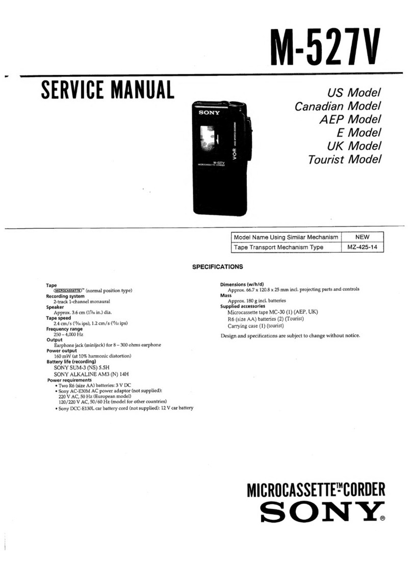
Sony
Sony TC-730 User manual

Sony
Sony PZW-4000 User manual

Sony
Sony STR-DA30ES - Fm Stereo/fm-am Receiver User manual

Sony
Sony PCM-D100 Reference guide

Sony
Sony AXS-R7 User manual

Sony
Sony TC-252 D User manual

Sony
Sony XDCAM EX PMW-EX30 User manual

Sony
Sony BVU-800 User manual