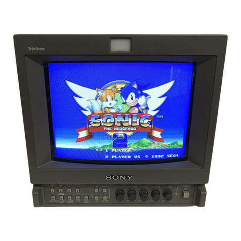
Sony trinitron PVM-1450QM User manual

·SERVICEMANUAL AEP Model
PVM-1450QM:
ChassisNo. SCC-G62C-A
D PVM-1454QM:
ChassisNo. SCC-G628-A
PVM-1450QM PVM-1454QM
SPECIFICATIONS (PVM-1450QM)
Video signal
Color system
Resolution
Aperture correction
Frequency response
PAL, SECAM, NTSC,NTSCw
450TV lines
0dB-+6.0dB
LINE 9.0MHz (-3 dB)
RGB10.0MHz (-3 dB)
Synchronization AFC time constant 1.0msec.
Pidure performance
Normal scan 7% over scan of CRTeffective screen
area
H. linearity Less than 8.0% (typical)
V. linearity Less than 7.0% (typical)
Raster size stability H: 1.0%,V: 1.5%
High voltage regulation
3.5%
CRT P22phosphor
Color temperature 6,SOOK
Inputs and Outputs
Inputs YIC IN: 4-pin mini DIN connector
(See the pin assignment.)
VIDEO IN: BNCconnector
1Vp-p ±6 dB, sync negative
AUDIO IN: phono jack, -5 dBs, more
than 47k ohms
R,G, BIN: BNCconnector
0.7 Vp,p, ±6 dB
Sync on green: 0.3Vp-p, negative,
75 ohms terminated
RGBSYNCIN: BNCconnector
Composite sync 4 Vp-p, ±6 dB,
negative
Loop-through outputs Y/C OUT: 4-pin mini DIN connector
VIDEOOUT: BNC connector,
75ohms terminated
AUDIO OUT: phono jack
Speaker output Output level 0.8W
General
Power consumption 90Wh
Power requirements 100- 240V AC, 50/60 Hz
Operating temperature range
0-35°C
Storage temperature range
-10-+40°C
Humidity 0- 90%
Dimensions Approx. 346 x340 x411.5 mm
(w/h/d)
(13 5/s x 131h x 16 ¼ inches)
not incl. projecting parts and controls
Mass Approx. 16.7kg (36 lb 14 oz)
Accessory supplied AC power cord (1)
AC plug holder (1)
- Continued on page 2 -
TRINITRON@COLORVIDEOMONITOR
SO:NY:

PVM-1450QM/1454QM
Pin assignment
V/C IN connector (4-pin mini DIN)
Pin No. Signal Description
1 Y-input 1 Vp-p, sync negative,
75 ohms
2 CHROMA sub- 300 mVp-p, burst
carrier-input Delay time between Y and C:
within 0+100 nsec., 75 ohms
3 GND for Y-inout GND
4 GND for GND
CHROMA-in out
Design and specifications are subject to change without
notice.
SPECIFICATIONS (PVM-1454QM)
Video signal
Color system
Resolution
Aperture correction
Frequency response
Synchronization
PAL, SECAM, NTSC, NTSCw
600 TV lines
OdB-+6.0dB
LINE 9.0 MHz (-3 dB)
RGB 10.0MHz (-3 dB)
AFC time constant 1.0msec.
Picture performance
7% over scan of CRT effective screen
area
Loop-through outputs
R,G, Bchannels: 0.7 Vp-p, ±6 dB
Sync on green: 0.3 Vp-p, negative,
75 ohms terminated
R-Y,B-Ychannels: 0.7 Vp-p, ~6 dB
Ychannel: 0.7Vp-p, ±6 dB
(Standard color bar signal of 75%
chrominance)
EXTSYNC IN: BNC connector
Composite sync 4 Vp-p, ±6 dB,
negative
YIC OUT: 4-pin mini DIN connector
VIDEO OUT: BNC connector,
Normal scan
Und!!rscan 5% underscan of CRT effective screen 75 ohms terminated
AUDIO OUT: phono jack
H. linearity
V. linearity
Convergence
area
Less than 8.0%(typical)
Less than 7.0%(typical)
Central area:
0.6mm (typical)
Peripheraf area:
0.8mm (typical)
Raster size stability H: 1.0%,V: 1.5%
High voltage regulation
CRT
Color temperature
3.5%
EBU phosphor
6,500K/9,300K (+8MPCD), selectable
USER (3200K-10000K,factory setting
is 6500K)
Inputs and Outputs
Inputs YIC IN: 4-pin mini DIN connector
(See the pin assignment on the next
page.)
VIDEO IN: BNCconnector
1Vp·p ±6 dB, sync negative
AUDIO IN: phono jack, -5 dBs, more
than 47k ohms
R/R-Y, G/Y, B/B-Y IN: BNC
connector
R/R-Y, G/Y, B/B-Y OUT: BNC
connector, 75 ohms terminated
EXTSYNC OUT: BNC connector,
75 ohms terminated
Remote input REMOTE:20-pin connector (See the
pin assignment on the next page.)
Speaker output Output level 0.8 W
General
Power consumption 99 Wh (incl. SDI)
90 Wh (without. SDI)
Power requirements 100- 240 V AC, 50/60 Hz
Operating temperature range
0-35°C
Storage temperature range
-10-+40°C
Humidity O- 90%
Dimensions Approx. 346 x 340 x 411.5 mm
(w/h/d)
(13 '/ • x 13 1
h x 16 1
/
~
inches)
not incl. projecting parts and controls
-2-

Mass Approx. 16.7 kg (36 lb 14 oz)
PVM-2054QM
Accessory supplied AC power cord (1)
AC plug holder (1)
Tally label (1)
Cable with a 20-pin connector (1)
Pin assignment
Y/C IN connector (4-pin mini DIN)
Pin No. Signal Description
1 Y-input l Vp-p, sync negative,
75ohms
2 CHROMA sub- 300 mVp-p, burst
carrier-input Delay time between Yand C:
within 0±100 nsec., 75 ohms
3 GND for Y-input GND
4 GND for GND
CHROMA-input
-3-
PVM-1450QM/1454QM
REMOTE connector (20-pin)
Pin No. Signal Wire color
1 Blue only Brown
2 H/VDELAY Red
3 MAIN/SUB• Orange
4 EXTSYNC Yellow
5 DEGAUSS Green
6 Reh ON/OFF• Blue
7 TALLY Purple
8 LINE B Grey
9 GND White
10 GND Black
11 GND Pink
12 GND Light Blue
13 LINEA Spiral Orange
14 LINE/RGB Spiral Yellow
15 GND Spiral Green
16 Leh ON/OFF* Spiral Blue
17 REMOTE Spiral Purple
18 LINEC Spiral Grey
19 UNDER SCAN Spiral Pink
20 16:9 Spiral Light Blue
(* For digital audio control)
Design and specifications subject to change without notice.

PVM-1450QM/1454QM
TABLE OF CONTENTS
1. GENERAL 5. CIRCUIT ADJUSTMENTS
1-1. General of PVM-1450QM ...................................... 5 5-1. A Board Adjustments······ .................................... 31
I-2. General of PVM-1454QM ···················..··············· l l 5-2. G Board Adjustment ........................................... 41
2. DISASSEMBLY 6. DIAGRAMS
2-I. Top Cover and Rear Cover Removal ···············..······ 19
2-2. Terminal Board Removal····································· 19
2-3. Picture Tube Removal········································· 20
6-1. Block Diagrams (1) ............................................ 43
Block Diagrams (2) ··· ·········· ·· .. ··· ·····.. ······· ···· ······ 48
6-2. Frame Schematic Diagram············· ....................... 53
6-3. Circuit Boards Location········· ..···························· 55
3. SET-UP ADJUSTMENTS 6-4. Printed Wiring Boards and Schematic Diagrams ......... 55
3-1. Preparations (1)····························· .. ··················21 • A Board (1/3)......... ·......... ·· ...... ·... ·.... ···· ..····.... 63
Preparations (2) ····························· ·· .. ···..··········· 23
3-2. Writing Model Data ............................................ 23
3-3. Picture Output ...,... ········ .... ······· ..························ 23
3-4. Landing Adjustment ···.................. ·· ·· ................. · 23
3-5. Convergence Adjustment .. ···· ···...... ··.................... 24
3-6. Deflection Yoke Neck Rotation Adjustment ........... ··· 25
3-7. G2 Adjustment······"·········································· 26
3-8. White Balance Adjustment ·· ·............ ·· ·· ........ ······ ·· 26
3-9. Blue-Only White Balance Adjustment ··· ············· ··· ·· 27
3-IO.Sub Brt Adjustment ·······.. ······························..··· 27
• A Board (2/3)--......... ·.. ·....................... ·· ·· ........ 68
• A Board (3/3).................................................. 73
•QBoard.................. ;...................................... 78
•G Board......................................................... 80
• J Board.......................................................... 82
• X Board......................................................... 82
• H Board····· .. ··..··.... ····· ..··.... ·.... ····· .. ·.... ··.... ···· 82
• C Boa1d······· .................................................. 83
6-5. Semiconductons ..·..······························ ············ ·· 89
3-1I.Focus Adjustment ........................................... ,... 27 7. EXPLODEDVIEWS
7-1. Chassis ............................................................ 91
7-2. Picture Tube····················································· 92
4. SAFETY RELATED ADJUSTMENT ..... ··....··············29 8. ELECTRICAL PARTS LIST····································· 93
(CAUTION)
SHORT CIRCUIT THE ANODE OF THE PICTURE TUBE AND THE
ANODE CAP TO THE METAL CHASSIS, CRT SHIELD, OR CARBON
PAINTED ON THE CRT, AFTER REMOVING THE ANODE.
WARNING!!
AN ISOLATION TRANSFORMER SHOULD BE USED DURING ANY
SERVICE TO AVOID POSSIBLE SHOCK HAZARD, BECAUSE OF
LIVE CHASSIS.
THE CHASSIS OF THIS RECEIVER IS DIRECTLY CONNECTED TO
THE AC POWER LINE.
SAF.ETY-RELATED COMPONENT WARNING!!
COMPONENTS IDENTIFIED BY SHADING AND MARKLt ON THE
SCHEMATIC DIAGRAMS, EXPLODED VIEWS AND IN THE PARTS
LIST ARE CRITICAL TO SAFE OPERATION. REPLACE THESE
COMPONENTS WITH SONY PARTS WHOSE PART NUMBERS
APPEAR AS SHOWN IN THIS MANUAL OR IN SUPPLEMENTS
PUBLISHED BY SONY. CIRCUIT ADJUSTMENTS THAT ARE
CRITICAL TO SAFE OPERATION ARE IDENTIFIED INTHIS MANUAL.
FOLLOW THESE PROCEDURES WHENEVER CRITICAL
COMPONENTS ARE REPLACED OR IMPROPER OPERATION IS
SUSPECTED.
-4-
SECTION 1
GENERAL
The operating instructions mentioned here are partial abstracts from
the Operating Instruction Manual. The page numbers of the
Operating Instruction Manual remein as in the manual.
1-1. GENERAL OF PVM-1450QM
Features
Fine Pitch Trinitron picture tube
Fine Pitch Trinitron tube provides a high resolution picture.
Horizontal resolution is more than 450 TV lines at the center
of the picture.
Four color systems available
The monitor can display PAL, SECAM, NTSC and
NTSCH3* signals. The appropriate color system is selected
automatically.
* A signal of NTSCw is used for playing back NTSC
recorded video cassettes with a video tape recorder/
player especially designed for use with this system.
Analog RGB input connectors
Analog RGBsignals from video equipment can be input
through these connectors.
Y/C input connectors
The video signal, split into the chrominance signal (C) and
the luminance signal (Y),can be input through this
connector, eliminating the interference between the two
signals, which tends to occur in a composite video signal,
assuring video quality.
Beam current feedback circuit
The built-in beam current feedback circuit assures stable
white balance.
Comb filter
When NTSC video signals are received, a comb filter
activates to increase the resolution, resulting in fine picture
detail without color spill or color noise.
Automatic termination
(connector with 1\/v-mark only)
The input connector is terminated at 75 ohms inside when
no cable is connected to the loop-through output
connectors. When a cable is connected to an output
connector, the 75-ohms termination is automatically
released.
Blue only mode
In the blue only mode, an apparent monochrome display is
obtained with all three cathodes driven with a blue signal.
This facilitates color saturation and phase adjustments and
observation of VCR noise.
Auto/manual degaussing
Degaussing of the screen can be performed automatically
when the power is turned on, or manually by pressing the
DEGAUSS button.
On-screen menus
You can set CHROMA SET UP and other settings by using
the on-screen menus.
Five menu languages
You can select the menu language from among the five
languages on the menu.
EIA standard 19-inch rack mounting
Byusing an MB-502Bmounting bracket (not supplied), the
monitor can be mounted in an EIA standard 19-inch rack.
For details on mounting, see the instruction manual of the
mounting bracket kit.
-5-
1

Location and function of parts and controls
Front panel
[I] POWER switch and indicator
Depress to turn the monitor on. The indicator will light
up in green.
(g]VOLUME control
Turn this control clockwise or counterclockwise to
obtain the desired volume.
m)CONTRAST control
Turn clockwise to make the contrast higher and
counterclockwise to make it lower.
@]PHASE control
This control is effective only for the NTSC and NTSC4.43
color systems. Turn clockwise to make the skin tones
greenish and counterclockwise to make them purplish.
(IDCHROMA control
Turn clockwise to make the color intensity higher and
counterclockwise to make it lower.
[IDBRIGHT (brightness) control
Turn clockwise for more brightness and
counterclockwise for less.
[I] APERTUREcontrol
Turn clockwise for more sharpness and
counterclockwise for less.
l~Mtl
The APERTURE, CHROMA, PHASE control settings have
no effect on the pictures of RGB signals.
2
BRIGHT CHROMA PHASE CONTRASTVOLUME
1
[IDMENU (EXIT) button
Press to make the menu appear. Press to return to the
previous screen in the menu.
[IDENTER (SELECT) button
Press to decide a selected item in the menu.
[IQlt (+)/ .J(-) buttons
Press to move the cursor (Iii-)or adjust selected value in
the menu.
[DJBLUE ONLY selector
RESETbutton
Press (light on) to turn off the red and green signals. A
blue signal is displayed as an apparent monochrome
picture on the screen. This facilitates "chroma" and
"phase*" control adjustments and observation of VCR
noise.
* "Phase" control adjustment is effective only for the
NTSC signals.
Press to reset the setting in the menu.
[gj DEGAUSS button
Press this button momentarily. The screen will be
demagnetized. Wait for 10 minutes or more before
activating this button again.
~
,nput select buttons
Press (light on) to select the program to be monitored.
A: for a signal fed through the LINE A connectors.
-6-
B: for a signal fed through the LINE Bconnectors.
C: for a signal fed through the LINE C connectors.
RGB: for a signal fed through the RGB connectors.

Rear panel
1 2
LINE A LINE B
'v p.
CIN VIDEO VIDEO
~
D.fl IN OUT IN OUT
e:
~
~
~~
AUDIO AUDIO
IN OUT IN OUT
@) ©) ©) @)
ll@LI, IN IN
I~
~
R G
[I] AC IN socket
Connect the supplied AC power cord to this socket and
to a wall outlet.
[g)LINE A, LINE B connectors
Two groups (A and B)of line input connectors for the
composite video and audio signals and their loop-
through output connectors.
To monitor the input signal fed through these
connectors, press the A or Bbutton (light on) on the
front panel.
VIDEO IN (BNC)
Connect to the video output of video equipment, such as
a VCR or a color video camera. For a loop-through
connection, connect to the video output of another
monitor.
VIDEO OUT (BNC)
Loop-through output of the VIDEO IN connector.
Connect to the video input for a VCR or another
monitor.
When the cable is connected to this connector, the
75-ohms termination of the input is automatically
released, and the signal input to the VIDEO IN
connector is output from this connector.
AUDIO IN (phono jack)
Connect to the audio output of a VCR or to a
microphone via a suitable microphone amplifier. For a
loop-through connection, connect to the audio output of
another monitor.
AUDIO OUT (phono jack)
Loop-through output of the AUDIO IN jack. Connect to
the audio input of a VCR or another monitor.
RGB
3
LINE C
YIC
IN OUT
@<@>
.- .- r ,..
,... ,...
AUDIO
IN OUT
©) @
IN IN IN
~ ©> ~I
B AUDIO SYNC
4 (The 'V\r mark indicates autom;it1c termination.)
~
LINE C connectors
VIC IN (4pin mini DIN)
Connect to the YJC separate output of a video camera,
VCR or other video equipment.
VIC OUT (4pin mini DIN)
Loop-through output of the YJC IN connector. Connect
to the YJCseparate input of ii VCR or another monitor.
When the cable is connected to this connector the
75-ohms termination of the input is ilUtomatirnlly
released, and the signal input to the YJC IN connector is
output from this connector.
AUDIO IN (phono jack)
Connect to the audio output of ct VCR or a microphone
(through ii-suitable microphone mnplifier).
AUDIO OUT (phono jack)
Loop-through output of the AUDIO IN connector.
Connect to the audio input of a VCR or another monitor.
@]RGB IN connectors
Connect to the analog RGBoutputs of a video camera.
To monitor the input signal fed through these
connectors, press RGB button (light on) nn the front
panel.
R IN, G IN, B IN (BNC)
When you set RGBSYNC to SYNC ONG in the menu,
the monitor operates on the sync signal from the G
channel.
AUDIO IN (phono jack)
Connect to the audio output of video equipment when
the anil!og RGB signal is input.
SYNC IN (BNC)
To use the sync signal fed through this connector, set
RGB SYNC to EXTSYNC in the menu.
3
-7-

Using on-screen menus
The flow chart shows the different levels of on-screen
menus that you can use to make various adjustments and
settings. The boxed number is for instructions on the next
page.
[D Main menu
MENU
.. CHROMA SET UP
USER CONFIG
lflf 1
SELECT [r."iii)
4
[gJCHROMA SETUP menu
CHROMA SET UP
•OFF
ON
-AUTO ADJUST
lflflSELECT ii"...,.;i
[IDUSERCOMFIG 1 menu
USER CONF IG 1
"'COLOR SYSTEM O I SPLAY
V HOLD
NEXT PAGE
flWSELECT [-,iol
@]USERCONFIG 2 menu
USER CONF IG 2
• RGB SYNC
NTSC SETUP LEVEL
LANGUAGE
PREVIOUS PAGE
IJJfJSEl:ECT
~
_.,. [fil AUTO ADJUST screen
,: [IDCOLOR SYSTEM DISPLAY menu
[I] V HOLD screen
!IDRGB SYNC menu
[IDNTSC SETUP LEVEL menu
[IQ)LANGUAGE menu
-8-

Operating through menus
There are five buttons for menu operations on the front of
the monitor. To display the main menu, first press MENU.
The buttons you can use appear at the bottom of the menu
screen.
Functions of the buttons
Button To select menu To adjust menu item
Item selected
MENU return to the return to the previous
lli:HII previous menu menu
ENTER decide a selected select an item
E:~!!!:11
item
t move the cursor increase selected value
-(..,.)upwards
• move the cursor decrease selected value
(..,.)downwards
ldi1il reset current adjustment
value to the factory
setting
(The above items in white type correspond to the marks in
the menu.)
front of monitor
RESET
button
[IJ Main menu
buttons for
menu
operations
Select an item and press ENTER to go to the following
menu.
[g)CHROMA SET UP menu
Set to ON to adjust the internal decoder for CHROMA
and PHASE after AUTO ADJUST([§]). IOFFI
@]USER CONFIG 1 menu
Select an item to adjust. To go to the USER CONFIG 2
menu select NEXT PAGE.
-9-
@]USER CONFIG 2 menu
Select an item to adjust. To go to the USERCONFIG 1
menu select PREVIOUS PAGE.
[§] AUTO ADJUST screen
Select the color bar signal (full, SMPTE, EIA) and press
ENTER to start auto adjusting for CHROMA SET UP
(NTSC signal only).
[IDCOLOR SYSTEM DISPLAY menu
Select the color system display mode. In AUTO, the kind
of color system being used appears on the screen each
time you change the signal input. [AUTO[
II] V HOLD screen
Adjust the vertical hold if the picture rolls vertically.
When you cannot read the display, select the input that
is not connected .
[illRGB SYNC menu
Select SYNC ON G to operate the monitor on the sync
signal from the displayed green signal.
Select EXTSYNC to operate the monitor on an external
sync signal fed through the RGB SYNC connector.
[SYNC ON Gl
[IDNTSC SETUP LEVEL menu
Select the NTSC setup level from two modes. The 7.5
setup level is mainly used in north America. The Osetup
level is mainly used in Japan. IOI
[Q]LANGUAGE menu
You can select the menu language from among the five
languages (English, German, French, Italian, Spanish) on
the menu. IENGLISH I
([ ]indicates the factory setting position.)
5

Power sources
House current
Connect the AC power cord (supplied) to the AC IN socket
and to a wall outlet.
to AC IN to a wall outlet
~i:::========= ...
To connect an AC power cord securely with an AC plug holder
1 AC IN socket
AC plug holder
!'lug the power cord into the AC IN socket. Then, attach the
AC plug holder (supplied) on top of the AC power cord.
To remove the AC power cord
Pull out AC plug hokk•r by squeezing the left and right sides.
6
2
Slide the AC plug holder over the cord until it connects
with the attached holder.
-10-

1-2. GENERAL OF PVM-14540M
Features
HR (High Resolution) Trinitron picture tube
HR Trinitron tube provides a high resolution picture ..
Horizontal resolution is more than 600TV lines at the center
of the picture.
Four color systems available
The monitor can display PAL, SECAM, NTSC and NTSCu)•
signals. The appropriate color system is selected
automatically.
• A signal of NTSCw is used for playing back NTSC
recorded video cassettes with a video tape recorder/
player especially designed for use with this system.
Blue only mode
In the blue only mode, an apparent monochrome display is
obtained with all three cathodes driven with a blue signal.
This facilitates color saturation and phase adjustments and
observation of VCR noise.
Analog RGB/component input connectors
Analog RGB or component (Y,R-Yand B-Y)signals from
video equipment can be input through these connectors.
Y/C input connectors
The video signal, split into the chrominance signal (C) and
the luminance signal (Y),can be input through this
connector, eliminating the interference between the two
signals, which tends to occur in a composite video signal,
assuring video quality.
Beam current feedback circuit
The built-in beam current feedback circuit assures stable
white balance.
Comb filter
When NTSC video signals are received, a comb filter
activates to increase the resolution, resulting in fine picture
detail without color spill or color noise.
Automatic termination
(connector with V'v mark only)
The input connector is terminated at 75 ohms inside when no
cable is co1inected to the loop-through output connectors.
When a cable is connected to an output co1mector,the
75-ohms termination is automatically released.
Underscan mode
The sign.ii normally sc.inned outside of the screen can be
monitored in the undersc.in mode.
,~mrw
When the monitor is in the underscan mode, the dark RGB
scanning lines may appear on th~ top edge of the screen.
These are mused by an internal test signal, rather th.in the
input sign.ii.
Horizontal/vertical delay mode
The horizontal and vertical sync signals can be checked
simultaneously in the H/V delav mode.
External sync input
When the EXTSYNC selector is in the on position, the
monitor can be operated on the sync signal supplied from
an external sync generator.
Auto/manual degaussing
Degaussing of the screen can be performed automatically
when the power is turned on, or manually by pressing the
DEGAUSSbutton.
On-screen menus
Youcan set color temperature, CHROMA SET UP, .ind
other settings by using the on-screen menus.
Five menu languages
Youcan select the menu language from among the five
languages on the menu.
EIA standard 19-inch rack mounting
Byusing an MB-502B(for PVM-1454QM) or SLR-103 (for
PVM-2054QM)mounting bracket (not supplied), the
monitor can be mounted in an EIAstandard 19-inch rack.
Fordetails on mounting, see the instruction manual of the
mounting bracket kit.
SDI (Serial Digital Interface) kit
Byusing SDI kit, the monitor can display SMPTE 259M 4:2:2
serial digital signal from a digital VTR. (ex. Sony 4:2:2 VTR)
SDIkit: 4:2:2digital video board
Digital audio board
1
-11 -

Location and function of parts and controls
Front panel
[Il Tally lamp
Lights up when the video camera connected to this
monitor is selected, indicating that the picture is being
recorded.
~
POWER switch and indicator
Depress to tum the monitor on. The indicator will light
up in green.
~
REMOTE indicator
Lights up when you set USER PRESETto ON in the
menu, or when you connect a supplied cable to
REMOTE connector (No. 17 pin is ground). The controls
on the front panel do not work when this indicator lights
up.
@]VOLUME control
Turn this control clockwise or counterclockwise to
obtain the desired volume.
[fil CONTRAST control
Turn clockwise to make the contrast higher and
counterclockwise to make it lower.
[IDPHASE control
2
This control is effective only for the NTSC and NTSCw
color systems. Turn clockwise to make the skin tones
greenish and counterclockwise to make them purplish.
1
[z) CHROMA control
Turn clockwise to make the color intensity higher and
counterclockwise to make it lower.
[IDBRIGHT {brightness) control
Turn clockwise for more brightness and
counterclockwise for less.
(IDAPERTURE control
Turn clockwise for more sharpness and
counterclockwise for less.
,~ma
The APERTURE, CHROMA, PHASE control settings have
no effect on the pictures of RGB signals.
[gj MENU {EXIT) button
Press to make the menu appear. Press to return to the
previous screen in the menu.
[11ENTER {SELECT) button
Press to decide a selected item in the menu.
[gj t (+)/ .f.H buttons
Press to move the cursor(..,.) or adjust selected value in
the menu.
-12 -

~
16:9 selector
Press (light on) for the signal of 16:9 picture.
~
HN DELAY selector
Press (light on) to observe the horizontal and vertical
sync signals at the same time.
The horizontal sync signal is displayed in the left quarter
of the screen; the ,·ertical sync signal is displayed near
the center of the screen.
[§I UNDER SCAN selector
Press (light on) for underscanning. The display size is
reduced by approximately 5% so that four comers of the
raster are visible.
ff§]BLUE ONLY selector
RESET button
Press (light on) to turn off the red and green signals. A
blue signal is displayed as an apparent monochrome
picture on the screen. This facilitates "chroma" and
"phase*" control adjustments and observation of VCR
noise.
* "Phase" control adjustment is effective only for the
NTSC signals.
Press to reset the setting in the menu.
[UjDEGAUSS button
Press this button momentarily. The screen will be
demagnetized. Wait for 10 minutes or more before
activating this button again.
[ill EXT SYNC (external sync) selector
Keep this button in the off position (light off) to operate
the monitor on the sync signal from the displayed video
signal.
Keep this button in the on position (light on) to operate
the monitor on an extem11lsync signal fed through the
EXTSYNC connector on the rear panel.
~
LINE/RGB input selector
Select the program to be monitored. Keep this button in
the off position (light off) to feed a signal through the
LINE A, LINE Bor LINE C connectors. Keep this button
in the on position (light on) to feed a signal through the
RGBconnectors.
~
C/SDI selector
When the LINE/RGB input selector is set to LINE (light
off), press this button (light on) to feed a signal through
the LINE C connectors.
When the LINE/RGB input selector is set to RGB(light
on), press this button (light on) to feed the SD! signal
(optional board is needed).
~
B/COMPONENT selector
When the LINE/RGB input selector is set to LINE (light
off), press this button (light im) to feed a signal through
the LINE B connectors.
When the LINE/RGB input selector is set to RGB(light
on), press this button (light on) to feed the component
signal.
-13-
~
A/RGB selector
When the LINE/RGB input selector is set to LINE (light
off), press this button (light on) to feed a signal through
the LINE A connectors.
When the LINE/RGB input selector is set to RGB(light
on), press this button (light on) to feed the RGBsignal.
3

Location and function of parts and controls
Rearpanel
LINE A LINE B
VIDEO VIDEO
IN OUT IN OUT
AUDIO AUDIO
IN OUT IN OUT
©) ©) ©) ©) IN
@
3
LI C
AUDIOOUT
©)
IN OUT IN OUT IN OUT IN
R/A-Y G/Y BIB-Y
RGBICOM ONENT
5
(The Vv- mark indicates automatic termination.)
II] AC IN socket AUDIO IN (phono jack)
Connect the supplied AC power cord to this socket and
to a wall outlet.
[g] LINE A, LINE B connectors
4
Two groups (A and B)of line input connectors for the
composite video and audio signals and their loop-
through output connectors.
To monitor the input signal fed through these
connectors, keep the LINEIRGB selector in the LINE
position (light off) and press the AIRGB or
BICOMPONENT selector (light on) on the front panel.
VIDEO IN (BNC)
Connect to the video output of a video equipment, such
as a VCR or a color video camera. For a loop-through
connection, connect to the video output of another
monitor.
VIDEO OUT (BNC)
Loop-through output of the VIDEO IN connector.
Connect to the video input for a VCR or another
monitor.
When the cable is connected to this connector, the
75-ohms termination of the input is automatically
released, and the signal input to the VIDEO IN
connector is output from this connector.
Connect to the audio output of a VCR or to a
microphone via a suitable microphone amplifier. For a
loop-through connection, connect to the audio output of
another monitor.
AUDIO OUT (phono jack)
Loop-through output of the AUDIO IN jack. Connect to
the audio input of a VCR or another monitor.
@ILINE C connectors
Y/C IN (4pin mini DIN)
Connect to the YIC separate output of a video camera,
VCR or other video equipment.
Y/C OUT (4pin mini DIN)
Loop-through output of the YIC IN connector. Connect
to the YIC separate input of a VCR or another monitor.
When the cable is connected to this connector, the
75-ohms termination of the input is automatically
released, and the signal input to the YIC IN connector is
output from this connector.
AUDIO IN (phono jack)
Connect to the audio output of a VCR or a microphone
(through a suitable microphone amplifier).
-14-
AUDIO OUT (phono jack)
Loop-through output of the AUDIO IN connector.
Connect to the audio input of a VCR or another monitor.

@]REMOTE connector (20pin)
Connect to the tally output of a control console, special-
effect generator, etc. The tally lamp on the front panel
will be turned on and off by the connected equipment.
This connector can be used for connecting a remote
controller. For the pin assignment of this connector, see
"Specifications" on page 10.
[§)RGB/COMPONENT connectors
RGBsignal or component signal input connectors and
their loop-through output connectors.
To monitor the input signal fed through these
connectors, keep the LINE/RGB selector in the RGB
position (light on), and press the A/RGB or
B/COMPONENT selector (light on) on the front panel.
R/R-Y IN, G/Y IN, B/B-Y IN {BNC)
When the EXT SYNC selector on the front panel is in the
off position (light off), the monitor operates on the sync
signal from the G/Y channel.
To monitor the RGB signal
Connect to the analog RGBsignal outputs of a video
camera.
To monitor the component signal
Connect to the R-Y/Y /B-Y component signal outputs of
a Sony Betacam video camera.
R/R-Y OUT, GfY OUT, B/B-Y OUT {BNC)
Loop-through outputs of the R/R-Y IN, G/Y IN, B/B-Y
IN connectors '
For RGB signal
Connect to the analog RGBsignal inputs of a video
printer or another monitor.
For component signal
Connect to the R-Y/Y /B-Y component signal inputs of a
Betacam video recorder.
When the cables are connected to these connectors, the
75-ohms termination of the inputs is automatically
released, nnd the signal inputs to the R/R-Y IN, G/Y IN,
B/B-Y IN connectors are output from these connectors.
AUDIO IN (phone jack)
Connect to the audio output of video equipment when
the analog RGB or component signal is input.
AUDIO OUT (phone jack)
Loop-through outputs of the AUDIO IN connector.
[§] EXT SYNC (external sync) connectors
To use the sync signnl fed through this connector, press
the EXTSYNC selector (light on).
IN (BNC)
When this monitor operates-on an external sync signal,
connect the reference signal from a sync generator to this
connector.
OUT (BNC)
Loop-through output of the EXTSYNC IN connector.
Connect to the external sync input of video equipment to
be synchronized with this monitor.
When the cable is connected to this connector, the 75-
ohms termination of the input is released, and the signal
input to the IN connector is output from this connector.
-15-5

Using on-screen menus
The flow chart shows the different levels of on-screen
menus that you can use to make various adjustments and
settings. The boxed number is for instructions on the next
page.
(I] Main menu
MENU
(2]CHROMA SET UP menu
CHROMA SET UP
•OFF
°"
to CHROMA SET UP
COLOR TEMP/BAL
USER CONFIG -AUTO ADJUST ~- [IDAUTO ADJUST screen
i(J)SELECT
~
6
msELECT !Ira
~
COLORTEMP/BAL menu
COLOR TEMP I BAL
,.esoot<.
9300K
USER(.,,.ITE BAL)
-ADJUST GAIN
-AO JUST BI AS
-COL OR TEMP RANGE
111])SELECT IE[l
@)USERCONFIG 1 menu
USER CONF I G 1
• COLOR SYSTEM O I SP'LAY
358TFtAP FILTER
SUB CONTROi.
USER PRESET
V HOLD
NEXT PAGE
lllllSELECT IE;j
(IDUSERCONFIG2 menu
USER CONF I G 2
,. COMPONENT LEVEL
NTSC SETUP LEVEL
ACC
LANGUAGE
PREVIOUS PAGE
IDI'SELECT
~
t
E
-16-
[z) ADJUST GAIN screen
[IDADJUST BIASscreen
(IDCOLORTEMP RANGE menu
[j] COLOR SYSTEM DISPLAYmenu
fl] 358 TRAP FILTERmenu
[illSUB CONTROLscreen
~
USER PRESETmenu --+ [j]] PRESETADJUST screen
[i]l V HOLD screen
[i] COMPONENT LEVELmenu
[ii NTSC SETUP LEVELmenu
[i] ACC menu
Ii]] LANGUAGEmenu

Operating through menus
There are five buttons for menu operations on the front of
the monitor. To display the main menu, first press MENU.
The buttons you can use appear at the bottom of the menu
screen.
Functions of the buttons
Button To select menu To adjust menu item
item selected
MENU return to the return to the previous
.:i:li• previous menu menu
ENTER decide a selected select an item
lja!~:51 item
move the cursor increase selected value
--(.,..)upwards
move the cursor decrease selected value
(.,..)downwards
ligilll reset current adjustment
value to the factory
setting
(The above items in white type correspond to the marks in
the menu.)
front of monitor
Bl Ci LINE/ EXT
COMPONENTSDI AGB SYNC
D D G [CJ
..
wD Q D
BL E UNDER HIV 16:9
0 LY SCAN DELAY
RESET
button
[Il Main menu
buttons for
menu
operations
Select an item and press ENTER to go to the folio.wing
menu.
~
CHROMA SET UP menu
Set to ON to adjust the internal decoder for CHROMA
and PHASE (NTSC signal only) after AUTO ADJUST
(ffi]). (OFF)
@)COLOR TEMP/BAL menu
Select the color temperature from among 6500K, 9300K
and USER. USER is set to 6500K in the factory setting.
You can adjust or change the color temperature in USER
mode (a measuring instrument is needed). (6500K)
@]USER CONFIG 1 menu
Select an item to adjust. To go to the USER CONFIG 2
menu, select NEXT I'AGE.
ffi) USER CONFIG 2 menu
Select an item to adjust. To go to the USER CONr-IG 1
menu select PREVIOUS PAGE.
[IDAUTO ADJUST screen
Select the color bar signal (full, SMPTE, EIA) and press
ENTER to start auto adjusting for CHROMA SET UP
(NTSC signal only).
(l] ADJUST GAIN screen
Adjust GAIN in USER mode.
(IDADJUST BIAS screen
Adjust BIAS in USER mode.
(IDCOLOR TEMP RANGE menu
Select the color temperature range in USER mode.
[S0OOK-lOO00K)
[illCOLOR SYSTEM DISPLAY menu
Select the color system display mode. In AUTO, the kind
of color system being used appears on the screen each
time you change the signal input. (AUTO)
[TI]358 TRAP Fil TER menu
Color spill or color noise may be eliminated if you select
ON (NTSC signal only). !OFF!
[gj SUB CONTROL screen
You can finely adjust the controls on the front panel.
CONTRAST, BRIGHT, CHROMA and PHASE control
has a click at the center of its adjustment range. You can
adjust the setting of the click position with this feature.
~
USER PRESET menu
You can preset each control to a desired level and set it.
If you set USER PRESETto ON, the REMOTE indicator
lights up and the controls on the front panel do not
work. The monitor operates with the internal memory
settings. For adjustment, select PRESET ADJUST. [OFF!
~
PRESET ADJUST screen
Adjust CONTRAST, BRIGHT,CHROMA, PHASE,
VOLUME, APERTURE in USER PRESET.
[ill V HOLD screen
Adjust the vertical hold if the picture rolls vertically.
When you cannot read the display, select the input that
is not connected.
[j]] COMPONENT LEVEL menu
Select the component level from among three modes.
N10/SMPTE for 100/0/100/0 sign.ii
BETA 7.5 for 100/7.5/75/7.5 signal
BETAO for 100/0/75/0 signal [N10/SMPTEI
[TI]NTSC SETUP LEVEL menu
Select the NTSC setup level from two modes. The 7.5
setup level is mainly used in north America. The 0 setup
level is mainly used in Japan. [OJ
5]IACC menu
Set ACC (Auto Color Control) circuit on or off. When the
fine adjustment is needed, set ACC to OFF. Normally set
it to ON. [ONI
~
LANGUAGE menu
You can select the menu language from among the five
languages (English, German, French, Italian, Spanish) on
the menu. [ENGLISH!
(I Iindicates the foctory setting position.)
7
-17-

Power sources
House current
Connect the AC power cord (supplied) to the AC IN socket
and to a wall outlet.
to AC IN to a wall outlet
efilD::=========--+-
To connect an AC power cord securely with an AC plug holder
1 AC IN socket
AC plug holder
Plug the power cord into the AC IN socket. Then, attach the
AC plug holder (supplied) on top of the AC power cord.
To remove the AC power cord
Pull out AC plug holder by squeezing the left and right sides.
8
2
Slide the AC plug holder over the cord until it connects
with the attached holder.
-18-

SECTION 2
DISASSEMBLY
2-1.TOP COVERAND REARCOVERREMOVAL
PVM-1450QM/1454QM
~G) Three screws
.,-- , (CASE CLAW SCREW(OS))
@Rear cover
2-2.TERMINALBOARDREMOVAL
A board
- 19-
I
I © Top cover

PVM-1450QM/1454QM
2-3. PICTURE TUBE REMOVAL
@ Cboard
@ Delledfo, yoke
~
@ Four screws
(TAPPING SCREW(5))
(z)Towscrew
(+BVTT 4 X B(S))
•REMOVALOFANOD~CAP
@ Chassis assy
1
@rwoscrews
(+BVTT 4 x B(S))
©Gbracket
@ Picture tube shield
NOTE : Short circuit the anode of the picture tube and the anode cap to the metal chassis, CRT shield or carbon
paint on the CRT, after removing the anode.
• REMOVINGPROCEDURES
~@
~
CDTurn up one side of the rubber cap in the ® Using a thumb pull up the rubber cap
direction indicated by the arrow@. firmly in the direction indicated by the
arrow@.
• HOW TO HANDLE AN ANODE-CAP
CD Don't hurt the surface of anode-caps with
sharp shaped material!
® Don't press the rubber hardly not to hurt
inside of anode-caps!
A material fitting :called as shatter-hook
terminal is built in the rubber.
@ Don't turn the foot of rubber over hardly!
The shatter-hook terminal will stick out or
hurt the rubber.
- 20 -
@ When one side of the rubber cap is
separated from the anode button, the
anode-cap can be removed by turning up
the rubber cap and pulling up it in the
direction of the arrow ©.
This manual suits for next models
1
Table of contents
Other Sony Monitor manuals

Sony
Sony Trinitron CPD-E200 User manual

Sony
Sony LMD-151MD User manual

Sony
Sony TRINITRON BVM-14M4DE User manual

Sony
Sony BVM-1911 User manual

Sony
Sony PVM-5041Q User manual

Sony
Sony BRAVIA FW-85BZ35F User manual

Sony
Sony SDM-S51 User manual

Sony
Sony BVM-L230 Trimaster User manual

Sony
Sony LMD-940W User manual

Sony
Sony TRINITRON CDP-4402 User manual

Sony
Sony LMD-3250MD User manual

Sony
Sony SDM-HX93 User manual

Sony
Sony GDM-17SE1/P User manual

Sony
Sony FD Trinitron CPD-L181A User manual

Sony
Sony Wahoo CLM-V55 User manual

Sony
Sony Trinitron CPD-200SX User manual

Sony
Sony SDM-HS74 User manual

Sony
Sony BVM-E250 User manual

Sony
Sony CPD-110GS User manual

Sony
Sony SDM-V76D User manual