Sony UP-D70XR User manual

DIGITAL COLOR PRINTER
UP-D70XR
SERVICE MANUAL
Volume 1 1st Edition

UP-D70XR
!WARNING
This manual is intended for qualified service personnel only.
To reduce the risk of electric shock, fire or injury, do not perform any servicing other than that
contained in the operating instructions unless you are qualified to do so.Refer all servicing to
qualified service personnel.
!WARNUNG
Die Anleitung ist nur für qualifiziertes Fachpersonal bestimmt.
Alle Wartungsarbeiten dürfen nur von qualifiziertem Fachpersonal ausgeführt werden.Um die
Gefahr eines elektrischen Schlages, Feuergefahr und Verletzungen zu vermeiden, sind bei
Wartungsarbeiten strikt die Angaben in der Anleitung zu befolgen. Andere als die angegeben
Wartungsarbeiten dürfen nur von Personen ausgeführt werden, die eine spezielle Befähigung
dazu besitzen.
!AVERTISSEMENT
Ce manual est destiné uniquement aux personnes compétentes en charge de l’entretien.Afin
de réduire les risques de décharge électrique, d’incendie ou de blessure n’effectuer que les
réparations indiquées dans le mode d’emploi à moins d’être qualifié pour en effectuer d’autres.
Pour toute réparation faire appel à une personne compétente uniquement.

1
UP-D70XR
Table of Contents
Manual Structure
Purpose of this manual .............................................................................................. 3
Related manuals......................................................................................................... 3
1. Operating Instructions
2. Service Information
2-1. Process Order When Replacing Each Part ..................................................2-1
2-2. Location of Main Parts................................................................................2-3
2-3. Disassembly ................................................................................................2-4
2-4. Assembling Method of Stepping Motor....................................................2-10
3. Mechanical Operation
3-1. Motor...........................................................................................................3-1
3-2. Timing of Mechanical Operation ................................................................3-1
3-3. Mechanical Section Outline ........................................................................3-3
3-4. Position and Function for Sensor ................................................................3-4
3-5. Printing Operation Description ...................................................................3-5
3-6. Timing for Bar Code Detection.................................................................3-11
4. Circuit Operation Description
4-1. SY-270 Board, MEC-11 Board Circuit Operation Description ..................4-1
5. Service Mode
5-1. Service Mode ..............................................................................................5-1
5-2. Adjust Mode................................................................................................5-9
5-3. FMY Printing ............................................................................................5-11
5-4. Reset of Each Kind Setting Value.............................................................5-12
5-5. Note on the Unit Transportation ...............................................................5-13

2UP-D70XR
6. Troubleshooting
6-1. Mechanical Section .....................................................................................6-1
6-2. Electrical Section ........................................................................................6-3

3
UP-D70XR
Manual Structure
Purpose of this manual This manual is the Service Manual Vol.1 of the Digital Color Printer UP-D70XR.
This manual contains the operating instructions, service information, mechanical
operation, circuit operation description, service mode and troubleshooting.
Related manuals In addition to this Service Manual Vol.1, the following manual is provided.
..
..
.Service Manual Vol.2
Part No.: 9-955-293-21 (for J, UC, CE)
Contains the semiconductor pin assignment, spare parts, block diagrams,
schematic diagrams and board layouts.
..
..
.Instruction Manual
Part No.: 3-868-050-11
This manual describes the information required for the actual management and
operation of this unit.
..
..
.Service Manual
UPK-8802RT (RASTER INTERFACE KIT)
Part No.: 9-974-788-01 (for J/CE)
9-974-777-01 (for UC)
Contain the semiconductor pin assignment, spare parts, block diagrams, schematic
diagrams and board layout of FMY-15 and IF-601 boards.


1-1
UP-D70XR
Section 1
Operating Instructions Reprinted from the
operating instructions
Digital Color
Printer
Operating Instructions
Page 2 US
1999 Sony Corporation
UP-D70XR
3-868-050-11 (1)
1-2 UP-D70XR
2
English
Owner’s Record
The model and serial numbers are located at the rear.
Record these number in the space provided below.
Refer to these numbers whenever you call upon your
Sony dealer regarding this product.
Model No.
Serial No.
WARNING
To prevent fire or shock hazard, do not expose the unit
to rain or moisture.
To avoid electrical shock, do not open the cabinet. Refer
servicing to qualified personnel only.
THIS APPARATUS MUST BE EARTHED.
For the customers in the U.S.A.
This equipment has been tested and found to comply
with the limits for a Class A digital device, pursuant to
Part 15 of the FCC Rules. These limits are designed to
provide reasonable protection against harmful
interference when the equipment is operated in a
commercial environment. This equipment generates,
uses, and can radiate radio frequency energy and, if not
installed and used in accordance with the instruction
manual, may cause harmful interference to radio
communications. Operation of this equipment in a
residential area is likely to cause harmful interference in
which case the user will be required to correct the
interference at his own expense.
You are cautioned that any changes or modifications not
expressly approved in this manual could void your
authority to operate this equipment.
This device requires shielded interface cable to comply
with FCC emission limits.
As an
E
NERGY
S
TAR
Partner, Sony Corporation
has determined that this
product meets the
ENERGY STAR guidelines
for energy efficiency.
Outline of the International ENERGY
STAR Office Equipment Program
The International ENERGY STAR Office Equipment
Program is an international program that promotes
energy saving through the use of computers and
other office equipment. The program backs the
development and dissemination of products with
functions that effectively reduce energy consumption.
It is an open system in which business proprietors
can participate voluntarily. The targeted products are
office equipment such as computers, displays,
printers, facsimiles, and copiers. Their standards and
logos are uniform among participating nations.
3
Table of Contents
US
English
Table of Contents
Introduction
About this Manual .............................................................4
System Overview ..............................................................5
System Configuration....................................................... 5
Location and Function of Parts and Controls ................6
Front ................................................................................. 6
Rear .................................................................................. 7
Preparation
Supplied Accessories.......................................................8
Assembly.......................................................................... 9
Connections ....................................................................10
Connecting the Computer .............................................. 10
Installing the Printer Driver Program............................. 11
Setting the DIP Switch ................................................... 11
Connecting the AC Power Cord..................................... 12
Setting the SCSI Device Type........................................ 13
Operation
Before Printing ................................................................14
Loading an Ink Ribbon Cassette .................................... 14
Loading the Print Paper.................................................. 17
Printing.............................................................................20
Setting the Print Quantity...............................................23
Adjusting the Printouts ..................................................24
Adjusting the Gray Balance ...........................................26
Selecting the Gamma Curve ..........................................28
Setting the Margin Print Option .....................................29
Others
Precautions......................................................................30
Safety.............................................................................. 30
Installation...................................................................... 30
On Transportation .......................................................... 31
Cleaning ......................................................................... 31
Ink Ribbon and Print Paper ............................................33
Specifications..................................................................34
Troubleshooting..............................................................35
Error Messages............................................................... 35
If the Paper Jams ............................................................ 37
Index.................................................................................39
1-3
UP-D70XR
4
Introduction
Note
Introduction
About this Manual
Organization of this manual
This manual is divided into four chapters. This section explains the organization of
this manual.
Introduction
Describes the features and system configuration of the digital color printer. Also
provided is information on the location and function of parts.
Preparation
Explains the steps involved in setting up and connecting the printer prior to getting
started —checking the supplied accessories and assembly. Once all assembly and
all connections have been made, there should be no need to perform these
operations again during normal printing operations.
Operation
Describes loading of the ink ribbon cassette and print paper and actual printing
operation. Also provided is information on setting the print quantity and adjusting
the printouts and gray balance.
Others
Provides technical information on the printer, how to handle error messages
displayed in the printer window display, and how to deal with paper jams. Also the
index will assist you to locate the necessary section quickly. Refer to this chapter
when questions arise or problems occur.
Conventions used
Cross reference
Throughout this manual you will find the references to other sections of the manual
that contain related information.
Important note
Be sure to read the sections of the manual marked . They explain points that
you should be aware of to operate the printer correctly and prevent malfunctions.
Trademarks
Macintosh is the trademark of Apple Computer, Inc., USA.
Windows and Windows95 are the trademarks of Microsoft Corporation, USA.
5
Introduction
System Overview
The Sony UP-D70XR digital color printer is designed to reproduce computer
images on A4-size and Letter-size print paper.
You can print out image data of Windows or Macintosh graphics application
software in high resolution (300dpi) and 256 shades of gray or in full color
(16,700,000 colors).
Combined with the UPA-D3 digital image processor (not supplied), you can use
the UP-D70XR as a printer conforming to the DICOM standard.
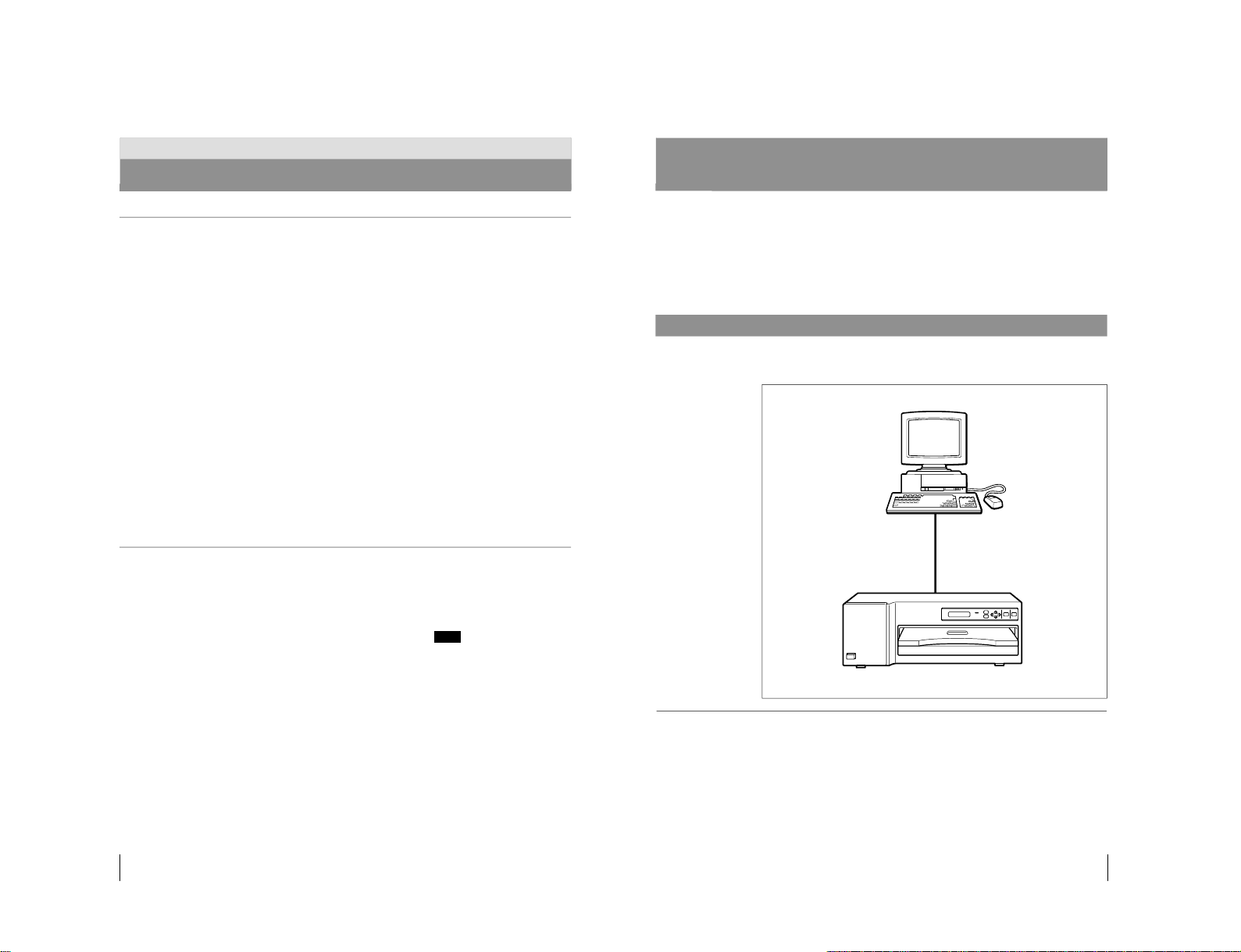
System Configuration
The following shows an example printer system configuration.
About the instruction manual of the printer driver
The instruction manual for the printer driver for the UP-D70A digital color printer
is stored on the CD-ROM supplied with the printer. Substitute this manual for the
printer driver manual for the UP-D70XR.
For detailed information, read the ReadMe file on the CD-ROM.
Computer
Controls the printer
operations.
Digital color printer

1-4 UP-D70XR
6
Introduction
6ALARM indicator (35)
Lights in orange when the ink ribbon or print
paper is exhausted, the paper jams, or another
problem occurs.
7MENU button (13, 24, 26, 28, 29)
Press this button to display or close the
PRINT QTY, COLOR ADJUST, GRAY
ADJUST, GAMMA ADJUST or MARGIN
PRINT menu.
8Cursor control buttons (13, 23, 24, 26,
28, 29)
Use these buttons to increase or decrease a
value and level shown on the menu, or scroll
up and down through a menu.
9STOP button (21)
Press this button to stop printing part-way.
0PRINT button (20, 21, 23)
Press this button to print the image data
stored in the memory of the printer.
!¡ Paper cover (9)
Printouts are ejected here.
!™ Paper tray (9)
Load print paper here. Press the point marked
with PUSH to remove the paper tray.
Location and Function of Parts and Controls
For details, refer to the pages indicated in parentheses.
Front
1UPOWER switch
Press to turn the printer on or off.
2Fan cover (9, 32)
Provided to prevent the printer from dust.
3Ribbon door (15)
Pull the tab (marked with PULL) on the top
on the ribbon door to open it when loading an
ink ribbon cassette.
4PRINT QTY (quantity) button (23)
Press this button to display or close the print
quantity setting menu in the printer window
display.
5Printer window display
Displays the status messages. In menu
operation, the PRINT QTY (print quantity
setting) menu, COLOR ADJUST (printout
adjust) menu, GRAY ADJUST (gray balance
adjust) menu, GAMMA ADJUST (gamma
curve selection) menu or MARGIN PRINT
(margin print setting) menu is displayed.
Also, SCSI device type is dipslayed.
If an error occurs, a corresponding error
message is displayed.
7
Introduction
Rear
1PARALLE DATA IN (Amphenol 36-
pin) (10)
Used to connect a Windows computer via the
parallel interface, using the parallel interface
cable. (not supplied)
2SCSI Connectors (Half pitch 50-pin)
(11)
Used to connect a Windows or Macintosh
computer or another SCSI device, through the
SCSI cable. The other connector is loop-
through connector. If either of the two
connectors is not being used, set the
terminator of the DIP switch to ON.
(See “Setting the DIP Switch”on page 11.)
3DIP switch (11)
Used to set the SCSI ID number and the built-
in terminator to ON or OFF.
(See “Setting the DIP Switch”on page 11.)
4⁄AC IN connector (12)
Used to connect to a wall outlet, using the AC
power cord supplied.
Other manuals for UP-D70XR
1
Table of contents
Other Sony Printer manuals

Sony
Sony DPP-M55 Marketing User manual

Sony
Sony DPP-EX50 User manual

Sony
Sony UP25MD User manual

Sony
Sony SpectaProof UP-D9500 User manual

Sony
Sony UP-D897 User manual

Sony
Sony DPP-FP30 Fall 2005 User manual

Sony
Sony UPA-WU10 User manual

Sony
Sony UP-D75 User manual

Sony
Sony DPP-SV88 User manual

Sony
Sony UP-D897 User manual


