Sony UP-D6500 User manual

Digital Color Printer
3-864-593-11(1)
UP-D6500
UP-D6400
UP-D6300
Operating Instructions Page 2
Mode d’emploi Page 34
Bedienungsanleitung Seite 66
GB
FR
DE
1998 by Sony Corporation

2
English
For the customers in the United Kingdom
WARNING
THIS APPARATUS MUST BE EARTHED
IMPORTANT
The wires in this mains lead are coloured in accordance
with the following code:
Green-and-yellow: Earth
Blue: Neutral
Brown: Live
As the colours of the wires in the mains lead of this
apparatus may not correspond with the coloured
markings identifying the terminals in your plug proceed
as follows:
The wire which is coloured green-and-yellow must be
connected to the terminal in the plug which is marked by
the letter E or by the safety earth symbol Yor coloured
green or green-and-yellow.
The wire which is coloured blue must be connected to the
terminal which is marked with the letter N or coloured
black.
The wire which is coloured brown must be connected to
the terminal which is marked with the letter L or coloured
red.
WARNING
To prevent fire or shock hazard, do not expose the unit
to rain or moisture.
To avoid electrical shock, do not open the cabinet. Refer
servicing to qualified personnel only.
For the customers in the U.S.A.
This equipment has been tested and found to comply
with the limits for a Class A digital device, pursuant to
Part 15 of the FCC Rules. These limits are designed to
provide reasonable protection against harmful
interference when the equipment is operated in a
commercial environment.
This equipment generates, uses, and can radiate radio
frequency energy and, if not installed and used in
accordance with the instruction manual, may cause
harmful interference to radio communications. Operation
of this equipment in a residential area is likely to cause
harmful interference in which case the user will be
required to correct the interference at his own expense.
You are cautioned that any changes or modifications not
expressly approved in this manual could void your
authority to operate this equipment.
The shielded interface cable recommended in this
manual must be used with this equipment in order to
comply with the limits for a digital device pursuant to
Subpart B of Part 15 of FCC Rules.

Table of contents 3
GB
English
Table of Contents
Introduction
Product Features ............................................................... 5
Connection Illustrations ..........................................................6
Part Names and Functions ............................................... 7
Front View ..............................................................................7
Rear View ...............................................................................8
Precautions ........................................................................ 9
Operating Precautions.............................................................9
Installation Precautions...........................................................9
Cleaning ..................................................................................9
Preparation
Supplied Accessories ..................................................... 10
Installing the Ink Ribbon Cassette................................. 11
Installing the Cleaning Rollers ....................................... 13
Installing the Card Tray................................................... 14
Using Optional Accessories........................................... 14
Installing the Auto Card Feeder ............................................15
Installing the Auto Card Stacker...........................................16
Connections..................................................................... 17
Parallel Cable Connection.....................................................17
SCSI Cable Connection (UP-D6500) ...................................18
Setting the SCSI ID...............................................................19
Setting the Terminator ..........................................................19
Printing
Before Printing................................................................. 20
Feeding Method ....................................................................20
Things to Know Before Printing...........................................21
Manual-Feed Printing ...................................................... 22
Printing with the Auto Card Feeder ............................... 23
Precautions During and After Printing .......................... 25

Table of contens
4Table of contents
Appendixes
In Case of Problems ........................................................ 26
About Caution Indicator Lamps............................................26
If parts of the Image do not Print ..........................................27
Changing the Print Head................................................. 28
Specifications .................................................................. 31
Printer Specifications ............................................................31
Options ..................................................................................32

Introduction
Introduction 5
Introduction
Product Features
The UP-D6500, UP-D6400 and UP-D6300 Digital
Color Printers use the dye sublimation thermal transfer
process for duplex printing1) of color and monochrome
characters and graphical computer images on ISO or
JIS standard plastic cards.
These models offer progressively higher levels of
printing quality, as follows:
UP-D6300: Equipped with 4 MB of image memory
and duplex printing capability, this model
connects to the computer’s parallel port.
An automatic card feeder is available as
an option.
UP-D6400: This model adds magnetic read/write and
template memory functions to the features
of the UP-D6300. Options are the same as
for the UP-D6300.
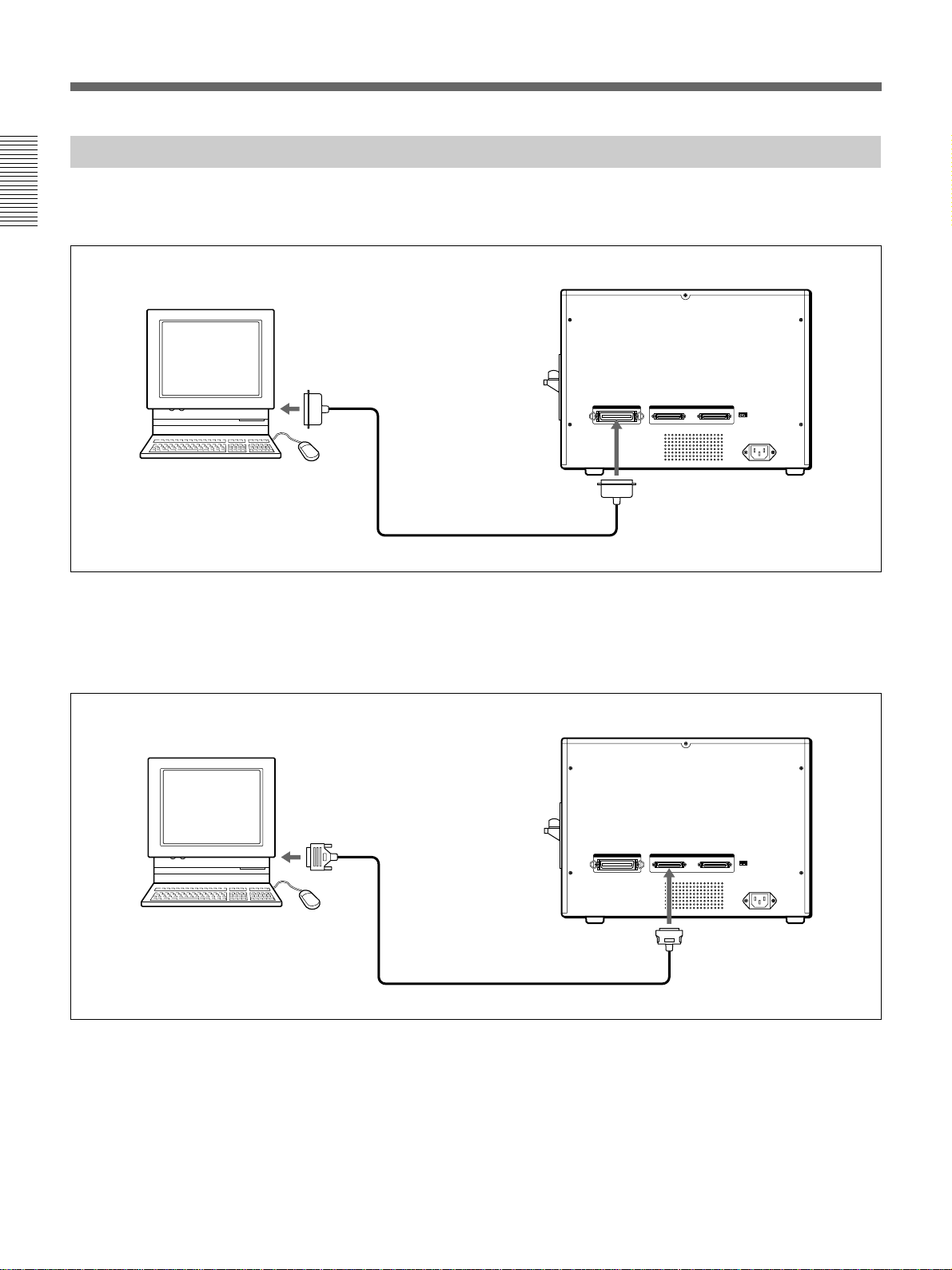
UP-D6500: This model adds Smart Card2) read/write
and SCSI3) interface capabilities to the
features of the UP-D6400. Image memory
is expanded to 8 MB, and data can be
spooled during printing. Two optional
automatic card feeders can be installed
together, and an optional automatic card
stacker can be installed in combination
with the supplied card tray.
This manual describes the common features of the
three models. Features specific to particular models are
described on the applicable pages.
The software supplied with each model lets you easily
combine images and text data to create large quantities
of high-resolution (300 dpi4)), full color ID cards (256-
level grayscale and 16.7 M colors).
Supported Applications
Ask your supplier for information about supported
application programs.
..........................................................................................................................................................................................................
1) Duplex Printing
Printing requires cards that comply with ISO
international standard (ISO7810 ID-1 type) or JIS
standard (JIS X6301-1979).
2) Smart Cards
ISO-standard IC cards incorporating CPU and memory.
This type of card provides better security than the
magnetic stripe type, and offers a wider range of uses.
3) SCSI (Small Computer System Interface)
This is a system standard for connecting peripheral
devices such as printers, hard disk drives, scanners and
other devices with the computer. Up to 7 SCSI devices
(SCSI-compliant peripheral devices) can be connected
by daisy chain to one host computer.
4) dpi (dots per inch)
The unit indicating the number of dots in one inch (25.4
mm).

Introduction
6Introduction
Connection Illustrations
Parallel Cable Connection
The UP-D6300, -D6400 and UP-D6500 connect to the computer by a parallel interface cable.
* The UP-D6300/D6400 do not include a SCSI connector and SCSI ID switch.
SCSI Cable Connection
The UP-D6500 can be connected to the computer by a SCSI cable. When using SCSI connections, other SCSI
devices such as an MO disk drive can be connected in between.
Product Features
Personal Computer UP-D6300/D6400/D6500
Parallel Cable
Use an IEEE-1284 compatible parallel cable
Amphenol 36-pin
Personal Computer UP-D6500
SCSI Cable
Use a SCSI-2 compatible SCSI cable
Half-pitch 50-pin
(pin end)

Introduction
Introduction 7
Part Names and Functions
FrontView
132
45
1POWER Switch
This switch turns the printer on and off. When turned
on, the POWER ON lamp on the indicator panel lights
green.
2Front Door
The ink ribbon cassette and cleaning roll holder are
installed behind this door. Pull on both sides of the
door to open it.
ba c
d
e
aInk Ribbon Holder
An ink ribbon (sold separately) installs in the ink
ribbon holder.
bBad Card Stacker
Bad cards are rejected here. Always remove any bad
cards before printing, and when the ALARM lamp
blinks.
cCleaning Roller Cover
The cleaning rollers are installed behind this cover. To
open it, pull where it says PULL OPEN.
dCleaning Roller Holder
The cleaning rollers install on this holder. Pull the
knob to remove it.
eCleaning Rollers
The cleaning rollers are supplied with the printer.
When a card enters the printer, it passes between these
rollers to remove any dust from the card, so the rollers
should always be installed. Wash the rollers
periodically with water (page 27).
3Indicator Panel Lamps
The panel lamps indicate the status of the printer.
fghijk
POWER ON ALARM RIBBON CARD PRINT READY
fPOWER ON lamp (green)
This lamp is lit when the power is on.
gALARM lamp (orange)
This lamp blinks when an error occurs, and lights
steadily when a fatal error occurs.
hRIBBON lamp (orange)
This lamp blinks when the ink ribbon supply is low,
and lights steadily when the ink ribbon reaches the
end.
iCARD lamp (orange)
This lamp lights when the optional automatic card
feeder is installed. During manual-feed operation, this
lamp lights when the printer is waiting for a card.
jPRINT lamp (green)
This lamp lights while printing. During manual-feed
operation, this lamp blinks when the printer is waiting
for a card to be inserted.
kREADY lamp (green)
This lamp blinks during warm-up, and when data is
being sent to the printer. This lamp light steadily when
the printer is ready to print.

Introduction
8Introduction
4Card Tray
Printed cards are ejected here. 5Card Insertion Slot
Insert a card here for manual feed. The optional
automatic card feeder can also be installed here.
Part Names and Functions
Rear View
6 87
9
6Parallel Interface Connector
Connect the parallel port of the controlling computer
here using a parallel interface cable.
7SCSI Connectors (UP-D6500 only)
The SCSI connectors on the UP-D6500 can be used to
connect this model to the controlling computer and
other peripheral devices via a SCSI cable. The second
connector can be used to connect other SCSI devices
with this printer. However, if one of the connectors is
not used, set the terminator switch (leftmost SCSI ID
switch 8) to the ON position.
8SCSI ID and SCSI Terminator switch
(UP-D6500 only)
This switch sets the SCSI ID for the printer. Also, if no
other SCSI devices are connected to the printer, so that
one of the SCSI connectors is unused, set the SCSI
terminator switch ON.
9AC IN (Power Input) Socket
The supplied AC power cord connects here.

Introduction
Introduction 9
Precautions
Operating Precautions
Power Supply
Connect only to the specified power source (120 or
240 VAC, 50/60 Hz).
Handle the Power Cord Carefully
Do not bend the cord sharply or place heavy objects on
it. The cord could be damaged and cause a fire or
electric shock. Do not use a damaged cord.
Avoid Ingress of Foreign Objects
Do not spill any liquids or drop any flammable or
metallic objects into the printer. Operating the printer
with a foreign object inside may cause fire, electric
shock or damage.
To Avoid Electric Shock
Never remove the outer cabinet. Touching internal
components may cause electric shock and presents
other dangers.
In Case of Abnormal Operation
In the event of an unusual sound or smell, or if smoke
appears or a foreign object falls into the printer, turn
off the power and contact your nearest Sony Service
Center.
If not Using for a Long Time
Turn off the power and unplug the power cord from
the outlet.
About Transporting
Remove all attached accessories before transporting
the printer. Transporting with accessories connected
may result in damage.
About Card Stock
Use cards that comply with ISO international standard
(ISO7810 ID-1 type) or JIS standard (JIS X6301-
1979).
Notes
•Use only clean cards, with no debris, dirt or other
adhering matter.
•Some card materials may not be suitable. Contact
your supplier for details.
Installation Precautions
Do not install or store the printer in the following
conditions:
•Exposed to direct sunlight
•In humid locations
•In very hot or cold locations
•Where it might be exposed to heavy vibration
•Dusty locations
•On an unstable surface
•Avoid blocking the vent on the rear, as damage could
result.
About Condensation
If the printer is moved from a cool place to a warm
humid place, moisture may condense inside. Operating
the printer in this condition could cause a malfunction
and damage. Therefore, if any possibility of
condensation is suspected, the printer should be turned
off and allowed time to reach equilibrium with the
environment.
Cleaning
When the cabinet becomes dirty, wipe it with a cloth
moistened with water or a solution of synthetic
detergent (after wringing out any excess liquid). Do
not use thinner, cleaning fluid, alcohol or a chemically
treated cloth, as these could damage the cabinet finish.
Vent

Preparation
10 Preparation
Preparation
Supplied Accessories
Make certain you have received the following
accessories: Operating Manual (1)
Floppy Diskette (1)
Notes
•The packing materials are needed when transporting
the printer, so we suggest you keep them.
•Before printing, be sure to remove the packing
material that immobilizes the head for transport.
Card Tray (1) Cleaning Roller Holder (1)
Ink Ribbon Holder (1)
AC Power Plug Adapter (1) AC Power Cord (1)

Preparation
Preparation 11
Installing the Ink Ribbon Cassette
This procedure describes how to install the ribbon
cassette in the printer.
Before beginning, obtain the required ink ribbon (sold
separately). The following types of ink ribbon are
available:
Color ink ribbon 5UPR-6040: 3-color CMY and
laminate
Color ink ribbon 5UPR-6080: 4-color CMYK and
laminate
Black ink ribbon UPR-6025: black only
•The 5UPR-6040/6080 ribbons provide lamination
along with color printing.
The color ink ribbon package consists of five pieces
in one set. One roll of 5UPR-6040 can print about
250 single-sided cards, and one roll of 5UPR-6080
can print about 200 single-sided cards.
•The UPR-6025 ribbon package consists of one unit
which prints black only. About 1,000 single-sided
cards can be printed.
1Hold both sides of the front door, and pull it down
to open.
2To change the ink ribbon, press on the part marked
PUSH to remove the ink ribbon holder.
When installing an ink ribbon in the printer the
first time, skip this step and proceed to step 4.
Note
Do not touch the inside of the ink ribbon holder
compartment. The print head inside the printer may
be very hot.
3When changing the ink ribbon, remove the used
ribbon from the ribbon holder.
When installing an ink ribbon in the printer the
first time, skip this step and proceed to step 4.
4Install an ink ribbon in the ink ribbon holder.
1Remove take-up spool 2Remove supply spool
Ink ribbon holder
Barcode ring
1Install the ink ribbon
supply spool.
2Install the take-up spool.
Ink ribbon

Preparation
12 Preparation
5Take up any slack in the ribbon.
To avoid damage to the ribbon during installation,
take up the slack.
6Insert the ink ribbon holder into its installation slot,
and push until it stops.
7Confirm that the installation was done correctly,
and close the front door.
Handling Ink Ribbons
•Do not reuse ink ribbons.
•Do not touch the surface of a ribbon, or store it in a
dusty place. Fingerprints and dust may cause
degraded printing.
Storing Ink Ribbons
•Do not store ribbons in hot or humid places.
•To preserve a partially used ribbon, save it in the
humidity-resistant bag in which it was originally
supplied.
If a Ribbon Breaks
You can repair a broken ribbon with plastic tape so
you can use the remaining unused portion.
Installing the Ink Ribbon Cassette
Turn the spools alternately
to remove slack.
Repair with plastic tape
Take up slack ribbon

Preparation
Preparation 13
Installing the Cleaning Rollers
This procedure describes how to install the cleaning
rollers in the printer.
1Hold both sides of the front door, and pull it down
to open.
2Pull on the cleaning roller cover marked PULL
OPEN to remove the cover.
3Install two cleaning rollers into the cleaning roller
holder.
Be careful to avoid touching the roller surfaces, as
printing could be degraded.
When installing cleaning rollers in the printer the
first time, skip this step and proceed to step 4.
4Insert the cleaning roller holder into the printer,
and push it until it stops.
Align the top and bottom guides with the rails
when inserting.
5Install the cleaning roller cover removed in step 2.
6Close the front door.
Note
After using the cleaning rollers for a long time, their
cleaning ability will be degraded, causing colors to fail
to transfer properly to the printout. To avoid this, wash
the cleaning rollers each time after printing about 200
cards (page 27).
Insert the roller axles into the slots.
Guide
Rail
Insert the bottom edge of the
cover first, then push the top
edge.

Preparation
14 Preparation
Installing the CardTray
Printed cards are ejected into the card tray. Install the
card tray with this procedure.
When installing the optional Auto Card Stacker, the
card tray should be installed after the Auto Card
Stacker (page 16).
1Insert the card tray hook into the insertion slot on
the printer.
2Pull the card tray down.
Note
Be sure to pull the card tray down completely, or cards
may fail to eject and jam in the printer.
Hook
Card Tray
Pull down
Using Optional Accessories
Optional accessories for these printer models include
the UPA-6003 Auto Card Feeder to automatically feed
cards to the printer when printing, and the UPA-6002
Auto Card Stacker to receive printed cards from the
printer.
One Auto Card Feeder can be installed on the UP-
D6400/D6300, and up to two Auto Card Feeders and
one Auto Card Stacker can be installed on the UP-
D6500. The supplied card tray can also be installed
when the Auto Card Stacker is installed.
Option Option
Supplied
card tray Supplied
card tray
UP-D6400/D6300/D6500 UP-D6500
UPA-6003 UPA-6003UPA-6002
Auto Card Feeder
UPA-6003
Auto Card Stacker Auto Card Feeder
(1st Unit) Auto Card Feeder
(2nd Unit)
Continuously prints up to about 125 ISO
standard 0.76-mm-thick cards. Continuously prints up to about 250 ISO
standard 0.76-mm-thick cards.

Preparation
Preparation 15
Installing the Auto Card Feeder
Note
Always turn off the power to the printer when
installing or removing options.
1Remove the manual guide for the card insertion
slot while pushing up on the knob.
2Push down on the upper knob and remove the
connector cover.
3Align and insert the connector and guide pins on
the Auto Card Feeder to the connector and guide
holes on the printer.
Remove the upper edge first,
then the lower edge
Remove the upper edge first,
then the lower edge
Align the connectors
Align the guide holes
4Push the Auto Card Feeder so the connectors mate
firmly.
Installing a Second Feeder
A second Auto Card Feeder can be installed on the
UP-D6500. The second feeder installs on the outer side
of the first feeder, using the same procedure.
Removing the Feeder
To remove the feeder, open the feeder cover and push
down on the locking level while separating the feeder
from the printer.
Push firmly

Preparation
16 Preparation
Installing the Auto Card Stacker
Using Optional Accessories
1Push down on the upper knob and remove the
connector cover.
2Align and insert the connector and guide pins on
the Auto Card Stacker to the connector and guide
holes on the printer.
3Push the Auto Card Stacker so the connectors mate
firmly.
Also Installing the Supplied Card Tray
Install the supplied card tray after installing the Auto
Card Stacker. The card tray installs on the outside of
the Auto Card Stacker, using the same procedure as for
installing it on the printer (page 14).
Removing the Stacker
To remove the stacker, open the stacker cover and
push down on the locking level while separating the
stacker from the printer.
Remove the upper edge first,
then the lower edge
Align the connectors
Align the guide holes
Push firmly

Preparation
Preparation 17
Connections
The following examples show the connection of the
system to print cards. The UP-D6500/D6400 and
D6300 are equipped with a parallel connector for
connecting to the computer with a parallel cable. The
D6500 is also equipped with a SCSI connector, which
can be used with a SCSI cable instead of the parallel
connection.
Parallel Cable Connection
Notes
•Turn off the power to all devices when making connections.
•Connect the power cords last.
•Insert the parallel data cable connector firmly, as far as it will go.
•The parallel cable should be no longer than 3 meters, and conform to the Centronics specification. However, the
type of connectors on the parallel cable depends on the computer and other peripheral devices being connected.
Refer to the operating manuals for the devices for details.
•To use the high speed drive mode (ECP mode), the cable should comply with IEEE1284, such as the Hewlett
Packard model C2950A.
•Do not use the SCSI interface when using the parallel interface.
1) Use a parallel cable that complies with IEEE-1284. Refer also to the computer operating manual for the type of parallel
cable to use.
* The UP-D6300 and D6400 do not have SCSI connectors or a SCSI ID switch.
Personal Computer Clip bail locks on both sides UP-D6300/D6400/D6500
To parallel
connector
Parallel cable1) To parallel
connector To power outlet
To AC IN

Preparation
18 Preparation
SCSI Cable Connection (UP-D6500)
Notes
•Turn off the power to all devices when making connections.
•Connect the power cords last.
•Up to seven peripheral devices can be connected to the SCSI bus.
•Refer to the operating manual for each device for details about peripheral device connections.
•Insert the SCSI cable connectors firmly, as far as they will go.
•The total length of the SCSI cable connected to one host computer should be no more than three meters.
•When only the printer is connected to one host computer, the SCSI cable length should be no more than one
meter.
•Do not use the parallel interface when using the SCSI interface.
1) Refer to the computer operating manual for the type of SCSI cable to use. When connecting other SCSI devices, refer
also to the manuals supplied with those devices. Use a cable compatible with the SCSI2 standard.
2) The SCSI bus allows connection of other SCSI devices by daisy chain between the computer and printer, and after the
printer. Refer to the operating manuals of those devices for the settings on those devices.
3) For SCSI connections, the SCSI ID should be set by the SCSI ID switch (page 19). Also, if one of the SCSI connectors
on the printer is not used, set the leftmost (terminator) switch on the SCSI ID switches to ON (page 19).
Connection
Personal Computer
UP-D6500
To SCSI
connector
To power outlet
To AC IN
SCSI ID
SCSI cable1)
To SCSI connector
Connects to other devices, if needed.2)

Preparation
Preparation 19
Setting the SCSI ID
Up to seven SCSI devices can be connected to the
SCSI bus by daisy chaining. Each SCSI device is
recognized by its ID number, from 0 to 7.
Turn off the power to the printer, and set the printer ID
number with the SCSI ID switches on the rear, so that
it is unique from any other SCSI device. When shipped
from the factory, the SCSI ID is set to “2”.
The SCSI ID number is set by the combination of three
SCSI ID switch settings.
1
124ON
TERMINATOR
000OFF 432
SCSI ID
ID=0 ID=1 ID=2 ID=3 ID=4 ID=5 ID=6 ID=7
Switch 4 OFF ON OFF ON OFF ON OFF ON
Switch 3 OFF OFF ON ON OFF OFF ON ON
Switch 2 OFF OFF OFF OFF ON ON ON ON
Note
When setting the SCSI ID, be careful not to duplicate
the number of another device on the SCSI bus. The ID
must be unique for each device.
Setting theTerminator
The leftmost switch of the SCSI ID switches is the
terminator switch. Turning this switch on enables the
internal SCSI terminator.
If either of the SCSI connectors is not used in the
installation, turn the terminator switch ON.
The SCSI ID consists of the sum of the ID
number of each switch that is turned on.
Switch 4
Switch 3
Switch 2

Printing
20 Printing
Printing
Before Printing
Confirm the feeding method and precautions before printing.
Feeding Method
The printing feeding method for cards depends on
whether the optional Auto Card Feeder is installed.
Before beginning, confirm the feeding method to be
used for printing.
Standard Case
If the optional Auto Card Feeder is not installed, feed
the cards manually one at a time after sending the print
command.
Auto Card Feeder Case
If cards are placed in the Auto Card Feeder, the cards
are fed to the printer after sending the print command.
If a second Auto Card Feeder is installed on the UP-
D6500, cards in the first Auto Card Feeder are fed
first, followed by those in the second Feeder when the
first is empty.
Cards can also be fed manually at the card insertion
slot of the Auto Card Feeder. However, do not insert
cards that are a different size from those in the Auto
Card Feeder, or a jam may result.
Note
Cards with fingerprints or dirt on their surface may
degrade printing. To avoid touching the surface, insert
a card by holding it at the edges.
We recommend using the Auto Card Feeder to
minimize the need to touch the cards.
Feed manually after executing print command
Cards are fed automatically at print time
This manual suits for next models
2
Table of contents
Languages:
Other Sony Printer manuals

Sony
Sony FilmStation UP-DF750 User manual

Sony
Sony UP-D6300 User manual

Sony
Sony CVP-M3 User manual

Sony
Sony CCP-13B User manual

Sony
Sony DPP-FP85 User manual

Sony
Sony UP-51MDP User manual

Sony
Sony UP-51MD User manual

Sony
Sony DPP-FP30 Fall 2005 User manual

Sony
Sony UP55MD User manual

Sony
Sony DPP FP70 - Picture Station Photo Printer User manual

Sony
Sony PVP-MSH User manual

Sony
Sony UP-CR10L User manual

Sony
Sony UP-D75 User manual

Sony
Sony DPP-FP50 Fall 2005 User manual

Sony
Sony UP-X898MD User manual

Sony
Sony DPP-F700 - Digital Photo Printer/frame Manual

Sony
Sony DPP-EX50 User manual

Sony
Sony UP-2100 User manual

Sony
Sony DPP-SV55 User manual

Sony
Sony DPP-SV55 User manual