Sony UP-DR200 User manual

SERVICE MANUAL
1st Edition
DIGITAL PHOTO PRINTER
UP-DR200

UP-DR200
!WARNING
This manual is intended for qualified service personnel only.
To reduce the risk of electric shock, fire or injury, do not perform any servicing other than that
contained in the operating instructions unless you are qualified to do so. Refer all servicing to
qualified service personnel.
!WARNUNG
Die Anleitung ist nur für qualifiziertes Fachpersonal bestimmt.
Alle Wartungsarbeiten dürfen nur von qualifiziertem Fachpersonal ausgeführt werden. Um die
Gefahr eines elektrischen Schlages, Feuergefahr und Verletzungen zu vermeiden, sind bei
Wartungsarbeiten strikt die Angaben in der Anleitung zu befolgen. Andere als die angegeben
Wartungsarbeiten dürfen nur von Personen ausgeführt werden, die eine spezielle Befähigung
dazu besitzen.
!AVERTISSEMENT
Ce manual est destiné uniquement aux personnes compétentes en charge de l’entretien.Afin
de réduire les risques de décharge électrique, d’incendie ou de blessure n’effectuer que les
réparations indiquées dans le mode d’emploi à moins d’être qualifié pour en effectuer d’autres.
Pour toute réparation faire appel à une personne compétente uniquement.

1
UP-DR200
Table of Contents
Manual Structure
Purpose of this manual ................................................................. 3
Related manuals ........................................................................... 3
1. Service Overview
1-1. Precaution when Transporting the Unit ..........................1-1
1-2. Board Location ...............................................................1-1
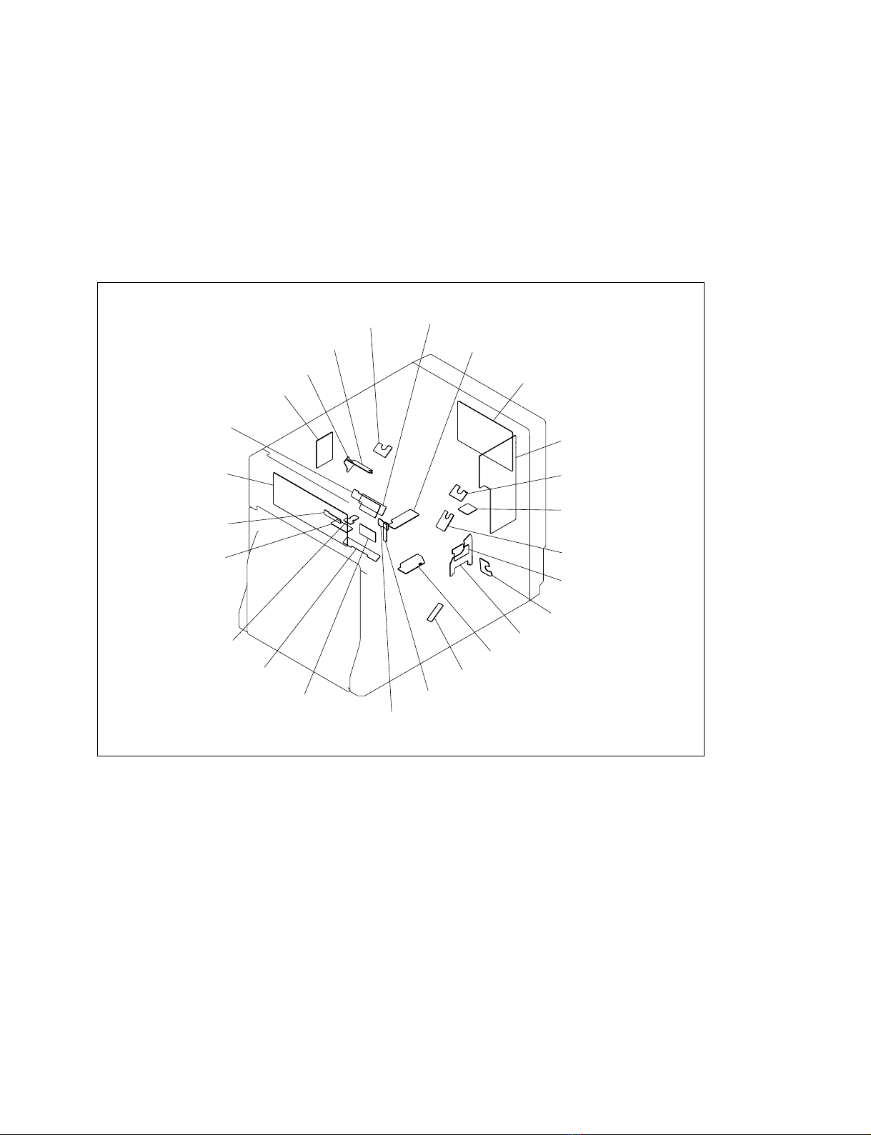
1-3. Main Parts and Sensor Location .....................................1-2
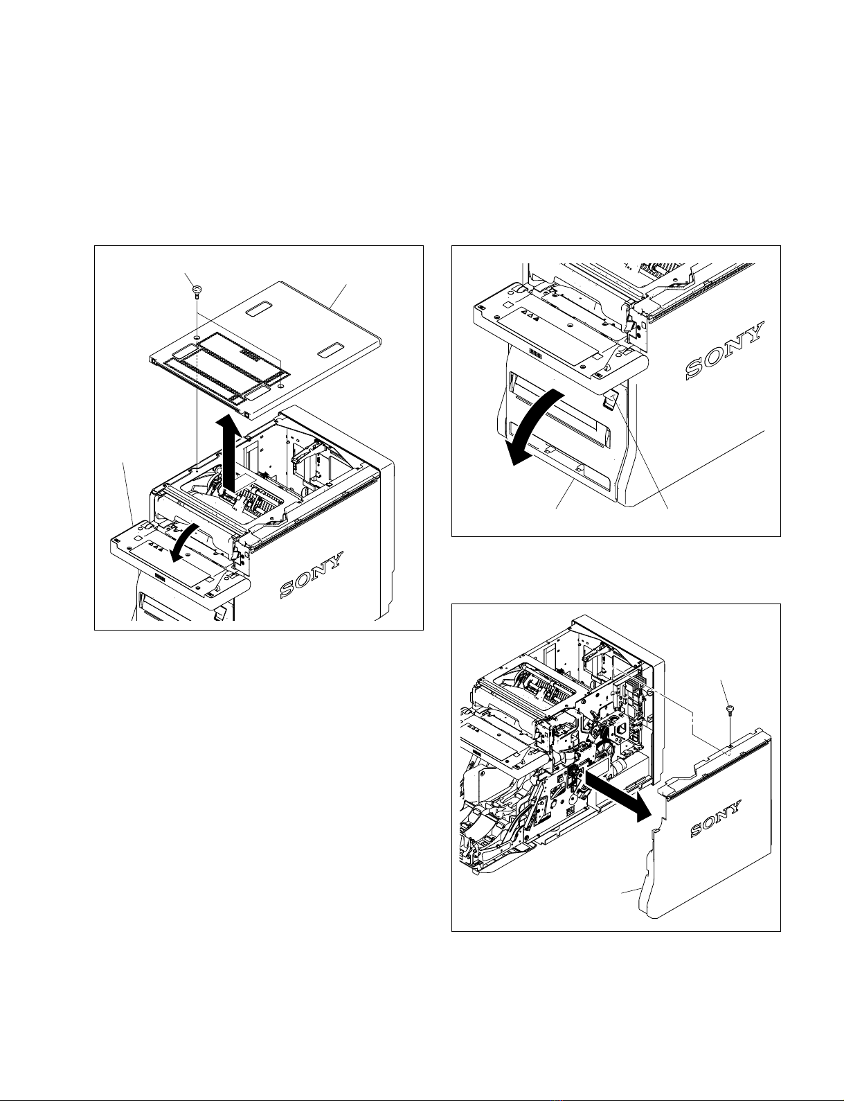
1-4. Removing/Installing the Cabinet ....................................1-3
1-4-1. Top Panel Assembly..............................................1-3
1-4-2.
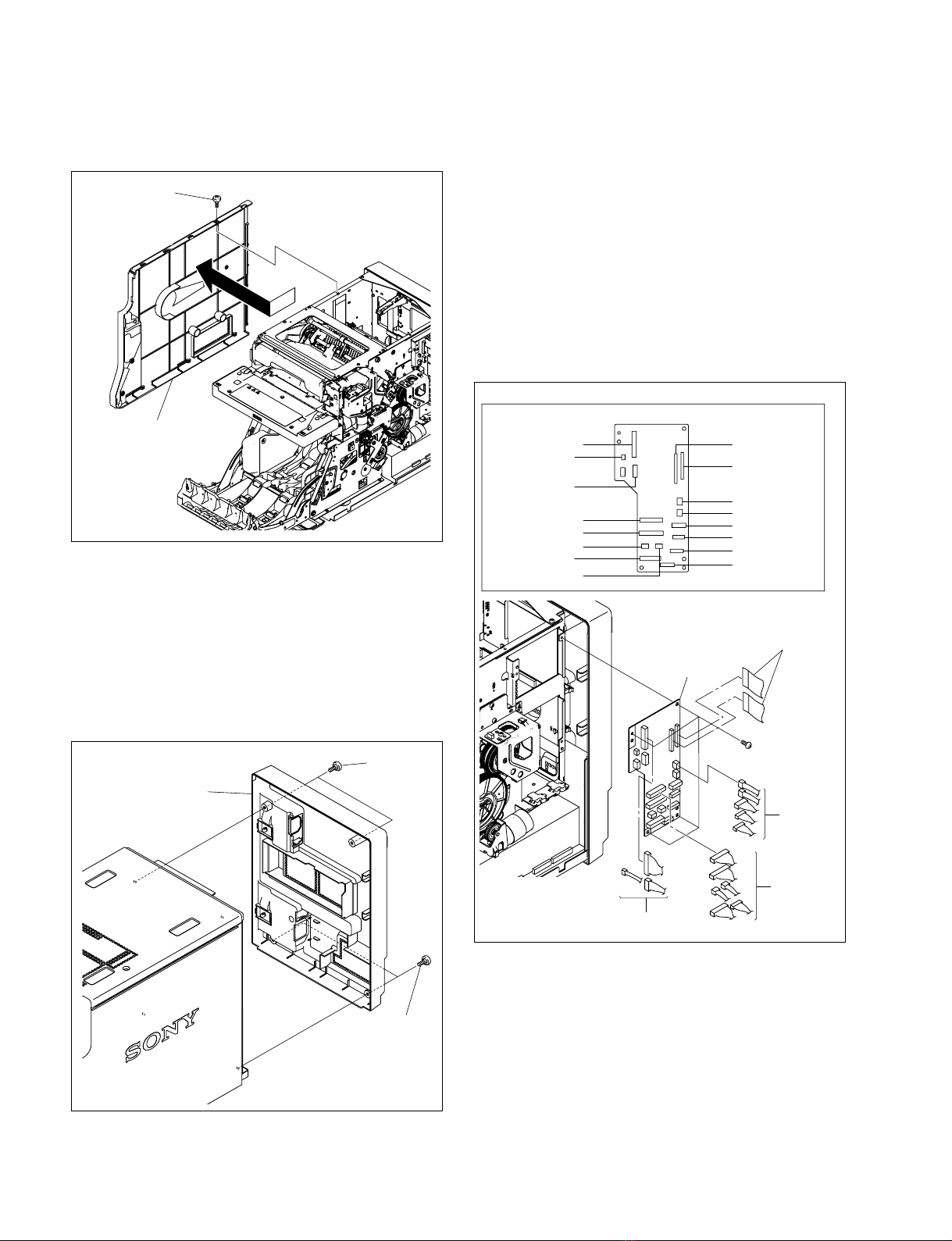
Side Panel (R) Assembly/Side Panel (L) Assembly ...
1-3
1-4-3. Rear Panel Assembly ............................................1-4
1-5. Replacing the Board .......................................................1-4
1-5-1. MEC-36 Board ......................................................1-4
1-5-2. MA-168 Board ......................................................1-5
1-5-3. KY-632 Board .......................................................1-5
1-5-4. SE-934 Board ........................................................1-6
1-6. Replacing the Main Parts................................................1-6
1-6-1. Ribbon Door Assembly .........................................1-6
1-6-2. Paper Door Assembly............................................1-7
1-6-3. Paper Holder (Main) Assembly.............................1-8
1-6-4. Ribbon Door Lock Assembly................................1-9
1-6-5. Cutter Unit.............................................................1-9
1-6-6. Pinch Motor Assembly ..........................................1-9
1-6-7. Supply Drive Assembly ......................................1-10
1-6-8. Takeup Drive Assembly......................................1-11
1-6-9. Paper Eject Guide Assembly ...............................1-12
1-6-10. Paper Holder Stay Assembly...............................1-12
1-6-11. Vertical Guide Assembly ....................................1-13
1-6-12. Return Guide Assembly ......................................1-15
1-6-13. Platen Roller ........................................................1-16
1-6-14. Capstan Roller .....................................................1-17
1-6-15. Pinch Roller .........................................................1-18
1-6-16. Stepping Motor....................................................1-19
1-6-17. Thermal Head ......................................................1-19
1-6-18. Head Unit Assembly ...........................................1-20
1-6-19. Pinch Cam/Head Cam .........................................1-21
1-6-20. Switching Regulator ............................................1-22
1-6-21. DC Fan (for inside) .............................................1-23
1-6-22. DC Fan (thermal head) ........................................1-23
1-6-23. Filter ....................................................................1-24
1-7. Cleaning the Interior .....................................................1-24
1-8. Recommended Power Cord ..........................................1-27
1-9. Unleaded Solder............................................................1-27
2. Adjustment for Parts Replacement
2-1. Thermal Head .................................................................2-1
2-1-1. Thermal Head Position Adjustment ......................2-2
2-2. Ribbon Mark Sensor (LE-352/SE-934 Board) ...............2-3
2-3. Paper FG Sensor (SE-935 Board)...................................2-3
2-4. MA-168 Board ................................................................2-4
3. Mechanical Operation Description
3-1. Mechanical Operation Flow ...........................................3-1
3-1-1. Power ON (or Door Open/Close)..........................3-1
3-1-2. Print Operation ......................................................3-2
3-2. Main Parts Constitution ..................................................3-3
3-3. Decurl Mechanism ..........................................................3-4
3-4. Ribbon Drive Mechanism...............................................3-5
3-5. Mechanical Operation.....................................................3-7
4. Circuit Description
4-1. Board Configuration .......................................................4-1
4-1-1. MA-168 Board ......................................................4-1
4-1-2. KY-632 Board .......................................................4-1
4-1-3. MEC-36 Board ......................................................4-1
4-2. Motor Control .................................................................4-1
4-2-1. Stepping Motor Driving ........................................4-1
4-2-2. Head Motor Driving ..............................................4-2
4-2-3. Pinch Motor Driving .............................................4-2
4-2-4. Takeup Motor Driving ..........................................4-2
4-2-5. Supply Motor Driving ...........................................4-2
4-2-6. Cutter Motor Driving ............................................4-2
4-3. Fan and Plunger Control .................................................4-2
4-3-1. Driving of Thermal Head Cooling Fan .................4-2
4-3-2. Driving of In-storage Cooling Fan ........................4-3
4-3-3. Plunger Driving .....................................................4-3
4-4. IC Tag Control ................................................................4-3
4-5. Sensor LED Control .......................................................4-3
4-5-1. Ribbon Mark Sensor LEDs ...................................4-3
4-5-2. Other Sensor LEDs................................................4-4
4-6. Sensor Detection .............................................................4-4
4-6-1. Pinch Home Sensor and Pinch Position Sensor ....4-4
4-6-2. Head Home Sensor and Head Position Sensor......4-4
4-6-3. Head arm Home Sensor and
Head Arm Position Sensor ....................................4-5

2UP-DR200
8. Block Diagrams
Overall ............................................................................8-1
9. Frame Wiring
Frame Wiring..................................................................9-2
4-6-4. Cutter Home Sensor and Cutter Position Sensor ..4-5
4-6-5. Paper Size Sensor ..................................................4-5
4-6-6. Paper Sensor ..........................................................4-5
4-6-7. Ribbon Door Sensor ..............................................4-6
4-6-8. Paper Door Sensor.................................................4-6
4-6-9. Paper Pass Sensor ..................................................4-6
4-6-10. Paper Edge Sensor.................................................4-6
4-6-11. Ribbon Mark Sensor..............................................4-7
4-6-12. Paper FG Sensor ....................................................4-7
4-6-13. Takeup FG Sensor .................................................4-7
4-6-14. Supply FG Sensor..................................................4-7
4-7. Temperature Detection ...................................................4-7
4-7-1. Head Thermister ....................................................4-7
4-7-2. Room Thermister...................................................4-7
4-7-3. Platen Thermister ..................................................4-7
5. Service Mode
5-1. Start .................................................................................5-1
5-2. Configuration ..................................................................5-1
5-3. INFORMATION Menu ..................................................5-1
5-4. PRINT Menu ..................................................................5-3
5-5. SETUP Menu ..................................................................5-4
5-6. MANUAL MECHA Menu .............................................5-4
6. Troubleshooting
6-1. Error Display ..................................................................6-1
6-2. Error Contents and Possible Causes ...............................6-2
6-3. Error Log (ERROR LOG) Information ..........................6-9
6-4. Printing Image Defects .................................................6-10
7. Spare Parts
7-1. Notes on Repair Parts ........................................................ 1
7-2. Exploded Views ................................................................. 2
7-3. Packing Materials & Supplied Accessories ..................... 23

3
UP-DR200
Manual Structure
Purpose of this manual This manual is the Service Manual of the Digital Photo Printer UP-DR200.
This manual contains the installation, service overview, adjustment for parts replace-
ment, mechanical operation description, circuit description, service mode, trouble-
shooting, spare parts, block diagrams, and frame wiring.
The service of this unit is basically performed by the replacement of board.
Therefore, the schematic diagram, board layout and electrical parts list are not
contained.
Related manuals In addition to this Service Manual , the following manual is provided.
..
..
.Operating Instructions (CD-ROM)
Part No.: 3-297-457-0X
This manual describes the information required for the actual management and
operation of this unit.
..
..
.“Semiconductor Pin Assignments” CD-ROM (Available on request)
This “Semiconductor Pin Assignments” CD-ROM allows you to search for
semiconductors used in Broadcast and Professional equipment.
Part number: 9-968-546-06


1-1
UP-DR200
Section 1
Service Overview
1-1. Precaution when Transporting the Unit
When transporting this unit, be sure to remove the ink ribbon and printing paper from the unit.
1-2. Board Location
CN-3049 board
CN-3048 board
SE-927 board
SU-136 board
KY-632 board
SE-933 board
SE-929 board
LE-350 board SE-930 board
SE-932 board
SE-934 board
LE-352 board
SU-137 board
SU-135 board
SE-936 board
SU-138 board
SE-935 board
SE-926 board
SE-928 board
SU-134 board
SE-931 board
LE-351 board
MEC-36 board
MA-168 board
SE-937 board

1-2 UP-DR200
1-3. Main Parts and Sensor Location
Head (L) motor
Stepping motor
Thermal head
Takeup motor
Switching regulator
Head (R) motor
Supply motor
Cutter unit
Pinch motor
DC fans (thermal head)
DC fans (for inside)
Head position sensor
Paper edge sensor
Paper size sensor Ribbon door sensor
Paper path sensor
Ribbon mark sensor
Takeup sensor
Paper FG sensor
Pinch position sensor
Head arm position sensor
Paper door sensor
Supply sensor

1-3
UP-DR200
1-4. Removing/Installing the Cabinet
1-4-1. Top Panel Assembly
1. Open the ribbon door assembly.
2. Remove the two stepped screws, then remove the top
panel assembly in the direction of the arrow.
3. Attach the top panel assembly in the reverse order of
steps 1 and 2.
Ribbon door
assembly
Stepped screws Top panel assembly
1-4-2. Side Panel (R) Assembly/Side Panel
(L) Assembly
1. Remove the top panel assembly.
(Refer to Section 1-4-1.)
2. Release the eject button, then open the paper door
assembly.
3. Remove the stepped screw, then remove the side panel
(R) assembly in the direction of the arrow.
Eject buttonPaper door assembly
Side panel (R) assembly
Stepped screw

1-4 UP-DR200
Stepped screw
Side panel (L) assembly
4. Remove the stepped screw, then remove the side panel
(L) assembly in the direction of the arrow.
5. Attach the side panel (R) assembly and side panel (L)
assembly in the reverse order of steps 1 to 4.
1-4-3. Rear Panel Assembly
1. Remove the four stepped screws, then remove the rear
panel assembly.
2. Attach the rear panel assembly in the reverse order.
Stepped
screws
Stepped
screws
Rear panel assembly
MEC-36 board
BVTT3 x6
Harnesses
Harnesses
Flexible flat cables
Harnesses
CN10
MEC-36 board Side A
CN7 CN2
CN17
CN18
CN14
CN5
CN8
CN4
CN3
CN15
CN16
CN12
CN1
CN13
CN9
1-5. Replacing the Board
1-5-1. MEC-36 Board
1. Remove the top panel assembly.
(Refer to Section 1-4-1.)
2. Remove the side panel (R) assembly.
(Refer to Section 1-4-2.)
3. Disconnect the flexible flat cables and harnesses from
all connectors on the MEC-36 board.
4. Remove the four screws, then remove the MEC-36
board.
5. Install the MEC-36 board in the reverse order of steps
1 to 4.

1-5
UP-DR200
1-5-2. MA-168 Board
n
Before replacing the MA-168 board, be sure to check
Section 2-4.
1. Remove the rear panel assembly.
(Refer to Section 1-4-3.)
2. Disconnect the flexible flat cables and harnesses from
all connectors on the MA-168 board.
3. Remove the screw (PS3 x 4).
4. Remove the four screws (BVTT3 x 6), then remove
the MA-168 board in the direction of the arrow.
5. Install the MA-168 board in the reverse order of steps
1 to 4.
BVTT3 x6
Flexible flat cables
MA-168 board
PS3 x4
Harness
MA-168 board Side A
CN401
CN902
CN903
CN901 CN701
1-5-3. KY-632 Board
1. Open the ribbon door assembly. (Refer to Section 1-4-1.)
2. Remove the five screws (BTP3 x 10), then remove the
rear cover (RD) assembly.
3. Remove the two screws (BTP3 x 10), then remove the
ribbon door (front) assembly.
4. Close the ribbon door assembly.
5. Disconnect the flexible flat cable from the connector
(CN101) on the KY-632 board.
6. Remove the three screws (BVTT3 x 6), then remove
the KY-632 board.
7. Install the KY-632 board in the reverse order of steps 1
to 6.
BTP
3 x10
BTP
3 x10
Rear cover (RD) assembly
Ribbon door (front) assembly
BVTT
3 x6
KY-632 board
CN101
Flexible flat cable
Ribbon door
assembly

1-6 UP-DR200
Harness
BVTT3 x6
CN421
Heat sink block
assembly
SE-934 board
Heat sink
block assembly
Maintenance
arm assembly
Hook here
PSW
3 x 6
BVTT
3 x 6
1-5-4. SE-934 Board
n
When replacing the SE-934 board, be sure to check
Section 2-2.
1. Remove the top panel assembly. (Refer to Section 1-4-1.)
2. Remove the two screws (BVTT3 x6) and two screws
(PSW3 x6), then place the heat sink block assembly
upward and hook it on the maintenance arm assembly.
3. Remove the screw, then remove the SE-934 board.
4. Disconnect the harness from the connector (CN421)
on the SE-934 board.
5. Install the SE-934 board in the reverse order of steps 1
to 4.
Flexible flat cable
Paper eject
guide cover
Top chassis
MA-168
board
CN701
BVTT3 x6
BVTT3 x6
Flat clamps
Flat clamp
Hook
Ribbon door
lock cover
1-6. Replacing the Main Parts
1-6-1. Ribbon Door Assembly
n
When removing the ribbon door assembly, be careful not
to damage the flexible flat cable.
1. Remove the cabinet. (Refer to Section 1-4.)
2. Open the ribbon door assembly.
3. Remove the two screws, then remove the paper eject
guide cover in the direction of the arrow.
4. Disconnect the flexible flat cable from the connector
(CN701) on the MA-168 board.
5. Remove the four flat clamps.
6. Remove the hook, then remove the ribbon door lock
cover.

1-7
UP-DR200
7. Remove the four screws, then remove the ribbon door
assembly in the direction of the arrow.
8. Remove the four hooks, then remove the inner cover
(front).
9. Attach the ribbon door assembly in the reverse order
of steps 1 to 8.
n
When attaching the paper eject guide cover, attach it
so that the discharging brush is placed under the
ribbon roller (CH).
BVTT3 x6
BVTT3 x6
BVTT3 x6
Ribbon door
assembly
Inner cover
(front)
Hooks
Hooks
Discharging brush
Paper eject guide cover
Ribbon roller (CH)
1-6-2. Paper Door Assembly
1. Remove the top panel assembly.
(Refer to Section 1-4-1.)
2. Remove the side panel (R) assembly/side panel (L)
assembly. (Refer to Section 1-4-2.)
3. Remove the two snap rings (E3.0), then remove the
paper arm levers.
4. Remove the two snap rings (E5.0), then remove the
paper door shaft and two bearings (6).
5. Remove the paper door assembly.
6. Attach the paper door assembly in the reverse order of
steps 1 to 5.
E3.0
E5.0
E5.0
E3.0
Paper arm lever
Paper arm lever
Bearing (6)
Bearing (6)
Paper door
shaft
Paper door assembl
y

1-8 UP-DR200
1-6-3. Paper Holder (Main) Assembly
1. Remove the top panel assembly.
(Refer to Section 1-4-1.)
2. Remove the side panel (R) assembly/side panel (L)
assembly. (Refer to Section 1-4-2.)
3. Remove the paper door assembly.
(Refer to Section 1-6-2.)
4. Remove the paper guide roller.
5. Remove the two hooks, then remove the paper holder
(MB).
6. Remove the eight screws, then remove the four oil
damper.
7. Push the arm lock plate (L) subassembly and arm lock
plate (R) subassembly in the direction of the arrow,
then place the paper arm (L) subassembly and paper
arm (R) subassembly in the chassis.
n
If this is not performed, the paper holder may be
damaged when the paper holder (main) assembly is
removed.
8. Remove the three screws (BVTT3 x 6) and six screws
(BTP3 x 10), then pull out the paper holder (main)
assembly slowly while pushing the paper arm shaft in
the direction of the arrow.
m
.Be careful when removing the paper holder (main)
assembly to prevent the paper arm shaft from
coming off the paper holder assembly because it is
not fixed.
.When removing the paper holder (main) assembly,
make sure that the door lock cam position is as
shown in the illustration.
Paper guide roller
Paper holder (MB) assembly
Hooks
9. Attach the paper holder (main) assembly in the reverse
order of steps 1 to 8.
BVTT
3 x6
BVTT
3 x6
BTP
3 x10
BTP
3 x10
PS2 x5
PS2 x5
Oil damper
Oil damper
Paper arm (L)
subassembly
Paper arm (R)
subassembly
Chassis
Paper arm shaft
Paper holder (main)
assembly
X
Door lock cam
Door lock cam
Arm lock plate (L)
subassembly Arm lock plate (R)
subassembly
Paper arm shaft

1-9
UP-DR200
BVTT
3 x6 P2.6 x3
BVTT
2 x10 SE-930 board
CN341
Harness
Ribbon door lock assembly
SE-937 board
CN452
Harness
Plunger
solenoid
1-6-4. Ribbon Door Lock Assembly
1. Remove the top panel assembly.
(Refer to Section 1-4-1.)
2. Remove the side panel (R) assembly.
(Refer to Section 1-4-2.)
3. Remove the ribbon door lock cover.
(Refer to step 6 in Section 1-6-1.)
4. Disconnect the harness from the connector (CN341)
on the SE-930 board.
5. Disconnect the harness from the connector (CN452)
on the SE-937 board.
6. Remove the two screws (BVTT3 x 6), then remove
the ribbon door lock assembly.
7. Remove the two screws (P2.6 x 3), then remove the
plunger solenoid.
8. Remove the screw (BVTT2 x 10), then remove the
SE-930 board.
9. Attach the ribbon door lock assembly in the reverse
order of steps 1 to 8.
1-6-5. Cutter Unit
1. Remove the cabinet. (Refer to Section 1-4.)
2. Remove the inner cover (front).
(Refer to step 8 in Section 1-6-1.)
3. Disconnect the harness from the connector (CN463)
on the CN-3049 board.
4. Disconnect the harness from the connector (CN242)
on the SU-138 board.
5. Remove the four screws, then remove the cutter unit.
BVTT
3 x6
BVTT
3 x6
BVTT
3 x6
CN-3049 board
CN463
Harness
Harness
Cutter unit
SU-138 board
CN242
PS2.6 x5
BVTT
3 x6
SU-134 board
CN201
Harness
Pinch motor assembly
DC motor (P)
subassembly
Solders
6. Attach the cutter unit in the reverse order of steps 1 to 5.
1-6-6. Pinch Motor Assembly
1. Remove the top panel assembly.
(Refer to Section 1-4-1.)
2. Remove the side panel (R) assembly.
(Refer to Section 1-4-2.)
3. Disconnect the harness from the connector (CN201)
on the SU-134 board.
4. Remove the three screws (BVTT3 x 6), then remove
the pinch motor assembly.
5. Remove the two screws (PS2.6 x 5), then remove the
DC motor (P) subassembly.
6. Remove the two solders, then remove the SU-134
board.
7. Attach the pinch motor assembly in the reverse order
of steps 1 to 6.

1-10 UP-DR200
1-6-7. Supply Drive Assembly
1. Remove the top panel assembly.
(Refer to Section 1-4-1.)
2. Remove the side panel (R) assembly.
(Refer to Section 1-4-2.)
3. Remove the ribbon door assembly.
(Refer to Section 1-6-1.)
4. Remove the inner cover (front).
(Refer to step 8 in Section 1-6-1.)
5. Remove the cutter unit. (Refer to Section 1-6-5.)
6. Remove the three snap rings (E2.3), six bearing
flanges and three bearings (630), then remove the
brake link lever subassembly.
n
When attaching the bearing flange, be sure to attach it
being careful of the orientation.
7. Disconnect the two harnesses from the connectors
(CN241 and CN242) on the SU-138 board.
8. Disconnect the three harnesses from the connectors
(CN451 to CN453) on the SE-937 board.
9. Remove the hook, then remove the rail cover.
10. Remove the four screws, then remove the supply drive
assembly.
E2.3
E2.3
*2
*2
*1
E2.3
*1
*1
*1: Bearing flange
*2: Bearing (630)
Bearing (630)
*1
*1
*2
*1
Brake link lever
subassembly
BVTT
3 x6
Supply drive
assembly
Harness
Harness
Harness SU-138 board
CN241
CN242
Rail cover
Hook
Bearing flanges
SE-937 board Side B
CN453 CN452 CN451
11. Remove the two screws (BVTT3 x 6), then remove
the SE-937 board.
12. Remove the two screws (PS2.6 x 5), then remove the
DC motor (S) subassembly.
13. Remove the two solders, then remove the SU-138
board.
14. Attach the supply drive assembly in the reverse order
of steps 1 to 13.
BVTT
3 x6
PS2.6 x5
SE-937 board
DC motor (S) subassembly
SU-138 board
Solders
Supply drive assembly

1-11
UP-DR200
1-6-8. Takeup Drive Assembly
1. Remove the top panel assembly.
(Refer to Section 1-4-1.)
2. Remove the side panel (R) assembly.
(Refer to Section 1-4-2.)
3. Remove the pinch motor assembly.
(Refer to Section 1-6-6.)
4. Remove the brake link lever subassembly.
(Refer to step 6 in Section 1-6-7.)
5. Remove the two snap rings, then remove the worm
gear, cam drive gear and parallel pin.
6. Disconnect the harness from the connector (CN9) on
the MEC-36 board.
7. Remove the six screws, then remove the takeup drive
assembly.
8. Disconnect the harness from the connector (CN441)
on the SE-936 board.
9. Remove the screw (BVTT3 x 6), then remove the SE-
936 board.
10. Disconnect the harness from the connector (CN231)
on the SU-137 board.
11. Remove the two screws (PS2.6 x 5), then remove the
DC motor (T) subassembly in the direction of the
arrow.
12. Remove the two solders, then remove the SU-137
board.
13. Attach the takeup drive assembly in the reverse order
of steps 1 to 12.
BVTT
3 x6
E3.0
E3.0Worm gear
Cam drive gear
Parallel pin
MEC-36 board
CN9
Harness
Takeup drive
assembly
PS2.6 x5
BVTT
3 x6SE-936 board
CN441
Harness
Harness
SU-137 board
CN231
DC motor (T)
subassembly
Solders
Takeup drive assembly

1-12 UP-DR200
1-6-9. Paper Eject Guide Assembly
1. Remove the cabinet (Refer to Section 1-4.)
2. Remove the ribbon door assembly.
(Refer to Section 1-6-1.)
3. Remove the cutter unit. (Refer to Section 1-6-5.)
4. Remove the supply drive assembly.
(Refer to Section 1-6-7.)
5. Disconnect the harness from the connector (CN462)
on the CN-3049 board.
6. Remove the four screws, then remove the paper eject
guide assembly.
7. Remove the two hooks, then remove the SE-933
board.
8. Disconnect the harness from the connector (CN401)
on the SE-933 board.
9. Remove the screw, then remove the LE-351 board.
10. Disconnect the harness from the connector (CN391)
on the LE-351 board.
11. Attach the paper eject guide assembly in the reverse
order of steps 1 to 10.
1-6-10. Paper Holder Stay Assembly
1. Remove the cabinet. (Refer to Section 1-4.)
2. Remove the ribbon door assembly.
(Refer to Section 1-6-1.)
3. Remove the paper door assembly.
(Refer to Section 1-6-2.)
4. Remove the paper holder (main) assembly.
(Refer to Section 1-6-3.)
5. Remove the cutter unit. (Refer to Section 1-6-5.)
6. Remove the paper eject guide assembly.
(Refer to Section 1-6-9.)
7. Disconnect the harness from the connector (CN464)
on the CN-3049 board.
8. Remove the four screws (BVTT3 x 6), then remove
the paper holder stay assembly.
9. Remove the screw (BVTT2 x 10), then remove the
SE-931 board and door lock spring.
10. Disconnect the harness from the connector (CN351)
on the SE-931 board.
11. Attach the paper holder stay assembly in the reverse
order of steps 1 to 10.
BVTT
3 x6
BVTT
3 x6
Hooks
SE-933 board
CN401
Harness
Harness
CN-3049 board
CN462
Paper eject
guide assembly
LE-351 board
CN391
BVTT
2 x10
BVTT
3 x6
BVTT
3 x6
CN-3049 board
CN464
Paper holder
stay assembly
SE-931 board
Door lock spring
Harness
CN351

1-13
UP-DR200
1-6-11. Vertical Guide Assembly
nWhen replacing the SE-935 board, be sure to check Section 2-3.
11. Remove the three snap rings (E2.3), five bearing
flanges and three bearings (630), then remove the
paper feed plate (R) subassembly.
n
When attaching the bearing flange, be sure to attach it
being careful of the orientation.
12. Disconnect the harness from the connector (CN431)
on the SE-935 board.
13. Remove the screw, then remove the SE-935 board.
14. Remove the snap ring (E5.0), then remove the return
roller gear and parallel pin.
15. Remove the three screws, then remove the idler gear
cover subassembly.
16. Remove the paper drive gear and parallel pin.
17. Remove the snap ring (E2.3), then remove the idler gear (P).
18. Remove the snap ring (E2.3), then remove the paper
feed bracket gear.
19. Remove the helical extension spring, then remove the
paper feed roller bracket (R).
1. Remove the cabinet. (Refer to Section 1-4.)
2. Remove the ribbon door assembly.
Refer to Section 1-6-1.)
3. Remove the paper door assembly.
(Refer to Section 1-6-2.)
4. Remove the paper holder (main) assembly.
(Refer to Section 1-6-3.)
5. Remove the cutter unit. (Refer to Section 1-6-5.)
6. Remove the pinch motor assembly.
(Refer to Section 1-6-6.)
7. Remove the supply drive assembly.
(Refer to Section 1-6-7.)
8. Remove the cam drive gear.
(Refer to step 5 in Section 1-6-8.)
9. Remove the paper eject guide assembly.
(Refer to Section 1-6-9.)
10. Remove the paper holder stay assembly.
(Refer to Section 1-6-10.)
SE-935 board E5.0 E2.3
E2.3
E2.3
E2.3
E2.3
BVTT
3 x6
BVTT
3 x6
BVTT
3 x6
CN431
Bearing (630)
Bearing (630)
Bearing (630)
Bearing
flange
Bearing
flange
Bearing flange
Bearing
flanges
Paper feed plate
(
R
)
subassembl
y
Harness
Return roller gear
Parallel pins
Idler gear cover
subassembly
Paper drive gear
Idler gear (P)
Paper feed bracket gear
Helical extension
spring
Paper feed
roller bracket (R)
Bearing flanges

1-14 UP-DR200
20. Remove the three snap rings, three bearings (630) and
five bearing flanges, then remove the paper feed plate
(L) subassembly.
21. Remove the snap ring and helical extension spring,
then remove the paper feed roller bracket (L).
22. Remove the two helical extension springs, then
remove the two paper levers from the paper lever
shaft.
23. Remove the paper feed roller in the direction of the
arrow.
Bearing
flange
Bearing
flanges
Bearing (630)
Bearing flange
Bearing (630)
Helical extension
spring
Paper feed
roller bracket (L)
Paper feed plate (L)
subassembly
E2.3
E2.3
E2.3
E2.3
Helical
extension
spring
Helical extension spring
Paper lever shaft
Paper feed roller
Paper levers
Other manuals for UP-DR200
2
Table of contents
Other Sony Printer manuals

Sony
Sony DPP-FP55 User manual

Sony
Sony DPP-MP1 User manual

Sony
Sony UP55MD User manual

Sony
Sony DPP-FP95 User manual

Sony
Sony DPP-MS300 Marketing User manual

Sony
Sony DPP FP70 - Picture Station Photo Printer User manual

Sony
Sony DPP-MP1 User manual

Sony
Sony DPP-EX5 User manual

Sony
Sony DPP-SV88 User manual

Sony
Sony UP-897MD User manual

Sony
Sony DPP-MS300 Marketing User manual

Sony
Sony Digital Photo Printer DPP-EX7 User manual

Sony
Sony UPD-X100 User manual

Sony
Sony DPP-FP97 User manual

Sony
Sony UP-DR80MD User manual

Sony
Sony DPP-SV55 User manual

Sony
Sony FVP-1E User manual

Sony
Sony UP-20 User manual

Sony
Sony PVP-MSH User manual

Sony
Sony UP-880 User manual