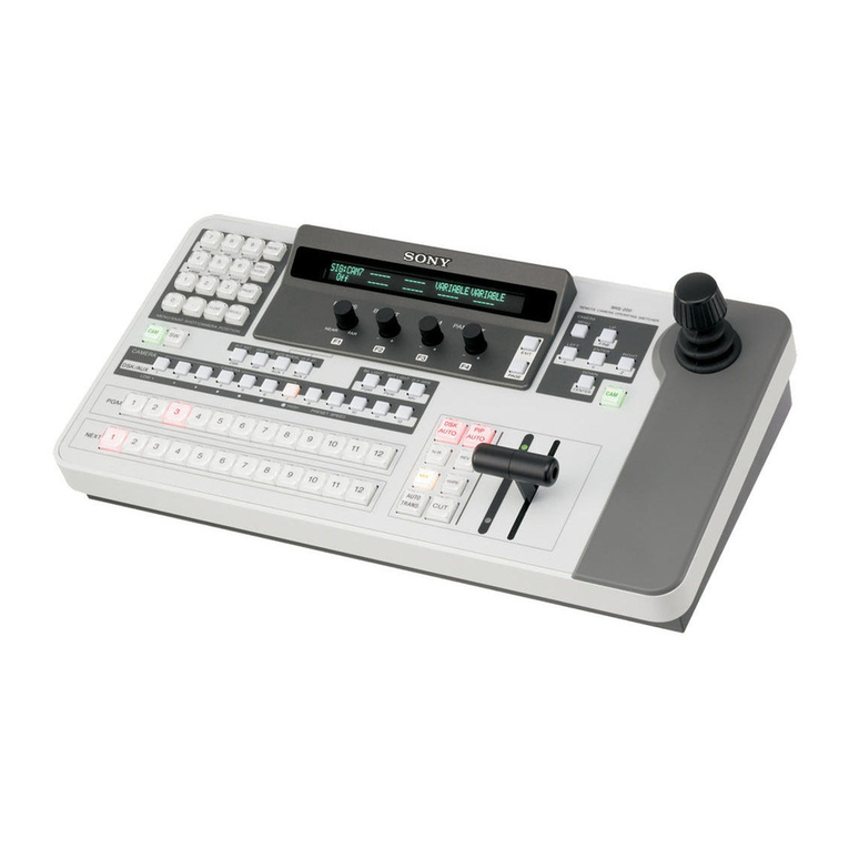
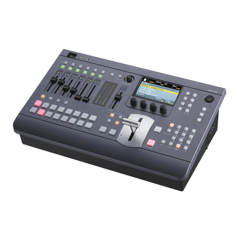
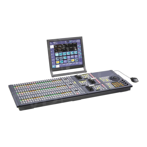
Sony DFS-900M User manual

4192719140
Multi Format
Switcher
Operating Instructions
Software Version 2.0
Before operating the unit, please read this manual thoroughly
and retain it for future reference.
DFS-900M
4-192-719-14 (2)
© 2010 Sony Corporation
Printed in Japan

2
Owner’s Record
The model and serial numbers are located on the bottom.
Record these numbers in the spaces provided below.
Refer to these numbers whenever you call upon your Sony
dealer regarding this product.
Model No. Serial No.
To reduce the risk of fire or electric shock,
do not expose this apparatus to rain or
moisture.
To avoid electrical shock, do not open the
cabinet. Refer servicing to qualified
personnel only.
THIS APPARATUS MUST BE EARTHED.
For the customers in the U.S.A.
This equipment has been tested and found to comply with
the limits for a Class A digital device, pursuant to Part 15
of the FCC Rules. These limits are designed to provide
reasonable protection against harmful interference when
the equipment is operated in a commercial environment.
This equipment generates, uses, and can radiate radio
frequency energy and, if not installed and used in
accordance with the instruction manual, may cause
harmful interference to radio communications. Operation
of this equipment in a residential area is likely to cause
harmful interference in which case the user will be
required to correct the interference at his own expense.
You are cautioned that any changes or modifications not
expressly approved in this manual could void your
authority to operate this equipment.
All interface cables used to connect peripherals must be
shielded in order to comply with the limits for a digital
device pursuant to Subpart B of Part 15 of FCC Rules.
This device complies with Part 15 of the FCC Rules.
Operation is subject to the following two conditions: (1)
this device may not cause harmful interference, and (2) this
device must accept any interference received, including
interference that may cause undesired operation.
For the customers in Canada
This Class A digital apparatus complies with Canadian
ICES-003.
This symbol is intended to alert the user to
the presence of important operating and
maintenance (servicing) instructions in the
literature accompanying the appliance.
WARNING: THIS WARNING IS APPLICABLE FOR
USA ONLY.
If used in USA, use the UL LISTED power cord specified
below.
DO NOT USE ANY OTHER POWER CORD.
Plug Cap Parallel blade with ground pin
(NEMA 5-15P Configuration)
Cord Type SJT, three 16 or 18 AWG wires
Length Minimum 1.5m (4 ft .11in.),
Less than 2.5 m (8 ft .3 in.)
Rating Minimum 10A, 125V
Using this unit at a voltage other than 120V may require
the use of a different line cord or attachment plug, or both.
To reduce the risk of fire or electric shock, refer servicing
to qualified service personnel.
WARNING: THIS WARNING IS APPLICABLE FOR
OTHER COUNTRIES.
1. Use the approved Power Cord (3-core mains lead) /
Appliance Connector / Plug with earthing-contacts that
conforms to the safety regulations of each country if
applicable.
2. Use the Power Cord (3-core mains lead) / Appliance
Connector / Plug conforming to the proper ratings
(Voltage, Ampere).
If you have questions on the use of the above Power Cord
/ Appliance Connector / Plug, please consult a qualified
service personnel.
IMPORTANT (for BKDF-901/902)
The nameplate is located on the bottom.
For the customers in Europe
This product with the CE marking complies with the EMC
Directive issued by the Commission of the European
Community.
Compliance with this directive implies conformity to the
following European standards:
• EN55103-1 : Electromagnetic Interference(Emission)
• EN55103-2 : Electromagnetic Susceptibility(Immunity)
This product is intended for use in the following
Electromagnetic Environment: E4 (controlled EMC
environment, ex. TV studio).
The manufacturer of this product is Sony Corporation, 1-
7-1 Konan, Minato-ku, Tokyo, Japan.
WARNING

3
The Authorized Representative for EMC and product
safety is Sony Deutschland GmbH, Hedelfinger Strasse
61, 70327 Stuttgart, Germany. For any service or
guarantee matters please refer to the addresses given in
separate service or guarantee documents.
This apparatus shall not be used in the residential area.
For the customers in Europe, Australia and New
Zealand
WARNING
This is a Class A product. In a domestic environment, this
product may cause radio interference in which case the
user may be required to take adequate measures.
For kundene i Norge
Dette utstyret kan kobles til et IT-strømfordelingssystem.
For DFS-900M
Attention-when the product is installed in Rack:
1. Prevention against overloading of branch circuit
When this product is installed in a rack and is supplied
power from an outlet on the rack, please make sure that
the rack does not overload the supply circuit.
2. Providing protective earth
When this product is installed in a rack and is supplied
power from an outlet on the rack, please confirm that the
outlet is provided with a suitable protective earth
connection.
3. Internal air ambient temperature of the rack
When this product is installed in a rack, please make
sure that the internal air ambient temperature of the rack
is within the specified limit of this product.
4. Prevention against achieving hazardous condition due
to uneven mechanical loading
When this product is installed in a rack, please make
sure that the rack does not achieve hazardous condition
due to uneven mechanical loading.
5. Install the equipment while taking the operating
temperature of the equipment into consideration
For the operating temperature of the equipment, refer to
the specifications of the Operation Manual.
6. When performing the installation, keep the following
space away from walls in order to obtain proper exhaust
and radiation of heat.
Right, Left : 10 cm (4 inches) or more
Rear : 10 cm (4 inched) or more
For BKDF-901/902
When installing the installation space must be secured in
consideration of the ventilation and service operation.
• Do not block the ventilation slots at the left side and right
side panels, and vents of the fans.
• Leave a space around the unit for ventilation.
• Leave more than 10 cm of space in the rear of the unit to
secure the operation area.
When the unit is installed on the desk or the like, leave at
least 10 cm of space in the left and right sides. Leaving 10
cm or more of space above the unit is recommended for
service operation.
For the customers in Taiwan only
For the State of California, USA only
Perchlorate Material - special handling may apply, See
www.dtsc.ca.gov/hazardouswaste/perchlorate
Perchlorate Material : Lithium battery contains
perchlorate.
Afin de réduire les risques d’incendie ou
d’électrocution, ne pas exposer cet
appareil à la pluie ou à l’humidité.
Afin d’écarter tout risque d’électrocution,
garder le coffret fermé. Ne confier
l’entretien de l’appareil qu’à un personnel
qualifié.
CET APPAREIL DOIT ÊTRE RELIÉ À LA
TERRE.
AVERTISSEMENT
1. Utilisez un cordon d’alimentation (câble secteur à 3
fils)/fiche femelle/fiche mâle avec des contacts de mise
à la terre conformes à la réglementation de sécurité
locale applicable.
2. Utilisez un cordon d’alimentation (câble secteur à 3
fils)/fiche femelle/fiche mâle avec des caractéristiques
nominales (tension, ampérage) appropriées.
Pour toute question sur l’utilisation du cordon
d’alimentation/fiche femelle/fiche mâle ci-dessus,
consultez un technicien du service après-vente qualifié.
IMPORTANT (pour BKDF-901/902)
La plaque signalétique se situe sous l’appareil.
Pour les clients au Canada
Cet appareil numérique de la classe A est conforme à la
norme NMB-003 du Canada.
Pour les clients en Europe
Ce produit portant la marque CE est conforme à la
Directive sur la compatibilité électromagnétique (EMC)
émise par la Commission de la Communauté européenne.
AVERTISSEMENT

4
La conformité à cette directive implique la conformité aux
normes européennes suivantes:
• EN55103-1: Interférences électromagnétiques
(émission)
• EN55103-2: Sensibilité électromagnétique (immunité)
Ce produit est prévu pour être utilisé dans l’environnement
électromagnétique suivant: E4 (environnement EMC
contrôlé, ex. studio de télévision).
Le fabricant de ce produit est Sony Corporation, 1-7-1
Konan, Minato-ku, Tokyo, Japon.
Le représentant autorisé pour EMC et la sécurité des
produits est Sony Deutschland GmbH, Hedelfinger Strasse
61, 70327 Stuttgart, Allemagne. Pour toute question
concernant le service ou la garantie, veuillez consulter les
adresses indiquées dans les documents de service ou de
garantie séparés.
Ne pas utiliser cet appareil dans une zone résidentielle.
Pour les clients en Europe, Australie et Nouvelle-
Zélande
AVERTISSEMENT
Il s’agit d’un produit de Classe A. Dans un environnement
domestique, cet appareil peut provoquer des interférences
radio, dans ce cas l’utilisateur peut être amené à prendre
des mesures appropriées.
Um die Gefahr von Bränden oder
elektrischen Schlägen zu verringern, darf
dieses Gerät nicht Regen oder
Feuchtigkeit ausgesetzt werden.
Um einen elektrischen Schlag zu
vermeiden, darf das Gehäuse nicht
geöffnet werden. Überlassen Sie
Wartungsarbeiten stets nur qualifiziertem
Fachpersonal.
DIESES GERÄT MUSS GEERDET
WERDEN.
WARNUNG
1. Verwenden Sie ein geprüftes Netzkabel (3-adriges
Stromkabel)/einen geprüften Geräteanschluss/einen
geprüften Stecker mit Schutzkontakten entsprechend
den Sicherheitsvorschriften, die im betreffenden Land
gelten.
2. Verwenden Sie ein Netzkabel (3-adriges Stromkabel)/
einen Geräteanschluss/einen Stecker mit den
geeigneten Anschlusswerten (Volt, Ampere).
Wenn Sie Fragen zur Verwendung von Netzkabel/
Geräteanschluss/Stecker haben, wenden Sie sich bitte an
qualifiziertes Kundendienstpersonal.
WICHTIG (für BKDF-901/902)
Das Namensschild befindet sich auf der Unterseite des
Gerätes.
Für Kunden in Europa
Dieses Produkt besitzt die CE-Kennzeichnung und erfüllt
die EMV-Richtlinie der EG-Kommission.
Angewandte Normen:
• EN55103-1: Elektromagnetische Verträglichkeit
(Störaussendung)
• EN55103-2: Elektromagnetische Verträglichkeit
(Störfestigkeit)
Für die folgende elektromagnetische Umgebung: E4
(kontrollierter EMV-Bereich, z.B. Fernsehstudio).
Der Hersteller dieses Produkts ist Sony Corporation, 1-7-1
Konan, Minato-ku, Tokyo, Japan.
Der autorisierte Repräsentant für EMV und
Produktsicherheit ist Sony Deutschland GmbH,
Hedelfinger Strasse 61, 70327 Stuttgart, Deutschland. Bei
jeglichen Angelegenheiten in Bezug auf Kundendienst
oder Garantie wenden Sie sich bitte an die in den separaten
Kundendienst- oder Garantiedokumenten aufgeführten
Anschriften.
Dieser Apparat darf nicht im Wohnbereich verwendet
werden.
Für Kunden in Europa, Australien und
Neuseeland
WARNUNG
Dies ist eine Einrichtung, welche die Funk-Entstörung
nach Klasse A besitzt. Diese Einrichtung kann im
Wohnbereich Funkstörungen verursachen; in diesem Fall
kann vom Betreiber verlangt werden, angemessene
Maßnahmen durchzuführen und dafür aufzukommen.
WARNUNG

Table of Contents 5
Table of Contents
Chapter 1 Overview
Features of This System ...............................................................10
Functions Newly Supported in Version 2.0 ........................................ 11
Chapter 2 Names and Functions of Parts
BKDF-901 1M/E Control Panel......................................................12
BKDF-901 Operating Blocks.............................................................. 12
1External Connections and Power Block ........................................ 13
2KEYER Block ............................................................................... 13
3KEY DELEGATION Block.......................................................... 14
4Cross-Point Bus Block .................................................................. 14
5Transition Block ............................................................................ 14
6Joystick Block ............................................................................... 15
7Numeric Keypad............................................................................ 16
8DME/SETUP Block ...................................................................... 17
9Display Panel/Menu Control Block............................................... 18
BKDF-901 Rear Panel......................................................................... 18
BKDF-902 1.5M/E Control Panel...................................................20
BKDF-902 Operating Blocks.............................................................. 20
1External Connections and Power Block ........................................ 21
2KEYER Block ............................................................................... 21
3Key/AUX (Auxiliary) Bus Control Block..................................... 21
4M/E Cross-Point Bus Block .......................................................... 22
5PROGRAM/PRESET Cross-Point Bus Block .............................. 22
6PROGRAM/PRESET Transition Block........................................ 23
7DSK (Downstream Key)/Fade to Black Control Block ................ 23
8M/E Transition Block .................................................................... 24
9DME/SETUP Block ...................................................................... 24
0Joystick Block ............................................................................... 25
qa Numeric Keypad............................................................................ 25
qs Display Panel/Menu Control Block............................................... 25
BKDF-902 Rear Panel......................................................................... 25
DFS-900M Processor Unit.............................................................27
Front Panel .......................................................................................... 27
Rear Panel............................................................................................ 27

6Table of Contents
Options ...........................................................................................30
BKDF-910 4 SDI Input Board ............................................................ 30
BKDF-911 2 SD Video Input Board................................................... 30
BKDF-912 2 DVI Input Board............................................................ 30
BKDF-960 4 SDI Output Board.......................................................... 30
BKDF-961 2 SD Video Output Board ................................................ 30
BKDF-962 2 DVI Output Board ......................................................... 31
BKDF-990 Power Supply Unit ........................................................... 31
Other Options ...................................................................................... 31
Chapter 3 Preparations
Connecting Peripheral Devices....................................................32
Connection Example 1: Live Recording / Playout System ................. 32
Connection Example 2: System with Editor Connected ..................... 34
Connection Example 3: Connection to a Device Equipped with a DVI
(DVI-I) Connector ..................................................................... 36
Installing Optional Expansion Boards.........................................38
Installing I/O Expansion Boards ......................................................... 38
Installing Function Expansion Boards ................................................ 45
Installing the BKDF-990 Power Supply Unit ..................................... 50
Connecting Up the Switcher.........................................................53
Changing the Internal Switch Setting in the Processor Unit (When Using
the BKDF-902) .......................................................................... 53
Connecting the Processor Unit and the Control Panel ........................ 56
Powering the System On ..................................................................... 57
Menu Operations ...........................................................................62
Basic Menu Configuration .................................................................. 62
Displaying Menus................................................................................ 62
Operating in Menus ............................................................................. 63
Menu Operations in the GUI Menus ................................................... 63
Basic Switcher Settings................................................................70
Setting the Video Format .................................................................... 70
Making Input and Output Reference Sync Signal Settings................. 72
Making Settings Related to Input Signals ........................................... 73
Making Settings Related to Output Signals ........................................ 88
Making Other Settings....................................................................... 103

Table of Contents 7
Chapter 4 Basic Operations
Selecting Backgrounds...............................................................107
Switching Backgrounds..............................................................108
Cutting to a New Background ........................................................... 108
Cutting by using GPI output.............................................................. 110
Using Transitions to Switch to the Next Video (Mix and Wipe)...... 110
Switching with Mix Transitions........................................................ 112
Switching with Wipe and DME Wipe Transitions............................ 114
Setting Transition Rates .................................................................... 116
Using Color Mattes ......................................................................116
Assigning Color Mattes to Cross-Point Selection Buttons ............... 116
Changing the Colors of Color Mattes................................................ 116
Using Color Mattes in Background Transitions................................ 117
Using Internally Stored Still Images ..........................................117
Acquiring Still Image Files ............................................................... 117
Using Stored Still Images in Background Transitions ...................... 119
Using 32-bit TGA Still Image Files in Keys..................................... 119
Writing Still Images to USB Flash Drives ........................................ 120
Deleting Still Image Files.................................................................. 120
Using Keys to Compose Video...................................................121
Setting Up Keys................................................................................. 121
Inserting Keys by a Cut Transition.................................................... 125
Inserting Keys by a Mix Transition................................................... 126
Inserting Keys by a Wipe or DME Wipe Transition......................... 126
Changing Key Priorities .................................................................... 127
Applying DME Effects to Keys ........................................................ 128
Inserting Downstream Keys (with a Cut).......................................... 128
Inserting Downstream Keys (with a Mix)......................................... 129
Using Fade to Black ....................................................................130
Chapter 5 Adjusting Wipes and Keys
Customizing Wipe Patterns ........................................................131
Adding Borders to Wipe Patterns...................................................... 131
Modifying Wipe Patterns .................................................................. 132
Registering User Patterns .................................................................. 132
Customizing DME Effects ...........................................................133
Changing the Position, Shape, and Size of Images ........................... 133
Adding Borders to Images................................................................. 136
Adding Trail Effects, and Changing the Color Type ........................ 138
Adjusting 3D DME Warp Effects ..................................................... 139

8Table of Contents
Adding Lighting Effects.................................................................... 145
Registering User Patterns .................................................................. 146
Applying Masks to Keys .............................................................146
Adding Edges to Keys.................................................................147
Masking Downstream Keys with Box Masks ............................149
Chapter 6 Registering Operations and Settings
Event Operations .........................................................................150
Registering Events............................................................................. 150
Recalling Events................................................................................ 151
Deleting Events ................................................................................. 154
Sequence Operations..................................................................155
Creating Sequences ........................................................................... 155
Recalling Sequences.......................................................................... 155
Playing Sequences............................................................................. 157
Editing Sequences ............................................................................. 158
Deleting Sequences ........................................................................... 159
Chapter 7 External Control Interface Settings
Serial Interface Settings..............................................................160
Communications Protocol Settings ................................................... 161
Baud Rate Settings ............................................................................ 161
Parity Bit Settings.............................................................................. 161
GPI Input Settings........................................................................162
Tally Output Settings...................................................................163
GPI Output Settings.....................................................................165
Chapter 8 Other Operations and Settings
Backing Up Data ..........................................................................166
Backing Up, Restoring, and Clearing All Data ................................. 167
Backing Up, Restoring, and Clearing System Data .......................... 167
Backing Up, Restoring, and Clearing File Data................................ 167
Updating the System...................................................................168
Status Information .......................................................................169
To display the Status sub menus ....................................................... 169
Option Board Information ................................................................. 170

Table of Contents 9
Software Version Information........................................................... 170
Alarms ............................................................................................... 170
Chapter 9 3D Mode
Overview.......................................................................................171
I/O of 3D Mode Signals................................................................171
3D Mode Signal Assignments ....................................................172
System Settings...........................................................................173
Switching to 3D Mode ...................................................................... 173
Selecting the 2D/3D Mode of Stored Still Images............................ 173
3D Mode Operations....................................................................174
Appendix
Menu Structure ............................................................................175
Transition Menu (for Transition, Wipe, and DME Settings) ............ 175
Keyer Menu (for Key Settings) ......................................................... 176
Still Store Menu (for Still Image Settings)........................................ 178
Sequence Event Menu (for Sequence and Event Registration)......... 178
Setup Menu (for System Settings)..................................................... 179
DME Menu (for DME Settings)........................................................ 182
Pattern List ...................................................................................188
Wipe .................................................................................................. 188
Mask .................................................................................................. 190
DME Wipe ........................................................................................ 191
Messages and Actions to Take ..................................................196
Specifications ..............................................................................201
DFS-900M Processor Unit ................................................................ 201
BKDF-901 1M/E Control Panel........................................................ 201
BKDF-902 1.5M/E Control Panel..................................................... 202
Optional Products .............................................................................. 202
Pin Assignments ................................................................................ 205
Example Connection of GPI Input .................................................... 208
Example Connection of Tally/GPI Output........................................ 208
External Dimensions ...................................................................209
Glossary .......................................................................................212
Index .............................................................................................213

10 Features of This System
Chapter 1 Overview
Chapter1
Overview
Features of This System
The DFS-900M Multi Format Video Switcher is a compact switcher
incorporating Digital Multi Effects (DME) functionality, and supporting both
SD and HD systems.
Multi-format support
The system supports 480i/59.94 and 576i/50 formats for an SD system, and
1080i/59.94, 1080i/50, 720p/59.94, and 720p/50 formats for an HD system.
You can change the format selection with a simple menu operation.
Extensible inputs and outputs
Along with the standard equipment of SDI inputs and outputs (8 inputs, 4
outputs), the following inputs and outputs are available when optional
expansion boards are installed.
• SDI inputs and outputs (four channels): BKDF-910/BKDF-960 (of the four
channels, two channels provided with format converter)
• SD analog inputs and outputs (two channels): BKDF-911/BKDF-961
• DVI inputs and outputs (two channels): BKDF-912/BKDF-962
For details, see “Installing Optional Expansion Boards” (page 38)
Advanced special effects
As standard features, the system provides two DME channels and six keyers:
four full-function keyers and two simple downstream keyers (DSKs). A further
maximum of six optional DME channels enables warp and other visual effects.
Multi-view function
The optional multi-view function allows the system to display multiple video
images on a single monitor, by splitting the screen into 4, 10, or 16 images.
Using the maximum of two multi-view channels, all input video (24 channels)
and program/preview output can be viewed simultaneously on just two
monitors.
Simple operations in GUI menu screens
You can connect a PC monitor and USB mouse to make system settings in GUI
menus.

11
Features of This System
Chapter 1 Overview
You can also connect a commercially available touch panel monitor. This
allows you to select menu items simply by touching the panel, making it much
more convenient to change system settings and adjust setting values.
Compact and easy-to-use control panels
Two types of highly compact and easy-to-use control panels are available, each
one designed to meet the requirements of space-limited applications. Together
with the 3RU processor chassis, they are ideal for use in any situation where
space is at a premium.
The BKDF-902 1.5 M/E Control Panel has a built-in redundant power supply as
a standard feature, and allows you to select AUX outputs with key operations.
Functions Newly Supported in Version 2.0
Functions See
Input and output of SD
analog signals
BKDF-911 board (for input)
BKDF-961 board (for output)
Chapters 2 and 3
DVI input and output BKDF-912 board (for input)
BKDF-962 board (for output)
Chapters 2 and 3
3D mode Chapter 9
Turning ancillary data output on or off Chapter 3
GPI output setting Chapter 7

12 BKDF-901 1M/E Control Panel
Chapter 2 Names and Functions of Parts
Chapter2
Names and Functions of
Parts
BKDF-901 1M/E Control Panel
BKDF-901 Operating Blocks
This section explains the functions of control panel parts
by dividing them into nine blocks, as shown below.
For details, see the pages indicated within parentheses.
For information about the rear panel of the control panel,
see “BKDF-901 Rear Panel” (page 18).
1External Connections and Power
Block (page 13)
9Display Panel/Menu Control Block
(page 18)
8DME/SETUP Block (page 17)
7Numeric Keypad (page 16)
6Joystick Block (page 15)
2KEYER Block (page 13)
3KEY DELEGATION Block (page 14)
4Cross-Point Bus Block (page 14) 5Transition Block (page 14)

13
BKDF-901 1M/E Control Panel
Chapter 2 Names and Functions of Parts
1External Connections and Power
Block
This block provides a connector for USB flash drives,
buttons to turn control by editors and GPI on and off, and
a button to start the shutdown process.
aUSB MEMORY connector (Type-A)
Use to connect a USB flash drive.
The USB flash drive must be formatted with the FAT16 or
FAT32 file system.
bEDITOR button
Turns editor control on and off. When this button is on,
you can control the switcher from an editor. When you turn
this button on by pressing it twice in quick succession, the
Serial menu for setup operations appears in the display
panel.
cGPI button
Turns GPI control on and off. When this button is on, you
can perform GPI control of the switcher. When you turn
this button on by pressing it twice in quick succession, the
GPIO Tally menu appears in the display panel.
dSHUTDOWN (start shutdown process) button
When you press this button, lighting it, the message
“Shutdown? F2:OK F3:CANCEL” appears. Press the F2
knob to start data backup. When data backup finishes, you
can power the switcher off by using the POWER switch on
the rear panel of the control panel.
2KEYER Block
This block allows you to select a key type, to add a mask
or edge (shadow) to a key, and to enable or disable DME.
The operation target key must be selected in advance (see
page 14).
aKey type selection buttons
Press one of the following buttons, lighting it, to select a
key type.
EXT (external key) button: Press to create a key by using
separate signals for the key fill and key source.
SELF (self key) button: Press to create a key by using the
same signal for the key fill and key source.
CK (chroma key) button: Press to create a chroma key.
bMASK button
Press this button, turning it on, to apply a mask to a key.
When one of KEY1 to KEY4 is selected as the operation
target, the Key Mask sub menu appears when you press
this button. This menu allows you to select the mask
pattern and to specify the center position and size of the
mask.
When DSK1 or DSK2 is selected as the operation target,
the Box Mask sub menu appears when you press this
button. This menu allows you to specify a box mask
position.
cEDGE SHADOW button
Press this button, turning it on, to add an edge or shadow
to the key. When you press this button with one of KEY1
to KEY4 selected, the Edge Type sub menu appears,
allowing you to select the edge or shadow type, and to
specify the width and the color.
dDME ENABLE (enable/disable digital multi
effects) button
Enables or disables DME for each of the BKGD
(background) and KEY1 to KEY4 layers. This button
functions as a three-step switch. With each press, the DME
enable/disable state changes as follows, starting with the
button not lit (DME disabled).
First press: DME is enabled. As the key, use a white
signal for the entire screen.
r
Note
1USB MEMORY connector
2EDITOR button
3GPI button
4SHUTDOWN
button
1Key type selection buttons
2MASK button
3EDGE
SHADOW
button
4DME ENABLE button

14 BKDF-901 1M/E Control Panel
Chapter 2 Names and Functions of Parts
Second press: With DME still enabled, use a
key-processed signal as the key.
r
Third press: The button goes out, and DME is disabled
again.
3KEY DELEGATION Block
This block allows you to select KEY1 to KEY4, DSK1, or
DSK2 as the target of key, mask, and other operations.
When you press one of the buttons in this block, it selects
the corresponding key as the operation target.
The pressed button lights in green and all of the other
buttons go out.
If you press a button while it is lit in green, all of the
buttons go out and key is not selected as the operation
target.
The selection made here specifies the target of operations
with buttons in the following blocks.
• KEYER block
• DME settings buttons and USER button in the DME/
SETUP block.
• AUTO CK, WIPE POS, DME POS, and DME ROT
buttons in the joystick block.
Selections made with these buttons are linked to menu
operations. Operations with the buttons may cause a menu
to appear, and operations in the menu may cause the
buttons to light or go out.
4Cross-Point Bus Block
This block allows you to select material signals to use in
creating the video.
aPROGRAM selection button row
These buttons select current on-air background video.
For the functions of the various buttons, see “Assigning
video input signals to cross-point selection buttons” (page
75).
bPRESET selection button row
These buttons select the video that will be the on-air
background after a transition.
The signals that are assigned to the buttons in this row are
the same as the signals that are assigned to the buttons in
the PROGRAM selection button row.
About the SHIFT buttons
The SHIFT buttons on the right side of the PROGRAM
and PRESET selection button rows allow you to switch
between the two signals assigned to each button in the
rows.
The SHIFT buttons have two operating modes: one in
which the buttons function as shift buttons only while held
down, and one in which the shift function is alternately
enabled and disabled each time the buttons are pressed.
For details, see “Selecting the operating mode of the
SHIFT buttons” (page 104).
5Transition Block
This block allows you to set up and execute transitions.
aTRANS PVW (transition preview) button
Allows you to check the video of a transition before
carrying out the transition.
1PROGRAM selection button row
2PRESET selection button row
6FTB button
1TRANS PVW button
8Key priorities block
7Transition range and direction
buttons
4Transition execution block
3Transition type selection buttons
2Next transition selection buttons
5DSK transition buttons

15
BKDF-901 1M/E Control Panel
Chapter 2 Names and Functions of Parts
When you press this button, lighting it, and then execute a
transition with the fader lever, the video of the transition is
output to the preview screen.
• A transition preview is not output when you execute the
transition by using an AUTO TRANS button.
• A transition preview is not output when you execute a
DME wipe.
bNext transition selection buttons
Select the layer (BKGD, KEY1 to KEY4) to be used in a
transition. You can select multiple layers. Pressed buttons
light in orange. When a key is turned on, the Key On
indicators (red) above the KEY1 to KEY4 buttons light.
When DME effects are set for a layer, the DME indicator
(green) above that layer lights.
cTransition type selection buttons
MIX button: Press this button, lighting it, to select a mix
transition. The Rate menu appears in the display panel,
allowing you to specify the transition rate.
WIPE (FAM (full additive mix)) button: Press this
button, lighting it, to select a wipe transition. The
Wipe Pattern menu appears in the display panel,
allowing you to select the wipe pattern.
To select FAM, press this button while pressing the
MIX button. Both buttons light.
DME (NAM (non-additive mix)) button: Press this
button, lighting it, to use DME in a transition. The
DME Pattern menu appears in the display panel,
allowing you to select a DME wipe pattern.
To select NAM, press this button while pressing the
MIX button. Both buttons light.
dTransition execution block
CUT button: Executes a cut transition. The current video
changes instantly to the next video.
AUTO TRANS (auto transition) button: Executes an
automatic transition. The video changes according to
the currently specified transition rate.
Fader lever: Allows you to control a transition manually.
The video changes according to the position of the
fader lever as you move it up and down. You can limit
the effective range of the fader lever, so that the
transition is ended before you move it all the way to
the top or bottom.
For information about how to limit the range, see
“Limiting the effective range of the fader lever” (page
112).
eDSK (downstream key) transition buttons
DSK1 ON and DSK2 ON buttons: Instantly inserts or
deletes a downstream key. The button is turned on
when a downstream key is inserted.
AUTO TRANS (auto transition) button: Executes a
transition using a downstream key.
fFTB (fade to black) button
Executes a transition in which the video changes to black.
The transition rate is specified by a special fade-to-black
setting.
gTransition range and direction buttons
FADER LIMIT button: Limits the effective range of the
fader lever. The range limitation is enabled when this
button is pressed, lighting it. When you press the
button twice to turn it on, the Fader Limit menu
appears in the display panel. This menu allows you to
specify the effective range of the fader lever as a
percentage value. When you press the SHIFT button at
the right side of the DME/SETUP block, the effective
range is limited to the current fader lever position.
NOR/REV (normal/reverse) button: Press this button,
lighting it, to reverse the direction of the transition
each time a transition is executed.
REVERSE button: Press this button, lighting it, to
execute a transition in the reverse direction.
hKey priorities block
This block allows you to change the priorities of the four
keys.
For information about how to change the priorities, see
“Changing Key Priorities” (page 127).
6Joystick Block
This block allows you to make settings related to positions
on the screen.
Notes
1DEFAULT button
2AUTO CK button
3DME POS button
5DME ROT button
6WIPE POS button
4FINE button
7X, Y, Z buttons
8Joystick

16 BKDF-901 1M/E Control Panel
Chapter 2 Names and Functions of Parts
aDEFAULT button
Returns the setting values of parameters assigned to the
joystick to the default values.
bAUTO CK (auto chroma key) button
Initiates and confirms the creation of an auto chroma key.
Pressing this button once selects auto chroma key mode, in
which you can select the color you want to use as the key
color to cut out the foreground. Pressing it again confirms
the creation of the auto chroma key and returns to manual
adjustment mode (the CK Manual 1 menu appears in the
display panel).
This button is enabled only when one of KEY1 to KEY4 is
selected (see page 14).
For more information about how to create auto chroma
keys, see “To create an auto chroma key” (page 122).
cDME POS (DME image position) button
Displays the menu that allows you to specify the position
of a DME image. To specify the position of a DME image
with the joystick, press this button to display the menu and
then adjust the position with the joystick.
dFINE (fine adjustment) button
Selects fine adjustments to setting values when the joystick
is moved. Press this button, lighting it, when you want to
modify a setting value in small steps.
eDME ROT (DME rotation angle) button
Displays the menu that allows you to specify the rotation
angle of a DME image. You can adjust the angle with the
joystick.
fWIPE POS (wipe center position) button
Displays the menu that allows you to specify the center
position of a wipe pattern. To specify the center position
with the joystick, press this button to display the menu and
then adjust the position with the joystick.
This button is enabled only when key is not selected as the
operation target (see page 14).
gX, Y, Z (parameter selection) buttons
Select parameters to adjust with the joystick. You can
move the joystick to adjust the parameter selected by the
lit button.
hJoystick
As shown in the figure below, you can change X, Y, and Z
coordinate parameters by moving the joystick left, right,
up and down, or by rotating it to the left or right.
7Numeric Keypad
The numeric keypad allows you to enter parameter values
in menu operations.
When the current parameter has a settable value, you can
press the corresponding knob F1 to F4 to enable direct
input of a numeric value. Enter the value with the numeric
buttons (0 to 9) and then press the ENTER button to
confirm it. Press the CANCEL button to cancel the entry
operation.
The buttons in the numeric keypad can also be used to
switch between menu mode, event mode, and sequence
mode, and to perform other operations according to the
current mode.
Buttons used to enter numeric values and
symbols
Buttons used when the MENU button is lit (menu
mode)
Button display Function
0 to 9 Enter numeric values.
. Enters a decimal point (.).
– Enters a minus sign (–).
CANCEL Cancels numeric input.
ENTER Confirms numeric input.
Button display Function
jSwitches to the previous menu.
Z coordinate –
X coordinate –
Z coordinate +
X coordinate +
Y coordinate +
Y coordinate –

17
BKDF-901 1M/E Control Panel
Chapter 2 Names and Functions of Parts
Buttons used when the EVENT button is lit (event
mode)
Buttons used when the SEQ button is lit
(sequence mode)
8DME/SETUP Block
This block provides buttons for use in DME setting and
setup operations.
When the SHIFT button on the right side is not lit, the
buttons function as DME setting buttons (top-side
indications on the buttons). When the SHIFT button is lit,
the buttons function as setup buttons (bottom-side
indications on the buttons).
aDME setting buttons
BASIC (basic DME settings) button: Displays a menu
that allows you to make basic settings for DME
images, such as position and rotation angle.
BORDER button: Displays a menu that allows you to set
the color, width, softness and other attributes of
borders added to DME images.
SUB EFF (sub effect) button: Displays a menu that
allows you to add a Chroma Control sub effect to a
DME image.
WARP button: Displays a menu that allows you to set up
various warp patterns that can be applied by DME.
After the menu appears, each press of the WARP
button switches to the next pattern that can be set up.
LIGHT (light source) button: Displays a menu that
allows you to specify and adjust light source effects
added to 3D effects.
(Not supported in this version.)
bSetup buttons
AUX (auxiliary) button: Displays an AUX bus output
menu that allows you to select the source, format, and
level of output signals.
MATTE button: When pressed with the SHIFT button lit,
displays a menu that allows you to select the
luminance, saturation, and hue of internally generated
color matte signals.
INPUT button: When pressed with the SHIFT button lit,
displays a menu that allows you to make settings
related to input signals, for example make settings for
assigning input signals to a bus.
MV (multi-view) button: When pressed with the SHIFT
button lit, displays a menu that allows you to select the
number of child windows in the optional multi-view
display and to select the signals to assign to each child
window.
SYSTEM button: When pressed with the SHIFT button
lit, displays a menu that allows you to make system
settings, such as the video format, the system delay,
and the date and time.
STATUS button: When pressed with the SHIFT button
lit, displays a menu that allows you to check status
information such as the installed option boards, the
firmware version, and alarms.
JSwitches to the next menu.
EVENT Switches to event mode.
SEQ Switches to sequence mode.
hSwitches to the previous sub menu.
HSwitches to the next sub menu.
Button display Function
EVENT Exits event mode and switches to menu
mode.
STORE Stores an event.
RECALL Recalls an event.
INSERT Specifies settings to be recalled in event
mode.
Button display Function
SEQ Exits sequence mode and switches to
menu mode.
STORE Stores a sequence.
XPauses play of a sequence, or restarts
play.
LOOP Specifies loop play as the play mode of a
sequence.
DIR Reverses the direction of play.
RECALL Recalls a sequence.
Bx Starts play of a sequence, or stops play.
NEW Clears sequence memory.
DELETE Deletes a sequence or key frame.
INSERT Inserts a key frame.
h, HMoves the current key frame.
j, JSwitches the sequence menu.
Button display Function
1DME setting buttons
2Setup buttons
3USER/STILL button
4SHIFT button

18 BKDF-901 1M/E Control Panel
Chapter 2 Names and Functions of Parts
cUSER/STILL button
When pressed with the SHIFT button unlit, displays the
menu used for management of user specified wipe patterns
and DME wipe patterns. When pressed with the SHIFT
button lit, displays the menu for still image storage
operations, such as download, capture, and export.
dSHIFT button
Enables the functions of the STILL button and the setup
buttons (except for the AUX button).
9Display Panel/Menu Control
Block
aDisplay panel
Displays the operation and setting menus of the switcher.
The menu title appears in the upper left. Below it is the
display area for four parameters. Useful supporting
information for menu operations may appear in the upper
right.
bF1 to F4 knobs
The F1 to F4 adjustment knobs are located beneath the
parameter display area. They correspond to up to four
parameters per menu. You can set parameter values by
rotating the knobs or by pressing a knob and entering the
value for the corresponding parameter in the numeric
keypad.
Instead of specifying parameter values, some menu items
may select actions such as store or delete. To execute an
action, press the corresponding knob and hold it down for
one second or longer.
BKDF-901 Rear Panel
1Display panel
2F1 to F4 knobs
Menu title Supporting information
The F1 to F4 knobs correspond to menu parameters
1EXT DISPLAY connector
2PROCESSOR connector
3MAINTENANCE connector
4DEVICE connector
7POWER switch
6-AC IN connector
5Ground terminal

19
BKDF-901 1M/E Control Panel
Chapter 2 Names and Functions of Parts
aEXT DISPLAY (external display) connector
(high-density D-sub 15-pin)
You can also connect an optional touch panel monitor.
bPROCESSOR connector (RJ-45)
Use the supplied control cable to connect to the PANEL
connector of the processor unit.
This connector is for connection to the DFS-900M
processor unit only. It cannot be connected to the processor
unit of any other system.
• When you connect the PROCESSOR connector of the
unit to peripheral devices, use a shielded-type cable to
prevent malfunction due to radiation noise.
• For safety, do not connect the connector for peripheral
device wiring that might have excessive voltage to this
port. Follow the instructions for this port.
Par mesure de sécurité, ne raccordez pas le connecteur
pour le câblage de périphériques pouvant avoir une tension
excessive à ce port. Suivez les instructions pour ce port.
Aus Sicherheitsgründen nicht mit einem
Peripheriegerät-Anschluss verbinden, der zu starke
Spannung für diese Buchse haben könnte. Folgen Sie den
Anweisungen für diese Buchse.
cMAINTENANCE connector (D-sub 9-pin)
Provided for inspection / maintenance. Not used for
operating this system.
dDEVICE connector (USB Type-A)
Allows you to connect an optional touch panel monitor or
a mouse.
eGround terminal
Connect to the system ground wire.
f-AC IN connector
Connect to an AC power with an AC power cord (not
supplied).
gPOWER switch
Powers the control panel on and off.
Note
CAUTION
ATTENTION
VORSICHT

20 BKDF-902 1.5M/E Control Panel
Chapter 2 Names and Functions of Parts
BKDF-902 1.5M/E Control Panel
BKDF-902 Operating Blocks
This section explains the functions of control panel parts
by dividing them into twelve blocks, as shown below.
For details, see the pages indicated within parentheses.
For information about the rear panel of the control panel,
see “BKDF-902 Rear Panel” (page 25).
4M/E Cross-Point Bus Block (page 22)
3Key/AUX Bus Control Block (page 21)
2KEYER Block (page 13)
1External Connections and Power Block (page 13)
qsDisplay Panel/Menu Control Block (page 18)
qaNumeric Keypad (page 16)
0Joystick Block (page 15)
5PROGRAM/PRESET Cross-Point Bus Block (page 22)
6PROGRAM/PRESET Transition Block (page 23)
7DSK/Fade to Black Control Block (page 23)
8M/E Transition Block (page 24)
9DME/SETUP Block (page 24)
Other manuals for DFS-900M
1
Table of contents
Other Sony Switch manuals

Sony
Sony XA-C30 - 2 Output Selector User manual

Sony
Sony XVS Series User manual

Sony
Sony XVS-9000-C User manual

Sony
Sony MCS-8M User manual

Sony
Sony DVS-7200 User manual

Sony
Sony MVS-8000X System User manual

Sony
Sony DFS-700 User manual

Sony
Sony DMX-SW1 - Bravia Input Link User manual

Sony
Sony PVS-R102 User manual

Sony
Sony MVS-8000G-C Quick start guide

Sony
Sony BKDS-7017 User manual

Sony
Sony MVS-8000SF User manual

Sony
Sony G363-ZR0-LAX1 User manual

Sony
Sony DFS-700A User manual

Sony
Sony DVS-7150 User manual

Sony
Sony BRS-200 User manual

Sony
Sony MVS-3000A User guide

Sony
Sony XA-U40D User manual

Sony
Sony MVS-6000 User manual

Sony
Sony MVS-8000X SystemMVS-7000X System User manual