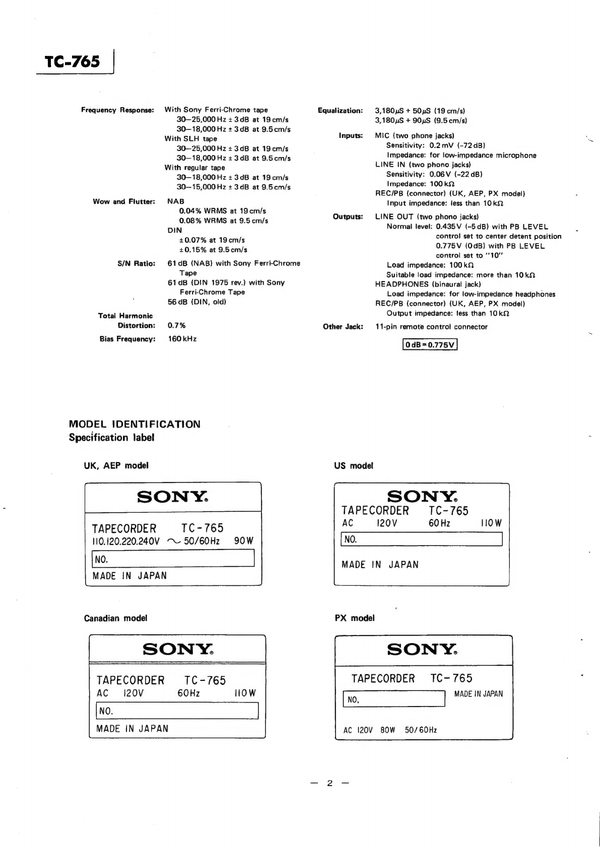
Sony TC-765 User manual
Other Sony Tape Deck manuals


Sony
Sony DTC-57ES User manual

Sony
Sony MDS-JA50ES / Mode d’emploi User manual

Sony
Sony TC-630 User manual

Sony
Sony TC-765 Setup guide

Sony
Sony PCM-R500 - Dat Recorder User manual

Sony
Sony DTC-A8 User manual

Sony
Sony DTC59ES User manual

Sony
Sony DTC-ZA5ES User manual

Sony
Sony DTC-1000 User manual

Sony
Sony DTC59ES User manual