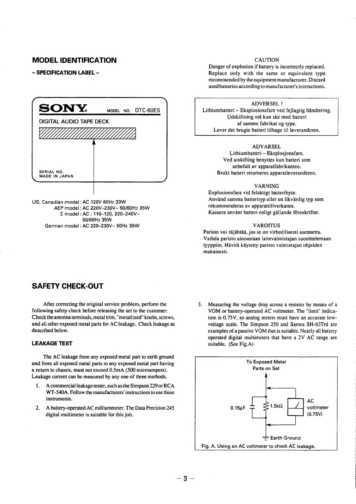
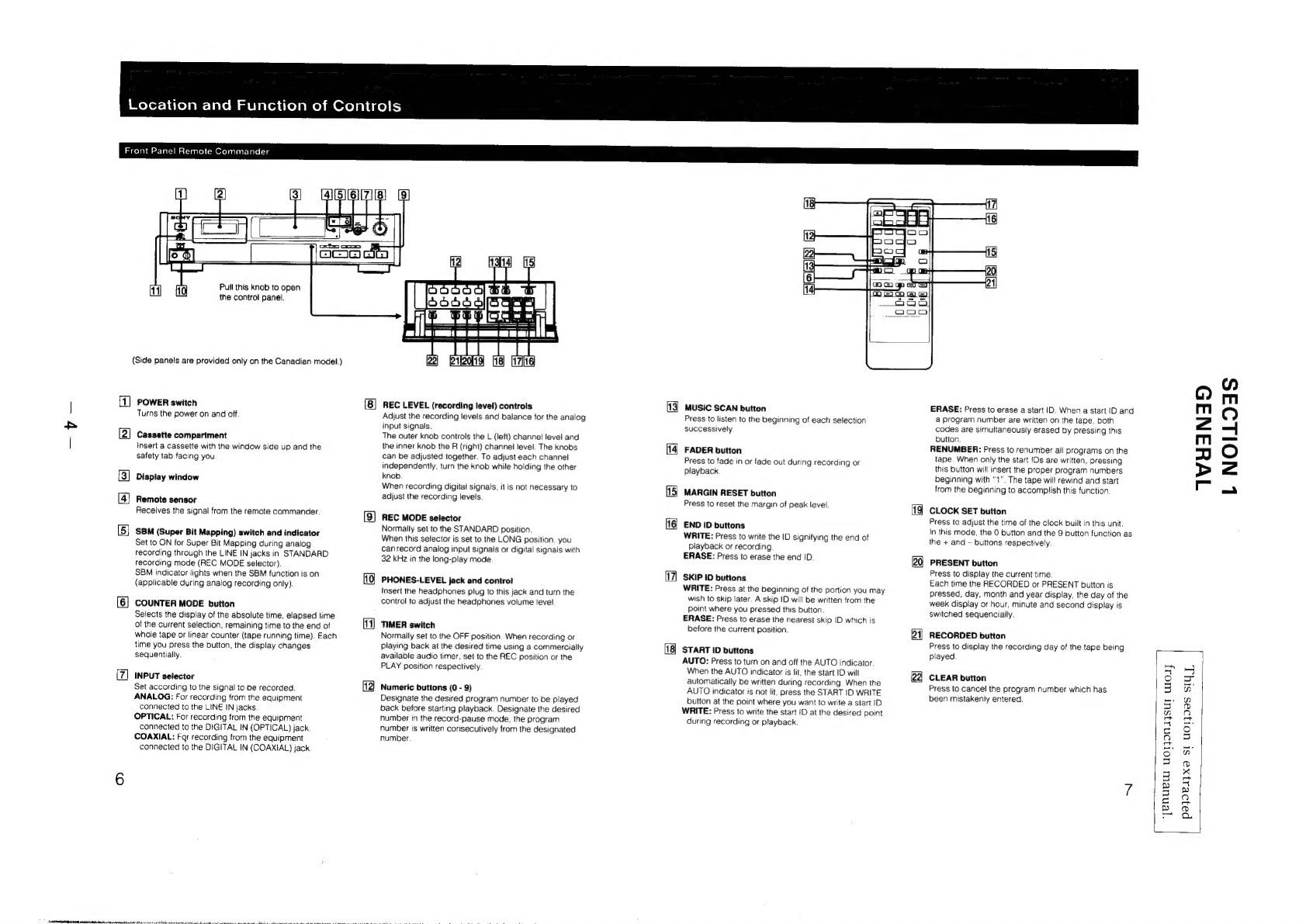
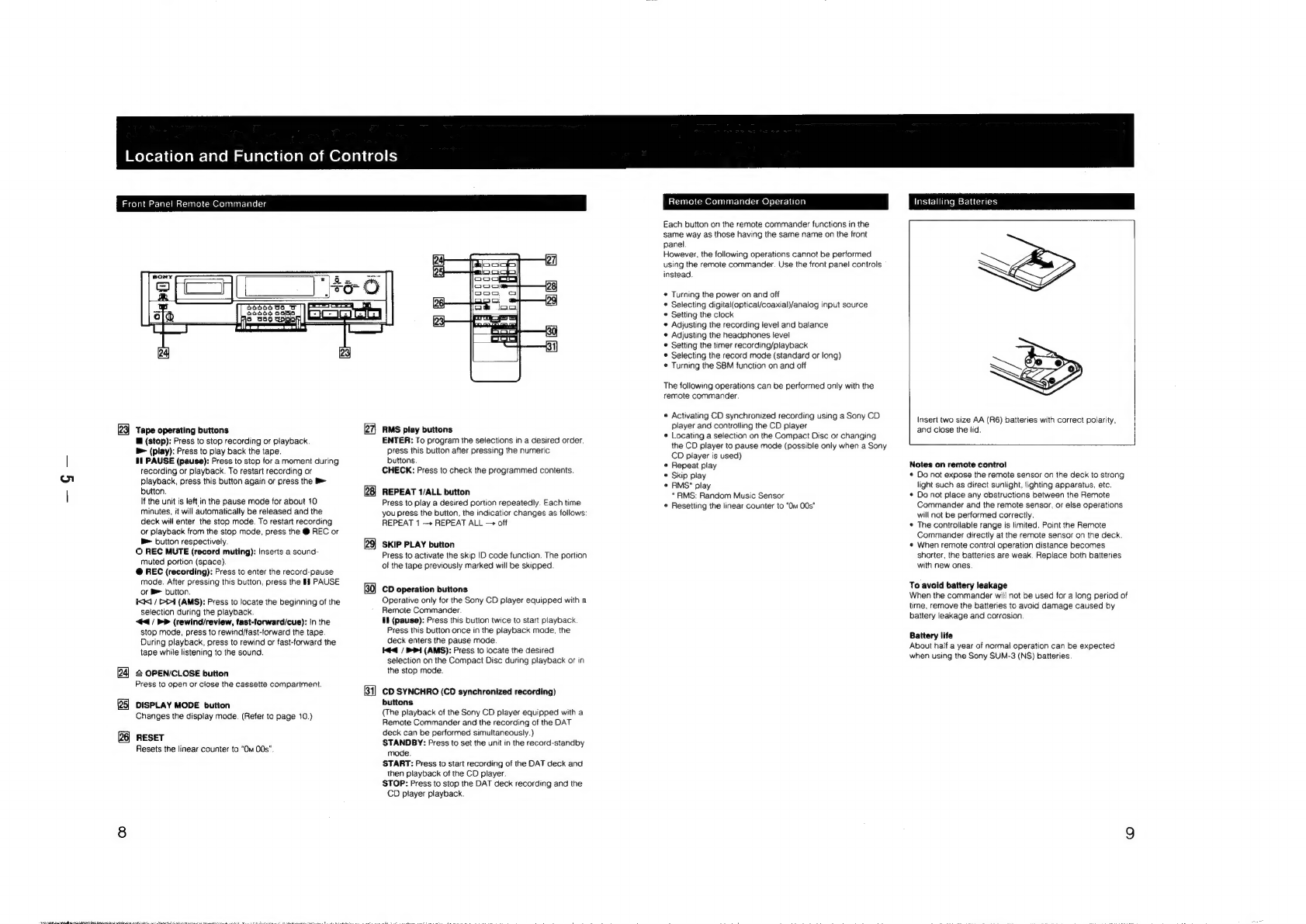
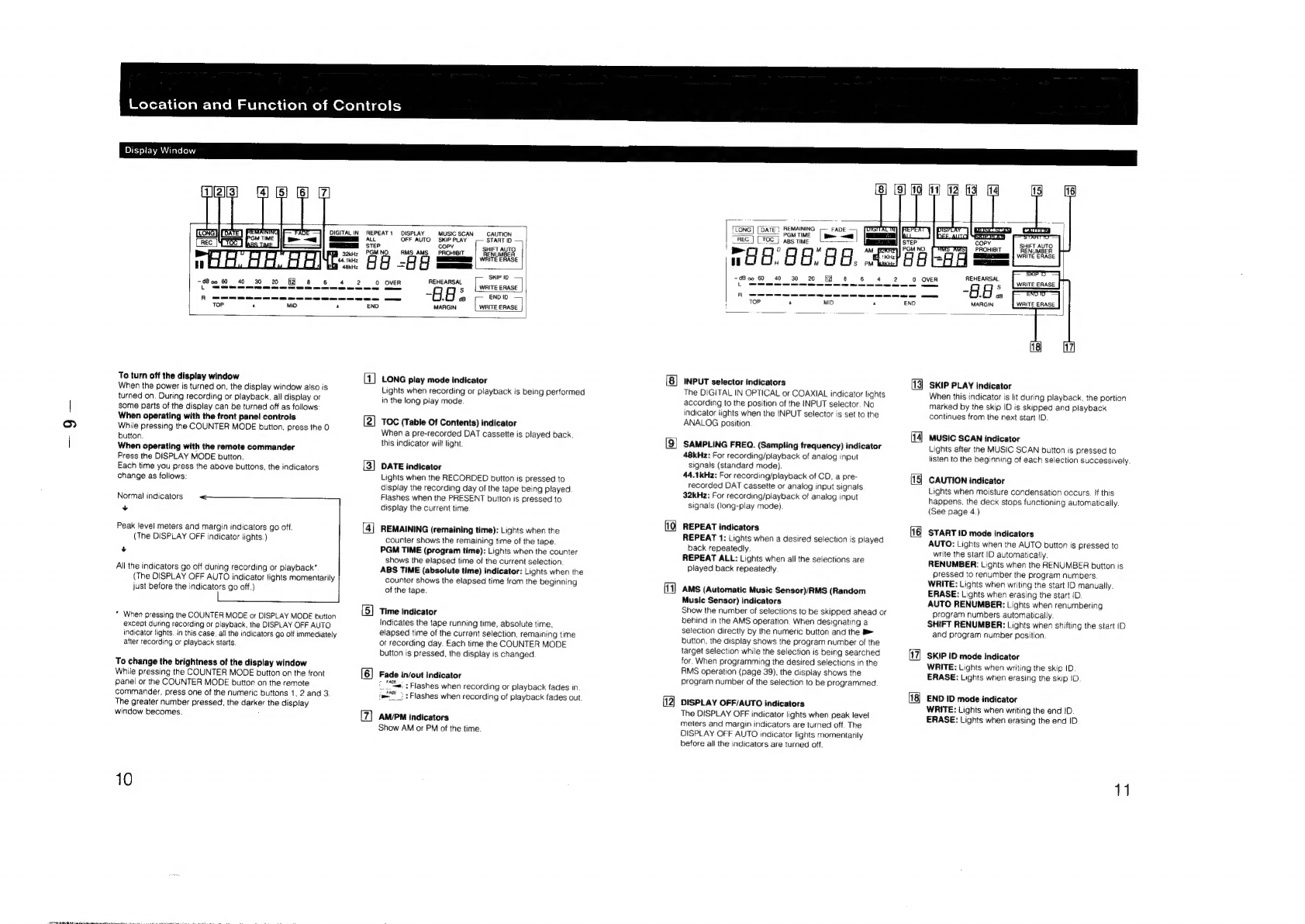
manuals.online logo
Brands
  1. Home
  2. •
  3. Brands
  4. •
  5. Sony
  6. •
  7. Tape Deck
  8. •
  9. Sony DTC-60ES User manual

Sony DTC-60ES User manual

Other manuals for DTC-60ES

1

Other Sony Tape Deck manuals

Sony TC-765 User manual

Sony

Sony TC-765 User manual

Sony DTC-670 User manual

Sony

Sony DTC-670 User manual

Sony DTC59ES User manual

Sony

Sony DTC59ES User manual

Sony TC-388-4 User manual

Sony

Sony TC-388-4 User manual

Sony TC-854-4 User manual

Sony

Sony TC-854-4 User manual

Sony PCM-R500 - Dat Recorder User manual

Sony

Sony PCM-R500 - Dat Recorder User manual

Sony PVW-2650 Service manual

Sony

Sony PVW-2650 Service manual

Sony GY-8240UWD User manual

Sony

Sony GY-8240UWD User manual

Sony DTC-ZA5ES User manual

Sony

Sony DTC-ZA5ES User manual

Sony DTC59ES User manual

Sony

Sony DTC59ES User manual

Sony PCM-R500 - Dat Recorder User manual

Sony

Sony PCM-R500 - Dat Recorder User manual

Sony PDW-F1600 User manual

Sony

Sony PDW-F1600 User manual

Sony DTC-77ES User manual

Sony

Sony DTC-77ES User manual

Sony DTC-57ES User manual

Sony

Sony DTC-57ES User manual

Sony TC-366 User manual

Sony

Sony TC-366 User manual

Sony TC-630 User manual

Sony

Sony TC-630 User manual

Sony DTC-ZA5ES User manual

Sony

Sony DTC-ZA5ES User manual

Sony DTC-670 User manual

Sony

Sony DTC-670 User manual

Sony DTC-A6 User manual

Sony

Sony DTC-A6 User manual

Sony DTC-A8 User manual

Sony

Sony DTC-A8 User manual

Sony TC-560D Setup guide

Sony

Sony TC-560D Setup guide

Sony PCM-R500 - Dat Recorder User manual

Sony

Sony PCM-R500 - Dat Recorder User manual

Sony DTC-A8 User manual

Sony

Sony DTC-A8 User manual

Sony DTC-790 User manual

Sony

Sony DTC-790 User manual

Popular Tape Deck manuals by other brands

Pioneer RT-1020L operating instructions

Pioneer

Pioneer RT-1020L operating instructions

3M 3M-Matic Dual S-867 II Instructions and parts list

3M

3M 3M-Matic Dual S-867 II Instructions and parts list

Pioneer GT-X5 Service manual

Pioneer

Pioneer GT-X5 Service manual

SilverStone 1232 manual

SilverStone

SilverStone 1232 manual

Teac X-2000 owner's manual

Teac

Teac X-2000 owner's manual

Hitachi D-980MU Service manual

Hitachi

Hitachi D-980MU Service manual

Teac A-6010GSL Service manual

Teac

Teac A-6010GSL Service manual

Hitachi D-900BS Service manual

Hitachi

Hitachi D-900BS Service manual

Kyocera D-611 Service manual

Kyocera

Kyocera D-611 Service manual

Kenwood KX-W595 instruction manual

Kenwood

Kenwood KX-W595 instruction manual

TANDBERG 11 instruction manual

TANDBERG

TANDBERG 11 instruction manual

Teac Tascam 3030 owner's manual

Teac

Teac Tascam 3030 owner's manual

Teac A-3300 Service manual

Teac

Teac A-3300 Service manual

Pioneer H-R99 KCU Service manual

Pioneer

Pioneer H-R99 KCU Service manual

Kenwood KX-W6070 instruction manual

Kenwood

Kenwood KX-W6070 instruction manual

Tascam BR-20 Series maintenance

Tascam

Tascam BR-20 Series maintenance

Kenwood KX-620 instruction manual

Kenwood

Kenwood KX-620 instruction manual

uher SG 560 Royal Servise manual

uher

uher SG 560 Royal Servise manual

manuals.online logo
manuals.online logoBrands
  • About & Mission
  • Contact us
  • Privacy Policy
  • Terms and Conditions

Copyright 2025 Manuals.Online. All Rights Reserved.

SERVICE
MANUAL
DIC-GOES
US
Model
Canadian
Model
AEP
Model
E
Model
Photo:
Black
type
SPECIFICATIONS
Digital
audio
tape
Rotary
head
Standard:
120
minutes.
Long-play
mode:
240
minutes
(with
DT-120)
Standard:
8.15
mm/s,
Long
play
mode:
4.075
mm/s
Standard:
2,000
rpm,
Long-play
mode:
1,000
rem
Double
Read
Solomon
code
Tape
Recording
head
Recording
time
Tape
speed
Drum
rotation
Error
correction
Tape
Track
pitch
Sampling
frequency
Modulation
system
Transfer
rate
2.46
Mbit/sec.
Number
of
channel
2
channels,
stereo
D/A
conversion
(Quantization)
Standard:
16-bit
linear
Long-play
mode:
12-bit
non-linear
Standard:
2
-
22,000
Hz
(+0.5
dB)
Long-play
mode:
2
-
(+0.5
dB)
Standard:
more
than
92
dB
Long-play
mode:
more
than
92
dB
Standard:
more
than
92
dB
Long-play
mode:
more
than
92
dB
Standard:
less
than
0.0045
%
(1
kHz)
Long-play
mode:
less
than
13.6
um
(20.4
um)
48
kHz,
44.1
kHz,
32
kHz
8
-10
Modulation
Frequency
response
14,500
Hz
Signal
to
noise
ratio
Dynamic
range
Total
harmonic
distortion
MICROFILM
0.08
%
(1
kHz)
Model
Name
Using
Similar
Mechanism
|
DTC-59ES
Tape
Transport
Mechanism
Type
DATM-102
Below
measurable
limit
(+0.001
%
W.
PEAK)
Wow
and
flutter
Input
ll
a
jack
|
47
kohms
DIGTALIN
opicaljack|
©
—
|
|
More
than
10
kohms
220
ohms
32
ohms
;.|
stereo
|
phone
jack
DIGITAL
phono
jack
|75
ohms
DIGITAL
OUT
(optical
jack):
wavelength
660
nm
—
Continued
on
next
page—
DIGITAL
AUDIO
TAPE
DECK
SONY.
General
Power
requirements
U.S.A,
Canadian
model:
120V
AC,
60Hz
TABLE
OF
CONTENTS
AEP
model:
220
—
230V
AC,
50/60Hz
Section
Title
Page
E
mode!:
110
—
120/220
—
240V
AC,
47>
“GENERAL
stiicestetieetet
tio
heticiaitietnke
4
50/60Hz
German
model:
220
—
230V
AC,
50Hz
2.
DISASSEMBLY
ovvcccccececcceceeessseccecseceeccneseessenseesnev
ens
7
Power
consumption
3.
ADJUSTMENTS
o--eccccssccscccsscssscscesseecresseeterensnecesasenes
14
U.S.A,
Canadian
model:
33W
EXCEPT
U.S.A,
Canadian
model:
35W
4;
DINGRAMS
Dimensions
U.S.A.
model:
4-1,
Block
Diagram
ee
ee
eee
eee
eP
SCS
OE SC
ECC
Cree
eer ere
reer
terre
ee
errererreersy
19
Approx.
430
x
110
x
350
mm
4-2.
Wavefroms
roeeee
cP
ESE
ere
err
rrrerrerrerrrrrerer
er
errr
errr
re
rere
rte
errr
yy
22
(w/h/d)
4-3.
Circuit
Boards
Location
ccccrttcrceetetcteeereceneenneneseseeseensaeeens
25
@
7x4
“fi
x13
Ife
inches)
4-4.
Semiconductor
Lead
Layouts
srrtttsttrssteeceeseeeereeereeasnereeenees
25
EXCEPT
U.S.A.
model:
4-5.
Printed
Wiring
Boards
MAIN
Section-~
ssttrerrrstesrrereeseess
27
oe
470
x
110
x
350
mm
4-6.
Schematic
Diagram—
MAIN
Section—
vrrrrrrrrrresresseeeeeeeeee
31
Ww,
-7,
j
iri
°
s—
is
le
]
cect
t
cnc
cccercces
2
(18
5),
eA
9),
x
13
"l,
4-7.
Printed
ve
eee
fis
ay/MD
Scion
Se
35
inches)
4-8.
Schematic
Diagram—
Display/MD
Section—
“
39
Mass
U.S.A.
model:
4-9,
Ic
Block
Diagrams
eee
ECSU
ESOC
ESO
SESEESOCCOCeSO
COO
SSS
eee
eee
eee
ee
eee
eee
43
Approx.
6.0
kg
(13
Ib
4
oz)
4-10.
IC
Pin
Functions
(w/h/d)
1C306
Digital
Attenuator
(CXDI136Q)
vrrrtrrsersstsrssterseeetteerenes
47
EXCEPT
U.S.A.
model:
1C307
DAT
Signal
Processor
(CXD261AQ)
‘trrrtertttttseeeeetensaeee
49
Approx.
6.6
kg
(14
Ib
10
oz)
1C311
Mechanism/Servo
Microcomputer
(CXP80524-092Q)
«117
51
Remote
commander
(supplied)
1C312.
Main
Microcomputer
(CXP80524-091Q)
stsssstesssesesseeseees
53
Remote
control
system
Infrared
control
1C330
Real
Time
Clock
(RFSC62)
«r+ssstssesesessseseessseeseseeeseess
54
Power
requirements
ink
with
two
size
AA
(R6)
1C359
A/D
Converter
(CXD8493P)
tisrsesesesteseseseeesseereeseenereens
‘
atteries
errr
‘
.
1C370
D
¥
Fil
CXD8
482:
Pee
CECE
SSS
E
CEOS
Eee
eCreererrrery
Dimensions
Approx.
63
x
19
x
175
mm
eareee
ve
=
(w/h/d)
1C701
Display
Microcomputer
(CXP5058H-661)
*-
(2'/,
x
5,
x
7
inches)
1C702
Digital
Peak
Level
Meter
(MSM6338RS)‘1rrertrrsrsreeeserreees
Mass
fans
130
g
(4
02)
incl.
5.
EXPLODED
VIEWS
ries.
Ss
li
d
P
a
e
les
5-1.
Cabinet
Section
ore
ee
eee
eee
eee
Sere
errr
eeerrerrerrerrerrrererrrery
60
upp
te
accessories
5-2.
Front
Panel
Section
eee
eee
eee
eee
P
ere
r
eee
cere
reer
eee
e
rece
re
errr
rrr
ereryy
6l
Sony
batteries
SUM-3(NS)
(2)
Audio
connecting
cords
(2
phono
plugs
-
2
phono
plugs,
Sede
<
CiMssIS
Section
stereo
for
line
inputs
and
outputs)
(2)
5-4,
Mechanism
Section
1
oeeUCESSECOESESSOOSCESOOSOSO
COSTE
eee
SSeS
ererer
rey
63
Screws
(4)
(only
on
the
Canadian
model)
5-5.
Mechanism
Section
2
Pee
rece
eee
CeCe
EO
Seee
eee
ereerrecerrrrreersec
errr
rry
64
5-6.
Mechanism
Section
3
(DATM-
102)
eee
eee
ee
cere
Cree
eer
eerererrry
65
Design
and
specifications
are
subject
to
change
without
5-7.
Mechanism
Section
4
(DATM-102)
strrrsreeetrersseestsersseeenraes
66
notice.
6.
ELECTRICAL
PARTS
LIST
POYETYETERPOV
Terre
eee
eer)
67
SAFETY-RELATED
COMPONENT
WARNING!!
ATTENTION
AU
COMPOSANT
AYANT
RAPPORT
COMPONENTS
IDENTIFIED
BY
MARK
A\
OR
DOTTED
LINE
DRE
eM
ehies
WITH
MARK
AX
ON
THE
SCHEMATIC
DIAGRAMS
AND
IN
LES
COMPOSANTS
IDENTIFIES
PAR
UNE
MARQUE
A\
SUR
THE
PARTS
LIST
ARE
CRITICAL
TO
SAFE
OPERATION.
REPLACE
LES
DIAGRAMMES
SCHEMATIQUES
ET
LA
LISTE
DES
PIECES
THESE
COMPONENTS
WITH
SONY
PARTS
WHOSE
PART
SONT
CRITIQUES
POUR
LA
SECURITE
DE
FONCTIONNE-
NUMBERS
APPEAR
AS
SHOWN
IN
THIS
MANUAL
OR
IN
MENT.
NE
REMPLACER
SES
COMPOSANTS
QUE
PAR
DES
SUPPLEMENTS
PUBLISHED
BY
SONY.
PIECES
SONY
DONT
LES
NUMEROS
SONT
DONNES
DANS
CE
MANUEL
OU
DANS
LES
SUPPLEMENTS
PUBLIES
PAR
SONY.
PRECAUTIONS
FOR
INSPECTIONS
AND
REPAIR
WITH
POWER
OFF
Remove
the
flexible
board
10
seconds
after
the
POWER
is
turned
off
when
performing
repair
under
the
power
off
condition.
In
such
a
case,
pull
the
flexible
board
straight,
not
moving
it
left
or
right.
Otherwise,
residual
charge
in
a
smoothing
capacitor
on
the
power
board
even
after
power
off
could
destroy
an
element
if
the
power
terminal
shorts
with
adjacent
terminal
during
disconnection
of
flexible
board.
MODEL
IDENTIFICATION
-
SPECIFICATION
LABEL
-
SONY.
DIGITAL
AUDIO
TAPE
DECK
move.
No.
DTC-60ES
SERIAL
NO.
MADE
IN
JAPAN
US,
Canadian
model:
AC
120V
60Hz
33W
AEP
model:
AC
220V-230V~
50/60Hz
35W
E
model:
AC
:
110-120,
220-240V~
50/60Hz
35W
German
model:
AC
220-230V~
50Hz
35W
SAFETY
CHECK-OUT
After
correcting
the
original
service
problem,
perform
the
following
safety
check
before
releasing
the
set
to
the
customer:
Check
the
antenna
terminals,
metal
trim,
"metallized"
knobs,
screws,
and
ali
other
exposed
metal
parts
for
AC
leakage.
Check
leakage
as
described
below.
LEAKAGE
TEST
The
AC
leakage
from
any
exposed
metal
part
to
earth
ground
and
from
all
exposed
metal
parts
to
any
exposed
metal
part
having
a
return
to
chassis,
must
not
exceed
0.5mA
(500
microampers).
Leakage
current
can
be
measured
by
any
one
of
three
methods.
1.
Acommercial
leakage
tester,
such
as
the
Simpson
229
or
RCA
WT-540A.
Follow
the
manufacturers’
instructions
to
use
these
instruments.
2.
A
battery-operated
AC
milliammeter.
The
Data
Precision
245
digital
multimeter
is
suitable
for
this
job.
CAUTION
Danger
of
explosion
if
battery
is
incorrectly
replaced.
Replace
only
with
the
same
or
equivalent
type
recommended
by
the
equipment
manufacturer.
Discard
used
batteries
according
to
manufacturer's
instructions.
ADVERSEL
!
Lithiumbatteri
~
Eksplosionsfare
ved
fejlagtig
handtering.
Udskiftning
ma
kun
ske
med
batteri
af
samme
fabrikat
og
type.
Lever
det
brugte
batteri
tilbage
til
leverandcren.
ADVARSEL
Lithiumbatteri
—
Eksplosjonsfare.
Ved
utskifting
benyttes
kun
batteri
som
anbefalt
av
apparatfabrikanten.
Brukt
batteri
returneres
apparatleveranderen.
VARNING
Explosionsfara
vid
felaktigt
batteribyte.
Anvand
samma
batterityp
eller
en
likvardig
typ
som
rekommenderas
av
apparattillverkaren.
Kassera
anvant
batteri
enligt
gallande
féreskrifter.
VAROITUS
Paristo voi
rajahtaa,
jos
se
on
virheellisesti
asennettu.
Vaihda
paristo
ainoastaan
laitevalmistajan
suosittelemaan
tyyppiin.
Havita
kaytetty
paristo
valmistajan
ohjeiden
mukaisesti.
3.
Measuring
the
voltage
drop
across
a
resistor
by
means
of
a
VOM
or
battery-operated
AC
voltmeter.
The
"limit"
indica-
tion
is
0.75V,
so
analog
meters
must
have
an
accurate
low-
voltage
scale.
The
Simpson
250
and
Sanwa
SH-63Trd
are
examples
of
a
passive
VOM
that
is
suitable.
Nearly
all
battery
operated
digital
multimeters
that
have
a
2V
AC
range
are
suitable.
(See
Fig.A)
To
Exposed
Metal
Parts
on
Set
AC
0.15uF
voltmeter
Lae
(0.75V)
=
Earth
Ground
Fig.
A.
Using
an
AC
voltmeter
to
check
AC
leakage.
§
:
;
F
;
:
1
Weofor-htrelaW-latoM
alejaleiiolame)
m@xelalige)
(-)
Front
Panel
Remote
Commander
(Side
panels
are
provided
only
on
the
Canadian
model.)
|
1
2
3
4i15)(6}(7}18
Seer
r-)
OMB
Gi
11
A
Pull
this
knob
to
open
the
control
panel.
POWER
switch
Turns
the
power
on
and
off.
Cassette
compartment
insert
a
Cassette
with
the
window
side
up
and
the
safety
tab
facing
you
Display
window
Remote
sensor
Receives
the
signal
from
the
remote
commander.
SBM
(Super
Bit
Mapping)
switch
and
indicator
Set
to
ON
for
Super
Bit
Mapping
during
analog
recording
through
the
LINE
IN
jacks
in
STANDARD
recording
mode
(REC
MODE
selector)
SBM
indicator
lights
when
the
SBM
function
is
on
(applicable
during
analog
recording
only)
COUNTER
MODE
button
Selects
the
display
of
the
absolute
time,
elapsed
time
of
the
current
selection,
remaining
time
to
the
end
of
whole
tape
or
linear
counter
(tape
running
time).
Each
time
you
press
the button, the
display
changes
sequentially.
INPUT
selector
Set
according
to
the
signal
to
be
recorded.
ANALOG:
For
recording
from
the
equipment
connected
to
the
LINE
IN
jacks
OPTICAL:
For
recording
from
the
equipment
connected
to
the
DIGITAL
IN
(OPTICAL)
jack.
COAXIAL:
Far
recording
from
the
equipment
connected
to
the
DIGITAL
IN
(COAXIAL)
jack
12)
REC
LEVEL
(recording
level)
controls
Adjust
the
recording
levels
and
balance
for
the
analog
input
signals.
The
outer
knob
controls
the
L
(left)
channel
level
and
the
inner
knob
the
R
(right)
channel
level.
The
knobs
can
be
adjusted
together.
To
adjust
each
channel
independently,
turn
the
knob
while
hoiding
the
other
knob
When
recording
digitai
signais,
it
is
not
necessary
to
adjust
the
recording
levels
REC
MODE
selector
Normally
set
to
the
STANDARD
position.
When
this
selector
is
set
to
the
LONG
position,
you
canrecord
analog
input
signals
or
digital
signals
with
32
kHz
in
the
long-play
mode
PHONES-LEVEL
jack
and
contro!
insert
the
headphones
plug
to
this
jack
and
turn
the
control
to
adjust
the
headphones
volume
level
11)
TIMER
switch
Normaily
set
to
the
OFF
position.
When
recording
or
playing
back
at
the
desired
time
using
a
commercially
available
audio
timer,
set
to
the
REC
position
or
the
PLAY
position
respectively.
Numeric
buttons
(0
-
9)
Designate
the
desired
program
number
to
be
played
back
before
starting
playback.
Designate
the
desired
number
in
the
record-pause
mode,
the
program
number
is
written
consecutively
from
the
designated
number
3
MUSIC
SCAN
button
Press
to
listen
to
the
beginning
of
each
selection
successively
FADER
button
Press
to
fade
in
or
fade
out
during
recording
or
playback
MARGIN
RESET
button
Press
to
reset
the
margin
of
peak
level
END
ID
buttons
WRITE:
Press
to
write
the
ID
signifying
the
end
of
Playback
or
recording
ERASE:
Press
to
erase
the
end
!D.
SKIP
ID
buttons
WRITE:
Press
at
the
beginning
of
the
portion
you
may
wish
to
skip
later.
A
skip
ID
will
be
written
from
the
point
where
you
pressed
this
button
ERASE:
Press
to
erase
the
nearest
skip
|D
which
is
before
the
current
position
START
ID
buttons
AUTO:
Press
to
turn
on
and
off
the
AUTO
indicator.
When
the
AUTO
indicator
is
lit,
the
start
ID
will
automatically
be
written
during
recording.
When
the
AUTO
indicator
is
not
lit,
press
the
START
ID
WRITE
button
at
the
point
where
you
want
to
write
a
start
ID
WRITE:
Press
to
write
the
start
iD
at
the
desired
point
during
recording
or
playback.
ERASE:
Press
to
erase
a
start
ID.
When
a
start
ID
and
a
program
number
are
written
on
the
tape,
both
codes
are
simultaneously
erased
by
pressing
this
button
RENUMBER:
Press
to
renumber
all
programs
on
the
tape.
When
only
the
start
IDs
are
written,
pressing
this
button
will
insert
the
proper
program
numbers
beginning
with
“1”.
The
tape
will
rewind
and
start
from
the
beginning
to
accomplish
this
function
CLOCK
SET
button
Press
to
adjust
the
time
of
the
clock
built
in
this
unit.
In
this
mode,
the
0
button
and
the
9
button
function
as
the
+
and
—
buttons
respectively
PRESENT
button
Press
to
display
the
current
time
Each
time
the
RECORDED
or
PRESENT
button
is
pressed,
day,
month
and
year
display,
the
day
of
the
week
display
or
hour,
minute
and
second
display
is
switched
sequencially.
RECORDED
button
Press
to
display
the
recording
day
of
the
tape
being
played
CLEAR
button
Press
to
cancel
the
program
number
which
has
been
mistakenly
entered.
‘yenuew
uorjonajsur
woay
TWHANID
L
NOILOAS
|
pa}e1yx9
st
UOT}I—S
SIYT,
|
Meyer:
bilo)
am-tave
mal
laveitlelame)mOrelaline)
[>
Front
Panel
Remote
Commander
(24)
Fae
RN
Ee
OEE
oe
ERT
eT
Tape
operating
buttons
@
(stop):
Press
to
stop
recording
or
playback
&
(play):
Press
to
play
back
the
tape.
§l
PAUSE
(pause):
Press
to
stop
for
a
moment
during
recording
or
playback.
To
restart
recording
or
playback,
press
this
button
again
or
press
the
B>
button
If
the
unit
is
left
in
the
pause
mode
for
about
10
minutes,
it
will
automatically
be
released
and
the
deck
will
enter
the
stop
mode.
To
restart
recording
or
playback
from
the
stop
mode,
press
the
@
REC
or
B®
button
respectively.
O
REC
MUTE
(record
muting):
Inserts
a
sound-
muted
portion
(space).
@
REC
(recording):
Press
to
enter
the
record-pause
mode.
After
pressing
this
button,
press
the
#1
PAUSE
or
B
button.
Ix
/
D1
(AMS):
Press
to
locate
the
beginning
of
the
selection
during
the
playback.
44
/
>>
(rewind/review,
fast-forward/cue):
In
the
stop
mode,
press
to
rewind/fast-forward
the
tape
During
playback,
press
to
rewind
or
fast-forward
the
tape
while
listening
to
the
sound.
&
OPEN/CLOSE
button
Press
to
open
or
close
the
cassette
compartment.
DISPLAY
MODE
button
Changes
the
display
mode.
(Refer
to
page
10.)
RESET
Resets
the
linear
counter
to
“Om
00s”.
31
RMS
play
buttons
ENTER:
To
program
the
selections
in
a
desired
order,
press
this
button
after
pressing
the
numeric
buttons.
CHECK:
Press
to
check
the
programmed
contents.
REPEAT
1/ALL
button
Press
to
play
a
desired
portion
repeatedly.
Each
time
you
press
the
button,
the
indicatior
changes
as
follows
REPEAT
1
~»
REPEAT
ALL
~+
off
SKIP
PLAY
button
Press
to
activate
the
skip
ID
code
function.
The
portion
of
the
tape
previously
marked
will
be
skipped
CD
operation
buttons
Operative
only
for
the
Sony
CD
player
equipped
with
a
Remote
Commander.
11
(pause):
Press
this
button
twice
to
start
playback
Press
this
button
once
in
the
playback
mode,
the
deck
enters
the
pause
mode
Kd
/
BI
(AMS):
Press
to
locate
the
desired
selection
on
the
Compact
Disc
during
playback
or
in
the
stop
mode.
CD
SYNCHRO
(CD
synchronized
recording)
buttons
(The
playback
of
the
Sony
CD
player
equipped
with
a
Remote
Commander
and
the
recording
of
the
DAT
deck
can
be
performed
simultaneously.)
STANDBY:
Press
to
set
the
unit
in
the
record-standby
mode.
START:
Press
to
start
recording
of
the
DAT
deck
and
then
playback
of
the
CD
player.
STOP:
Press
to
stop
the
DAT
deck
recording
and
the
CD
piayer
playback.
mote
Commander
Operatio
Each
button
on
the
remote
commander
functions
in
the
same
way
as
those
having
the
same name
on
the
front
panel
However,
the
following
operations
cannot
be
performed
using
the
remote
commander.
Use
the
front
panel
controls
instead.
*
Turning
the
power
on
and
off
*
Selecting
digitai(optical/coaxial)/analog
input
source
*
Setting
the
clock
*
Adjusting
the
recording
level
and
balance
¢
Adjusting
the
headphones
level
*
Setting
the
timer
recording/playback
*
Selecting
the
record
mode
(standard
or
long)
¢
Turning
the
SBM
function
on
and
off
The
following
operations
can
be
performed
only
with
the
remote
commander
*
Activating
CD
synchronized
recording
using
a
Sony
CD
player
and
controlling
the
CD
player
*
Locating
a
selection
on
the
Compact
Disc
or
changing
the
CD
player
to
pause
mode
(possible
only
when
a
Sony
CD
player
is
used)
*
Repeat
play
*
Skip
play
*
RMS*
play
*
RMS:
Random
Music
Sensor
*
Resetting
the
linear
counter
to
“Om
00s"
Insert
two
size
AA
(R6)
batteries
with
correct
polarity,
and
close
the
lid
Notes
on
remote
control
*
Do
not
expose
the
remote
sensor
on
the
deck
to
strong
light
such
as
direct
sunlight,
lighting
apparatus,
etc.
¢
Do
not
place
any
obstructions
between
the
Remote
Commander
and
the
remote
sensor,
or
else
operations
will
not
be
performed
correctly.
*
The
controllable
range
is
limited.
Point
the
Remote
Commander
directly
at
the
remote
sensor
on
the
deck.
¢
When
remote
control
operation
distance
becomes
shorter,
the
batteries
are
weak.
Replace
both
batteries
with
new
ones
To
avoid
battery
leakage
When
the
commander
will
not
be
used
for
a
long
period
of
time,
remove
the
batteries
to
avoid
damage
caused
by
battery
leakage
and
corrosion
Battery
life
About
half
a
year
of
normal
operation
can
be
expected
when
using
the
Sony
SUM-3
(NS)
batteries
at
at
a
Yes
|
Motor
hitrelam-lareM
millatoitlola
Mme)
M@rel
shige)
Display
Window
DIGITALIN
REPEAT1
DISPLAY
MUSIC
SCAN
CAUTION
ALL
OFF
AUTO
SKIPPLAY
/-—
STARTID
—
STEP
COPY
3okHz
PGMNO.
AMS AMS
PROHIET
|
SeliT,AUTO
44.1KHz
‘ae
WRITE
ERASE
48kHz
me,
=z
reneansa,
[SMP
SE
OSS
Sg
0
as
BP
ON
OVER
5
LWAITE
ERASE
|
aaa
eae
Se
ge
TOP
a
MiO
ry
END
MARGIN
WRITE
ERASE
To
turn
off
the
display
window
1)
LONG
play
mode
indicator
When
the
power
is
turned
on,
the
display
window
aiso
is
turned
on,
During
recording
or
playback,
all
display
or
some
parts
of
the
display
can
be
turned
off
as
follows:
When
operating
with
the
front
panel
controls
(2]
While
pressing
the
COUNTER
MODE
button,
press
the
0
button,
When
operating
with
the
remote
commander
Press
the
DISPLAY
MODE
button.
Each
time
you
press
the
above
buttons,
the
indicators
(3]
change
as
follows:
Normal
indicators
<_
+
Peak
level
meters
and
margin
indicators
go
off
4
(The
DISPLAY
OFF
indicator
lights.)
+
All
the
indicators
go
off
during
recording
or
playback’
(The
DISPLAY
OFF
AUTO
indicator
lights
momentarily
just
before
the
indicators
go
off.)
When
pressing
the
COUNTER
MODE
or
DISPLAY
MODE
button
except
during
recording
or
playback,
the
DISPLAY
OFF
AUTO
indicator
lights.
in
this
case,
all
the
indicators
go
off
immediately
after
recording
or
playback
starts.
To
change
the
brightness
of
the
display
window
While
pressing
the
COUNTER
MODE
button
on
the
front
6
panel
or
the
COUNTER
MODE
button
on
the
remote
commander,
press
one
of
the
numeric
buttons
1,
2
and
3.
The
greater
number
pressed,
the
darker
the
display
window
becomes.
7
10
Lights
when
recording
or
playback
is
being
performed
in
the
long
play
mode
TOC
(Table
Of
Contents)
indicator
When
a
pre-recorded
DAT
cassette
is
played
back,
this
indicator
will
light.
DATE
indicator
Lights
when
the
RECORDED
button
is
pressed
to
display
the
recording
day
of
the
tape
being
played
Flashes
when
the
PRESENT
button
is
pressed
to
display
the
current
time
REMAINING
(remaining
time):
Lights
when
the
counter
shows
the
remaining
time
of
the
tape
PGM
TIME
(program
time):
Lights
when
the
counter
shows
the
elapsed
time
of
the
current
selection
ABS
TIME
(absolute
time)
indicator:
Lights
when
the
counter
shows
the
elapsed
time
from
the
beginning
of
the
tape.
Time
indicator
Indicates
the
tape
running
time,
absolute
time,
elapsed
time
of
the
current
selection,
remaining
time
or
recording
day.
Each
time
the
COUNTER
MODE
button
is
pressed,
the
display
is
changed
Fade
in/out
indicator
-
FACE
:
Flashes
when
recording
or
playback
fades
in
_)
Flashes
when
recording
of
playback
fades
out
AM/PM
indicators
Show
AM
or
PM
of
the
time.
[CONG]
[DATE?
REMAINING
BEAD
(DATE?
PGM
TIME
RE
TOC
|
ags
TIME
=
o8°o8"
=5
5
-CBoo
60
40
30 20
6
4
reg
0
0
tia
Si
2540
ee
a
a
ee
a
ee
ce
ee
ee
ee
TOP
rN
MID
a
2 0
OVER
=
B83
END
coPY
pace
ser
gu
MbeR.
WHITE
ERASE
REHEARSAL
MARGIN
INPUT
selector
indicators
The
DIGITAL
IN
OPTICAL
or
COAXIAL
indicator
lights
according
to
the
position
of
the
INPUT
selector,
No
indicator
lights
when
the
INPUT
selector
is
set
to
the
ANALOG
position
SAMPLING
FREQ.
(Sampling
frequency)
indicator
48kHz:
For
recording/playback
of
analog
input
signals
(standard
mode).
44.1kHz:
For
recording/playback
of
CD,
a
pre-
recorded
DAT
cassette
or
analog
input
signals
32kHz:
For
recording/playback
of
analog
input
signals
(long-play
mode).
REPEAT
indicators
REPEAT
1:
Lights
when
a
desired
selection
is
played
back
repeatedly
REPEAT
ALL:
Lights
when
all
the
selections
are
Played
back
repeatedly.
AMS
(Automatic
Music
Sensor)/RMS
(Random
Music
Sensor)
indicators
Show
the
number
of
selections
to
be
skipped
ahead
or
behind
in
the
AMS
operation.
When
designating
a
selection
directly
by
the
numeric
button
and
the
a
button,
the
display
shows
the
program
number
of
the
target
selection
while
the
selection
is
being
searched
for.
When
programming
the
desired
selections
in
the
RMS
operation
(page
39),
the
display
shows
the
Program
number
of
the
selection
to
be
programmed
DISPLAY
OFF/AUTO
indicators
The
DISPLAY
OFF
indicator
lights
when
peak
level
meters
and
margin
indicators
are
turned
off.
The
DISPLAY
OFF
AUTO
indicator
lights
momentarily
before
all
the
indicators
are
turned
off.
13
17
SKIP
PLAY
indicator
When
this
indicator
is
lit
during
playback,
the
portion
marked
by
the
skip
ID
is
skipped
and
playback
continues
from
the
next
start
ID.
MUSIC
SCAN
indicator
Lights
after
the
MUSIC
SCAN
button
is
pressed
to
listen
to
the
beginning
of
each
selection
successively
CAUTION
indicator
Lights
when
moisture
condensation
occurs.
If
this
happens,
the
deck
stops
functioning
automatically
(See
page
4.)
START
ID
mode
indicators
AUTO:
Lights
when
the
AUTO
button
is
pressed
to
write
the
start
ID
automaticaily.
RENUMBER:
Lights
when
the
RENUMBER
button
is.
pressed
to
renumber
the
program
numbers.
WRITE:
Lights
when
writing
the
start
ID
manually.
ERASE:
Lights
when
erasing
the
start
ID.
AUTO
RENUMBER:
Lights
when
renumbering
program
numbers
automatically
SHIFT
RENUMBER:
Lights
when
shifting
the
start
ID
and
program
number
position.
SKIP
ID
mode
indicator
WRITE:
Lights
when
writing
the
skip
ID
ERASE:
Lights
when
erasing
the
skip
ID
END
ID
mode
indicator
WRITE:
Lights
when
writing
the
end
ID
ERASE:
Lights
when
erasing
the
end
ID
11
Moyer:
ecelaWe-lalemmeravoiicelame)
merelalice)
{-
Display
Window
TONG]
[DATE]
REMAINING
-—
FADE
DIGITALIN
REPEAT!
|
DISPLAY
|
MUSICSCAN
CAUTION
PGM
TIME
|
Qo
gy
|
SE
OFF
AUTO
|
SKIP
PLAY
START
0
TOC
ABS
TIME
a
SHIFT
AUTO
o
M
AM
32kHz
RMS_AMS
RENUMBER
a g g
a] ‘|
“owe
=
eres?
H
M
SPM
48kHz
=
—
SKIP
ID
21/22
8
WRITE
ERASE
2
ee
ee
ee
ee
ee
y—
ENDIO
—
TOP.
‘
MID
4
ENO
WRITE
ERASE
(19
STEP/PGM
NO.
indicator
Shows
the
program
number
of
the
selection
being
played.
When
programming
the
desired
selection
with
the
RMS
operation
(page
39),
the
display
shows
the
step
number
of
the
programmed
selection
20
COPY
PROHIBIT
indicator
Lights
when
recording
the
digital
signal
with
the
copy
prohibit
code.
In
this
case,
record
with
the
LINE
IN
jacks.
21]
START
ID
indicator
Flashes
when
writing
(for
9
or
18
seconds)
or
erasing
a
start
ID
code,
and
lights
when
the
start
ID
is
detected
during
playback
22]
SKIP
!D
indicator
Lights
when
writing
(for
1
or
2
seconds)
or
erasing
a
skip
ID
code
or
when
the
skip
ID
is
detected
during
playback
23]
MARGIN
indicator
Shows
how
much
margin
there
is
between
the
peak
level
of
input
audio
signal
and
0
dB
24,
REHEARSAL
Indicator
Lights
while
the
rehearsal
function
is
activated
(page
29).
12
25]
Peak
level
meters/Frequencies
map
Indicate
the
signal
leveis
during
playback
and
recording.
There
are
separate
meters
for
each
left
and
right
channel.
These
meters
have
a
peak
hold
function
which
indicates
the
peak
level
momentarily
When
pressing
the
4
button
while
keeping
the
COUNTER
MODE
button
pressed,
the
sampling
frequencies
with
which
the
tape
was
recorded
is
displayed
(page
35).
[26]
Tape
operation
indicators
REC}:
Lights
during
recording
or
in
the
record-pause
mode
b>
:
Lights
during
recording
or
playback.
It
also
lights
in
the
record-pause
mode
or
in
the
play-pause
mode
UL:
Lights
in
the
record-pause
mode
or
in
the
play-
pause
mode.
Oxeyayar=xeutlel
ays)
Rear
Panel
Jacks
{]
LINE
IN
(line
input)
jacks
(phono
jack)
Connect
to
the
recording
outputs
of
an
amplifier
Signals
supplied
by
the
amplifier
can
be
recorded
using
the
sampling
frequency
of
48
kHz
or
44.1
kHz
in
the
standard
play
mode
or
32
kHz
in
the
long
play
mode
{2}
LINE
OUT
(line
output)
jacks
(phono
jack)
Connect
to
the
DAT
or
tape
inputs
of
an
amplifier.
The
playback
signal
of
this
deck
will
be
output
(3)
COAXIAL/OPTICAL
DIGITAL
IN
(digital
input)
jacks
(coaxial
phono
jack/optical
jack)
Connect
to
the
digital
outputs
of
an
amplifier
with
a
digital
output
jack
or
another
digital
source
such
as
a
CD
player
for
digital-to-digital
recording
[4]
COAXIAL/OPTICAL
DIGITAL
OUT
(digital
output)
jack
(coaxial
phono
jack/optical
jack)
Connect
to
the
digital
inputs
of
an
amplifier
having
a
built-in
D/A
converter
or
another
DAT
deck,
for
playback
of
a
DAT
cassette
or
digital-to-digital
recording
[5]
CONTROL-S
IN
jack
Connect
to
the
CONTROL-S
output
of
a
Sony
amplifier
or
receiver
for
remote
control
Notes
on
connection
¢
Use
the
connecting
cords
specified
in
the
illustrations
¢
Turn
off
the
power
for
all
equipments
before
making
connections.
*
Be
sure
to
insert
the
plugs
firmly
into
the
jacks,
Loose
connections
may
cause
hum
and
noise.
When
unplugging,
grasp
the
plug
and
not
the
cord
Notes
on
the
optical
cable
*
Do
not
bend
the
cord.
When
the
cord
is
not
used,
curl
it
with
a
diameter
of
more
than
15
cm
(5
’/,
inches)
©
Do
not
use
it
under
high
temperatures.
*
When
the
optical
cable
is
not
connected,
cover
the
OPTICAL
IN/OUT
jacks
with
the
supplied
caps.
Note
on
sound
signals
When
connecting
an
optical
cable
to
the
DIGITAL
IN/
DIGITAL
OUT
jacks,
sound
signals
(L/R)
are
transmitted
together
through
the
cable.
Note
on
the
CONTROL-S
IN
jack
To
remote
control
this
unit
through
a
receiver
or
amplifier,
connect
the
input
of
this
unit
to
the
CONTROL-S
output
of
a
Sony
receiver
or
amplifier,
with
a
CONTROL-S
cable.
When
this
connection
is
used,
only
remote
control
commands
sent
through
the
receiver
or
amplifier
will
be
executed.
The
remote
sensor
of
this
unit
will
not
function
13
Connecting
Cords
Connection
Examples
There
are
following
three
types
of
connecting
jacks
at
the
rear
of
the
deck.
Each
type
of
jack
requires
a
different
type
of
connecting
cord.
If
your
amplifier
is
equipped
with
digital
signal
jacks
-
~——
:
Analog
signal
:
_
Required
cord
g
sigi
Audio
signal
connecting
cord
——=
:
Digital
signal
(supplied,
or
optional
RK-C510HG
etc.)
(coaxial
cord
or
optical
cable)
LINE
IN/OUT
(anaiog
input/output)
jacks
Red
White
=
|
Signal
flow
¥
+
CO
player
R-L
Rb
©
Oe
[DIGITAL
OUT]
LINE
OUT
=
White
Red
LINE
IN
Coaxial
digital
connecting
cord
COAXIAL
IN/OUT
(digital
input/output)
jacks
{optional
VMC-10HG,
etc.)
DAT
deck
COAXIAL
DIGITAL
IN
COAXIAL
fe)
UT
IN
DIGITAL
OUT
Optical
cable
OPTICAL
OUT
(Ptional
POC-15SP,
etc.)
OpTiCAL
IN
OPTICAL
IN/OUT
(optical
transmission
digital
=
ci
per
i>
|
input/output)
jacks
How
to
connect
the
optical
cable
UNE
IN
LINE
OUT
“Amplifier
Remove
the
cap
Plug
in
aN
REC
OUT
Di
TAPE,
etc.]
a
}
}
IN]
DIGITAL
IN
DTC-60ES
=
to
an
AC
outlet
CONTROL-S
OUT
=>
to
a
wall
outlet
=
to
an
AC
outlet
Note
If
“COPY
PROHIBIT”
appears
in
the
display
window,
recording
via
digital-to-digital
connection
cannot
be
performed
In
this
Case,
connect
the
sound
source
equipment
using
LINE
IN
and
OUT
jacks.
14
15
Connections
Connection
Examples
LINE
OUT
LINE
OUT
If
your
amplitier
is
not
equipped
with
digital
signal
jacks
-——
:
Analog
signal
—
:
Digital
signal
(coaxial
cable
or
optical
cable)
—
:
Signal
flow
CD
player
DIGITAL
OUT
DAT
deck
DIGITAL
OUT
60ES,
OPTICAL)
of
the
DTC-
{
b
b
Amplifier
=
:
=
om
|
Fe
i
When
recording
via
digital-|
When
recording
via
digital-
to-digital
connection,
i
to-digital
connection,
|
connect
a
DAT
deck
(the
|
connect
the
sound
source
REC
OUT
digital
input)
to
DIGITAL
equipment
(the
digital
OUT
(COAXIAL
or
output)
to
DIGITAL
IN
(COAXIAL
or
OPTICAL)
of
the
DTC-60ES
DTC-60ES
When
connecting
a
microphone
Connecting
a
stereo
microphone
amplifier
(the
analog
output}
to
LINE
IN
of
the
DTC-60ES.
=>
tO
a
wall
outlet
Note
|f
COPY
PROHIBIT”
appears
in
the
display
window.
recording
via
digital-to-digital
connection
cannot
be
performed.
In
this
case,
connect
the
sound
source
equipment
using
LINE
IN
and
OUT
jacks.
16
Clock
Setting
This
unit
uses
a
built-in
clock
to
keep
track
of
the
current
date
and
time.
Once
you
set
the
date
and
time.
this
information
will
be
recorded
on
the
tape
along
with
the
audio
signal
during
recording,
allowing
you
to
check
the
recording
date
of
the
tape
during
playback
at
a
later time.
etting
the
Date
and
Time
1
with
the
unit
stopped,
press
the
CLOCK
SET
button.
The
year
display
begins
to
flash.
2
Press
9
(-)
or
0
(+)
to
decrease
or
increase
the
displayed
item,
then
press
the
CLOCK
SET
button.
The
next
item
begins
to
flash
3
Repeat
step
2
until
ail
items
have
been
set.
For
greater
accuracy,
set
the
seconds
display
to
zero,
then
press
the
CLOCK
SET
button
in
synchronization
with
a
timecast
(from
the
telephone
or
other
time
source).
To
confirm
the
date
or
time
Press
the
PRESENT
button
to
display
the
date,
the
day
of
the
week
or
time.
When
pressing
the
PRESENT
button
once,
the
date
is
displayed,
when
pressing
twice,
the
day
of
the
week
is
displayed
and
when
pressing
three
times,
the
time
is
displayed.
To
return
to
the
original
counter
display,
press
the
COUNTER
MODE
button
Time
display
The
time
is
displayed
in
12-hour
format.
Midnight
and
noon
are
displayed
as
follows
Midnight:
12:00
AM
Noon:
12:00
PM
Built-in
clock
This
unit's
built-in
clock
operates
using
a
quartz
oscillator,
and
time
variations
caused
by
changes
in
temperature,
etc.,
may
accumulate.
For
precise
recording
of
hour,
minute,
and
second
data
by
the
built-in
date
function,
it
is
recommended
that
you
set
the
clock
once
a
week.
Precautions
when
setting
the
clock
*
Set
the
clock
while
the
tape
is
stopped
*
Although
this
unit’s
clock
automatically
adjusts
for
leap
years
and
long
and
short
months,
do
not
enter
a
date
which
does
not
exist.
The
day
of
the
week
is
displayed
as
follows:
Note
This
unit
uses
a
back-up
battery
to
keep
the
clock
running
when
the
power
is
turned
off.
The
life
of
the
battery
under
normal
use
is
approximately
seven
years.
When
the
battery
Starts
to
run
down,
the
clock
will
stop
operating
normally.
When
this
occurs,
have
the
battery
replaced
at
your
dealer
or
nearest
Sony
Service
Center
(a
battery
replacement
fee
is
required).
17
SBM
(Super
Bit
Mapping)
Function
During
anatog
recording,
the
SBM
function
lowers
noise
within
the
frequency
band
to
which
to
the
human
ear
is
most
receptive
to
noise,
thereby,
sharply
expanding
the
auditory
dynamic
range
of
the
recorded
signal
To
activate
the
function,
turn
on
the
SBM
switch
when
recording
an
analog
source
through
the
analog
(LINE
IN)
connectors
except
when
long-play
mode
(32
kHz)
is
selected.
High-precision
pulse
A/D
converter
The
DAT
deck
uses
a
pulse
A/D
converter
and
decimation
filter
to
convert
an
analog
signal
into
a
quantized
24-bit
digital
signal.
DAT,
like
CDs,
uses
16-bit
quantization,
and
thus
the
8-bit
difference
results
in
more
precise
quantization,
more
signal
information
and
less
quantizing
noise
than
16-bit
quantization.
During
conversion
of
the 24-
bit
data
to
a
16-bit
DAT
recording
signal,
the
SBM
function
boosts
sound
quality
by
reintegrating
into
the
16-bit
signal
4
bits
of
signal
information
that
would
normally
be
lost
Applying
the
principle
of
human
hearing
The
SBM
function
applies
the
principle
of
human
hearing
in
the
reintegration
of
signal
information.
The
auditory
range
of
the
human
ear
is
generally
considered
to
be
20
Hz
to
20
kHz;
hearing
sensitivity,
however,
shows
greater
sensitivity
to
the
range
between
3
kHz and
4
kHz,
and
lower
sensitivity
to
frequencies
above
and
below
this
range
(see
Fig.
BN
)
This
principle
applies
also
to
quantizing
noise
as
well.
By
reducing
quantizing
noise
in
this
particular
range.
signals
can
be
recorded
to
produce
more
expansive
sound
than
is
possible
by
a
uniform
reduction
of
noise
over
the
entire
audible
range.
Sound
pressure
level
(AB)
so
Sampling
frequency
(Hz)
18
Noise-shaping
filter
The
SBM
function
uses
a
noise-shaping
filter
(see
Fig
B)
with
a
frequency
response
similar
to
that
of
the
human
ear
to
reduce
quantizing
noise
within
the
most
sensitive
frequency
range,
and
to
feed
back
the
quantizing
error
(that
is
normally
lost)
back
to
the
input
signal,
re-integrating
the
low-end
bit
information
with
the
high-end
bit
information
(see
Fig.
BY}
)
Quantizer
24-bit
information
16-bit
SBM
Output
Noise-shaping
filter
a)
Coefficient
Fig
shows
the
improvement
in
the
quantizing
noise
level
when
the
SBM
switch
is
on.
Given
a
noise
level
of
0
dB
when
the
SBM
switch
is
off,
the
improvement
in
noise
level
for
sampling
frequencies
lower
than
3
kHz
exceeds
10
dB
when
the
SBM
is
activated
Noise
level
(dB)
SBM
ON
SBM
OFF
$k
10k TSR
Sampling
frequency
(Hz)
The
SBM
function
operates
only
during
recording.
The
improved
sound
produced
by
the
SBM
function,
however,
can
be
enjoyed
during
playback,
regardless
of
the
SBM
switch
position
or
the
DAT
deck
being
used.