TABLE
OF
CONTENTS
Title
_Page_
SPECIFICATIONS.
.........ceeeccccccceeeeesseeseeseseeeeeeeereeees
1
1.
GENERAL
DESCRIPTION
......
ccc
eee
2:
2.
BLOCK
DIAGRAM
.........:cc:cceeeeeeseseeeeesscceeeeeenesees
2
3.
CABINET
—
TOP
VIEW
—
o..iceceecccceeeeeeeeeeee
3
4.
CABINET
—
SIDE
VIEWS
—
ouu..c.ce
cc
eeeseeeeeeeeeeee
3
5.
CHASSIS
~—
TOP
VIEW
—
6.
CHASSIS
—
BOTTOM
VIEW
—
wu.
eeeeee
4
7.
DISASSEMBLY
.............0:
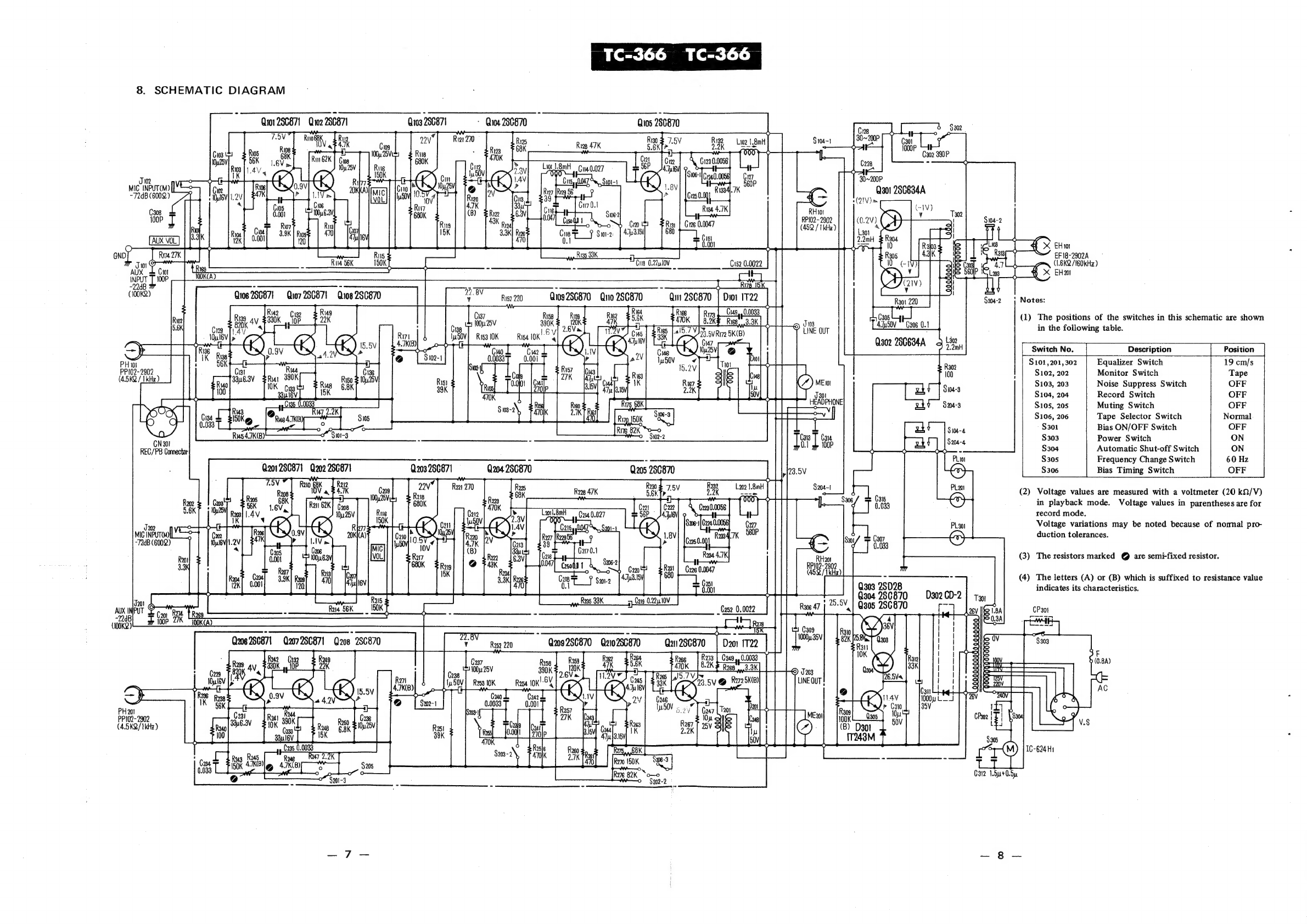
8.
SCHEMATIC
DIAGRAM
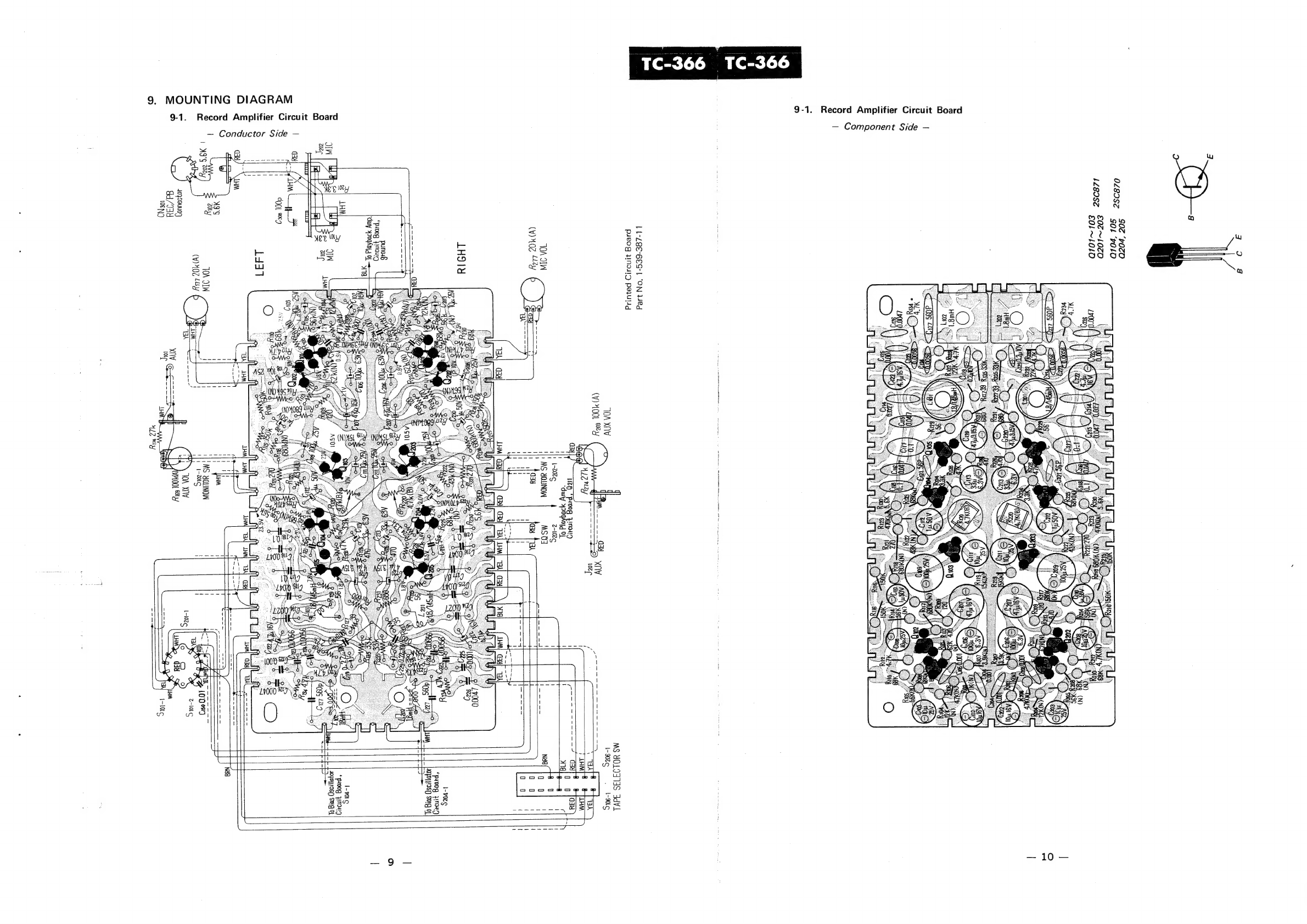
9.
MOUNTING
DIAGRAM
9-1.
Record
Amplifier
Circuit
Board
.........
9~10
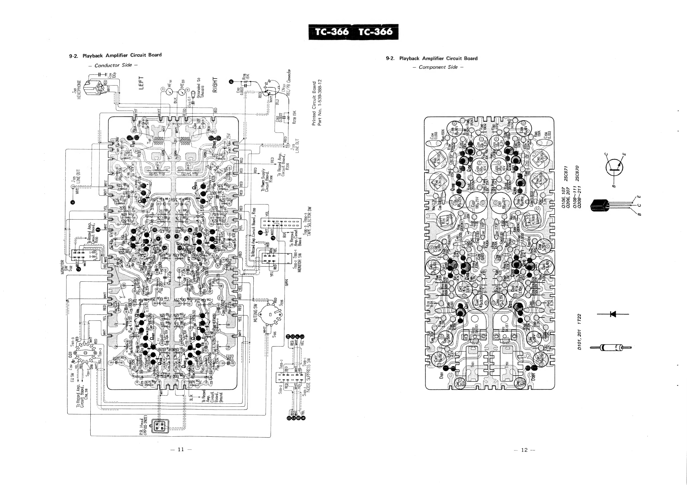
9-2.
Playback
Amplifier
Circuit
Board
......
11)
~12
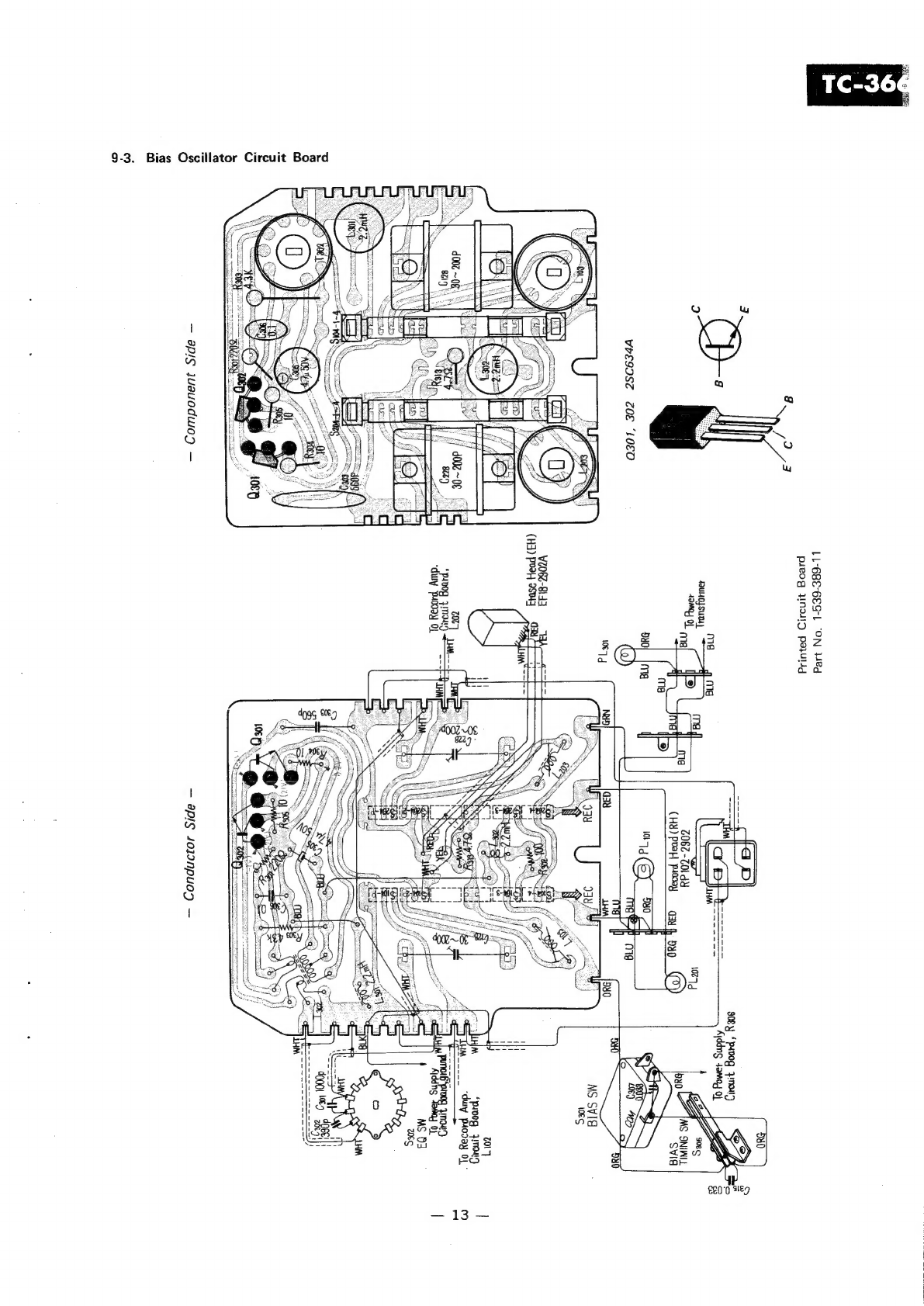
9-3.
Bias
Oscillator
Circuit
Board...
ee
13
9-4,
Power
Supply
Circuit
Board
.......
eee
14
10.
LEVEL
DIAGRAM
uu...
eeeccccce
eee
ceteeeeree
anne
ane
eeaeees
15
1.
GENERAL
DESCRIPTION
The
SONY
Model
TC-366
which
is
the
one-
motor,
three-head
stereo
deck
type
tape
recorder
equips
with
the
following
features,
Tape
Tension
Regulator
The
machine
can
operate
always
under
the
stable
tape
running
by
the
tape
tension
regulator
which
quickly
responds
to
the
subtle
change
of
tape
tension,
so
that
the
tape
tension
regulator
can
reduce
the
wow
and
flutter
extremely.
14.
ELECTRICAL
PARTS
LIST
15.
EXPLODED
VIEW
Title
Page
11.
MECHANICAL
ADJUSTMENT.
................
16
~
24
12.
ELECTRICAL
ADJUSTMENT
.................
25~39
13.
CONVERSION
TO
DIFFERENT
POWER
LINE
FREQUENCY
15-1.
Packing
15-2.
Cabinet
—
top
view
—
15-3.
Amplifier
Chassis
—
top
view
(1)
«++
46
15-4.
Amplifier
Chassis
—
top
view
(2)
—
47~48
15-5.
Head Deck
—
top
view
—_
«--.-
49~
50
15-6.
Chassis
—
top
view
(1)
—
-.:--ee
eee
SI~
52
15-7.
Chassis
—
top
view
(2)
—
.---+
53
~
54
16.
HARDWARES
oo
eesessececcsscecesssesecessessrstseeeneens
55
Hardware
Nomenclature
.........eeeeeeeeeeeeees
55
Automatic
Shut-off
Mechanism
When
threading
the
tape,
the
shut-off
lever
is
held
by
the
threaded
tape
in
operating
position.
If
tape
runs
out
or
breaks,
the
shut-off
lever
swings
outward
and
activates
the
automatic
shut-off
mecha-
nism.
As
a
result,
the
function
selector
knob
can
return
to
the
STOP
position
without
setting
it
manually.
Note:
When
threading
the
tape,
make
certain
that
there
is
no
slack
in
the
threaded
tape,
otherwise
the
function
selector
knob
will
not
be
set
at
the
desired
2.
BLOCK
DIAGRAM
position.
Quy
Qm
Qua
Qua
Qos
ag
Tehet
AME
BIAS.
OSC
Mx
sey
ay
nee
a
A
ic
"
iF
:
V\\
EHX
\
MIG
Ss
i)
——
RH
Sias-e
I
en
OX
H
ll
REC/PB
i
Connec'
Soa
©
LINE
OUT
—
LINE
AMP
—
Qho
On
ME
IE
—o5V]]
Heapprione
——
PLAYBACK
AMP
—
To
Toot
Q393
3
VOLTAGE
REGULATOR
="
as
AC
(NPUT
|
50,
B0Hz
Q304
O05