Sound Devices 664 Manual

664
Portable Production Mixer and Recorder
User Guide and Technical Information
firmware rev. 1.0
Sound Devices, LLC
E7556 State Rd. 23 and 33 • Reedsburg, WI • USA
+1 (608) 524-0625 • fax: +1 (608) 524-0655
Toll-Free: (800) 505-0625
www.sounddevices.com
UDMA


664 User Guide and Technical Information
1
Front Panel Descriptions . . . . . . . . . . . . . . . . . . . . . . . 3
Left Panel Connectors and Control . . . . . . . . . . . . . . . 4
Right Panel Connectors and Controls. . . . . . . . . . . . . 5
Rear Panel Descriptions . . . . . . . . . . . . . . . . . . . . . . . . 6
Screen Overview . . . . . . . . . . . . . . . . . . . . . . . . . . . . . . 6
Main Screen
RTN Screen
Input Setup and Control . . . . . . . . . . . . . . . . . . . . . . . . 7
Input Settings Screen
Phantom Power
Gain/Trim and Fader Relationship
Input Trim
Input Fader
High-Pass Filter
Pan Control
Input Linking
M/S Matrixing
Digital Inputs
Limiters. . . . . . . . . . . . . . . . . . . . . . . . . . . . . . . . . . . . . 12
Metering . . . . . . . . . . . . . . . . . . . . . . . . . . . . . . . . . . . . 13
Meter Ballistics
VU
Peak + VU
Input Activity LED
Headphone Peak LED
Headphone Monitoring . . . . . . . . . . . . . . . . . . . . . . . . 14
Headphone Gain
Headphone Source Selection
Headphone Presets
Headphone Tones
PFL (Channel Solo Monitor)
RTN and COMM Monitoring
Output Setup and Control. . . . . . . . . . . . . . . . . . . . . . 16
Master and Aux Outputs
XLR
TA3 (Master L, R, X1, and X2)
Hirose 10-pin
Direct Outputs
Master and Aux Bus Level
AES Digital Outputs
COM Setup . . . . . . . . . . . . . . . . . . . . . . . . . . . . . . . . . . 18
COM Send Program
Com Program Auto-Mute
Slate/Com Mic & Tone Oscillator . . . . . . . . . . . . . . . . 19
Slate Microphone
Internal Slate Mic
External Slate Mic
Tone Oscillator
Alternate Slate/Com Switch
Digital Audio Recorder . . . . . . . . . . . . . . . . . . . . . . . . 20
Transport Control
Recording Tracks
Track Arming
Track-to-Media Routing
Track Naming
Sampling Rate
Word Clock Synchronization
Bit Depth
Bit Depth and Dynamic Range
Recording Media
Time Code
Timecode modes
Timecode Frame Rate
Jam Menu
F Sampling Rate Modes
Synchronization
File Management
File Type
File Structure
Folder Options
Automatic File Splitting
Metadata Fields
Sound Reports
Take Management
Take List
Take Number
Scene Name
Take Notes and Phrases
Playback
Using a USB Keyboard . . . . . . . . . . . . . . . . . . . . . . . . 32
Mixer Linking . . . . . . . . . . . . . . . . . . . . . . . . . . . . . . . . 33
Linking the 664 With Another 664 or 552 Mixer
Linking to Other Mixers
Linking to a 302 or 442
Linking to a MixPre-D or Original MixPre
Powering. . . . . . . . . . . . . . . . . . . . . . . . . . . . . . . . . . . . 35
External Powering
Internal Battery Powering
Voltage Metering
Power Consumption
Setup Menu . . . . . . . . . . . . . . . . . . . . . . . . . . . . . . . . . 37
Inputs
Outputs
Limiters
Recorder
Comms/Returns
Timecode/Sync
File Storage
System
Quick Setup
Front Panel Button Shortcuts. . . . . . . . . . . . . . . . . . . 43
Connector Pin Assignments . . . . . . . . . . . . . . . . . . . 44
Specifications . . . . . . . . . . . . . . . . . . . . . . . . . . . . . . . 45
Analog Inputs
Analog Outputs
Digital Outputs/Recorder
Timecode and Sync
Power
Environmental
Dimensions and Weight
Accessories . . . . . . . . . . . . . . . . . . . . . . . . . . . . . . . . 48
Wave Agent . . . . . . . . . . . . . . . . . . . . . . . . . . . . . . . . . 49
Declaration of Conformity. . . . . . . . . . . . . . . . . . . . . . 50
Warranty and Technical Support . . . . . . . . . . . . . . . . 51
Table of Contents

664 User Guide and Technical Information
2
v. 1.0 Features and specifications are subject to change. Visit www.sounddevices.com for the latest documentation.
Copyright Notice and Release
All rights reserved. No part of this publication may be reproduced, stored in a retrieval system, or transmitted in any form or by any
means, electronic, mechanical, photocopying, recording, or otherwise, without the expressed written permission of SOUND DEVICES,
LLC. SOUND DEVICES is not responsible for any use of this information.
SOUND DEVICES, LLC shall not be liable to the purchaser of this product or third parties for damages, losses, costs, or expenses
incurred by purchaser or third parties as a result of: accident, misuse, or abuse of this product or unauthorized modifications, repairs, or
alterations to this product, or failure to strictly comply with SOUND DEVICES, LLC’s operating and installation instructions.
Microsoft Windows is a registered trademark of Microsoft Corporation. Macintosh is a registered trademark of Apple Computer. Other
product and company names mentioned herein may be the trademarks of their respective owners.
The sound waves logo is a registered trademark of Sound Devices, LLC.

664 User Guide and Technical Information
3
Front Panel Descriptions
1
2 193
4 75 86 9 10
12
13
14
15161718
11
1) Input Fader
Primary control for adjusting the level of an
input during operation. Ranges from offto +15
dB. Nominal seing is in the middle (0 dB).
2) Gain (Trim)
Coarse input gain control. Sets the initial input
sensitivity level so that the Input Fader can be
used for fine gain adjustments. Range is from
+22 dB to +72 dB. See Input Setup and Control.
3) Highpass Filter Control
Adjusts corner (-3 dB) frequency of high-pass
filter. Full counter-clockwise position (detent-
ed) deactivates the High-Pass Filter. Range is
80-240 Hz, 12 dB/oct to 6 dB/oct. See Input Setup
and Control.
4) PFL / Input Select Switch
Slide left: Pre-Fade Listen. Sends the input’s
pre-fade signal to HP monitor mono mix.
Multiple inputs can be solo’d simultaneously.
Does not affect Master Output signal. Slide the
switch left to activate, and again to deactivate.
For momentary action, hold the switch left for
one second or longer. The Input LED flashes
yellow when an input’s PFL is active. Slide
right: Input Seings. Enters the Input Seings
Screen where basic input setup and input-to-
output bus routing is performed. See Input
Setup and Control.
5) Input LED
Indicates input signal activity. Illuminates in
various colors and intensities to show signal
level and activity. Green = signal presence (pre-
fader), yellow = limiter activity (pre- and post-
fade), red = signal overload/clipping (pre- and
post-fade), flashing yellow = input PFL.
6) Input Pan
Controls the Left/Right balance of the input
signal to the Stereo Master Bus.
7) Recorder Control
Controls the Integrated Digital Recorder. Slide
up to Record, press in to Pause/Stop, slide
down to Play, slide left to Rewind, slide right
to Fast Forward. See Digital Audio Recorder.
8) Meter Button
Displays the Main Screen which includes me-
tering, filename, time code and other important
information. Also toggles between inputs 1-6
and returns A,B and C metering. Returns to
Main Screen from any other Screen.
9) LCD
Displays contextual operating information and
user interface.
10) Internal Timecode LED
When the 664 is powered down, the Internal
Timecode LED will flash blue to indicate that
timecode is being maintained. The 664 will
hold accurate timecode for 2 hours after being
powered down.
11) Power Switch
Three-position slide switch, selects between AA
baery power or external DC sources, middle
position is off.
12) Power LED
Illuminates green to indicate the 664 is pow-
ered on.
13) Menu Button
Displays the Setup Menu.

664 User Guide and Technical Information
4
v. 1.0 Features and specifications are subject to change. Visit www.sounddevices.com for the latest documentation.
14) Headphone Encoder
Meter and Input Seings ScreView: Turn to ad-
just headphone gain. Push to select headphone
monitor source. In Menus turn to navigate.
Push to make selection. In Input Seings Screen
push to select input source.
15) Headphone Clipping LED
Illuminates red to indicate headphone output is
approaching clipping level.
16) RTN Switch
Slide Left to activate RTN A, slide Right to
activate RTN B. To access secondary function
Press and hold Select Encoder then slide left for
COM RTN and right for RTN C. Primary and
Secondary functions of the RTN toggle switch
can be selected in the Setup Menu.
17) Slate / Tone Switch
Slide left to activate the Slate Microphone, slide
again to deactivate. For momentary action
hold for one second or longer. Slide right to
activate the Tone Oscillator. Tone will latch
if held for 2 seconds or longer; slide again to
deactivate. Secondary function: press and hold
Select Encoder then slide Mic switch to activate
COM. Primary and Secondary functions can be
switched in the Setup Menu.
18) Slate Mic LED
Illuminates green when Slate Mic, COM, or
Tone is active.
19) Select Encoder
Multi-function encoder. Selects Tracks on the
Main Screen. Press the Encoder and the Meters
buon to arm/disarm record tracks. When L,
R, X1, or X2 track is selected, press then turn
to adjust level. Select Encoder also acts as shift
buon to access secondary functions.
Left Panel Connectors and Control
1
4 3 2
1) XLR Analog Inputs 1-6
Active-balanced analog microphone- or line-
level input for inputs 1-6 on XLR connector. In-
put type is set within the Input Seings Screen.
Inputs 1 and 6 can also accept AES3 or AES42
signal. Pin-1 ground, pin-2 (+), pin-3 (-).
2) Headphone Output
1/4-inch and 3.5 mm TRS stereo headphone
connectors. Can drive headphones from 8 to
1000 ohm impedances to very high levels. Tip =
left, ring = right, sleeve = ground.
3) Slate Mic Input
TA3 input for connecting external slate mi-
crophone. Select between internal or exter-
nal slate mic from the Setup Menu section
COMMS/RETURNS. Pin-1 ground, pin-2 (+),
pin-3 (-).
4) TA3 Direct Outputs 1-6 / Inputs 7-12
Balanced direct outputs on TA3 connectors. Tone
signal appears at the direct outputs. Direct output
signal is pre- or post-fader and level is selected
between Line, -10, and Mic levels in the Setup Menu
section OUTPUTS. With the CL-6 Input Expander
aached, these connections can be selected as analog
line inputs 7-12. Pin 1 = Ground; pin 2 = Hot (+); pin
3 = Cold (-) float pin 3 to unbalance.

664 User Guide and Technical Information
5
Right Panel Connectors and Controls
1 2 3 4 5 6 7
8
910111213
1) USB B Connector
Factory use and keyboard connection (with
adapter).
2) Timecode Input
Time code input and output on 5-pin LEMO®
connector.
3) 10-pin A and C
Each connection includes a pair of transformer-
isolated Outputs and a stereo unbalanced
Return input. Analog Output levels are selected
between Line, -10, and Mic levels in Setup
Menu section OUTPUTS. 10-pin A outputs can
be set to AES Outputs 5,6 and 7,8 in the Setup
Menu section OUTPUTS.
4) Tape Output
Unbalanced stereo, tape level output on TA3
(Pin 1 = Ground, pin 2 = Left, pin 3 = Right) and
3.5 mm (Sleeve = Ground, Tip = Left, Ring =
Right) connector.
5) X1 and X2 Outputs
Line, -10, or Mic level selected in the Setup
Menu section OUTPUTS. Pin 1 = Ground,
pin 2 = Hot (+), pin 3 = Cold (-) float pin 3 to
unbalance.
6) TA3 Master Outputs
Line, -10, or Mic level selected in the Setup
Menu section OUTPUTS. Pin 1 = Ground,
pin 2 = Hot (+), pin 3 = Cold (-) float pin 3 to
unbalance.
7) Link I/O
Used to link additional Sound Devices 664, 552,
302, 442, or MixPre mixers.
8) Battery Compartment
Holds five AA (LR6) baeries for backup pow-
ering. NiMH rechargeable cells advised.
9) DC Input
Accepts DC voltages from 10–18 V for power-
ing. Pin 1 = Negative (–), pin 4 = Positive (+).
Ext DC is fully isolated (floating) from the rest
of the circuitry.
10) XLR Master Outputs
Transformer-balanced analog outputs on stan-
dard 3-pin XLR connectors. Pin 1 = Ground;
pin 2 = Hot (+); pin 3 = Cold (-). Unbalance by
grounding pin 3 to pin 1. Can be set to send
AES3 digital signals (1,2 and 3,4 on L and R
respectively) in Setup Menu section OUTPUTS.
11) RTN B Input
Unbalanced stereo 3.5 mm female connector for
Return B audio input. Sleeve = Ground, Tip =
Left, Ring = Right.
12) CompactFlash Slot
Accepts CompactFlash cards with the label-side
toward the rear of the 664. Compatible with
Type I and Type II cards. High-speed UDMA
cards are recommended for higher track count
recording.
13) SD Card Slot
Accepts SD/SDHC/SDXC cards with the
notched corner oriented toward the top of the
664. High speed class 10 cards are recommend-
ed. Insert until it clicks securely in the slot. The
card should glide smoothly into the slot. Push
to eject.
664 User Guide and Technical Information
6
v. 1.0 Features and specifications are subject to change. Visit www.sounddevices.com for the latest documentation.
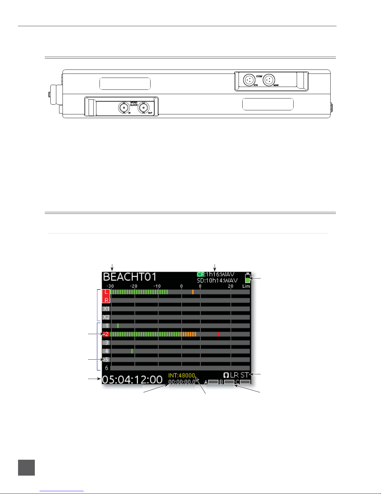
Rear Panel Descriptions
1) BNC Word Clock Input
Accepts word clock rates between 32 kHz and
48.048 kHz for synchronizing the internal re-
corder to external digital audio devices.
2) BNC Word Clock Output
Provides word clock signal to synchronize
external digital audio devices to the 664.
3) TA3 COM Send
Unbalanced, stereo, line-level output. Program
assigned to COM output from Setup Menu.
4) TA3 COM Return
Line-level input for return feed from on-set
communications sources.
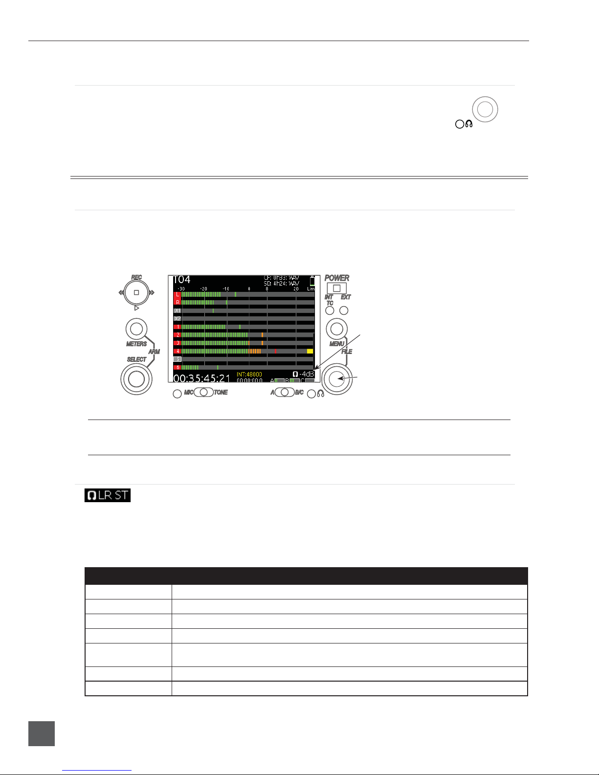
Screen Overview
Main Screen
The Main Screen displays important information at-a-glance. The Main Screen can be accessed quickly
from any other screen by pressing the Meters buon.
Input tracks
Bus tracks
Armed track
Current take Media information
Power source level
Sample rate information RTN levels
Monitor (Headphone) information
SMPTE Timecode
Absolute recording time
Unarmed track
664 User Guide and Technical Information
7
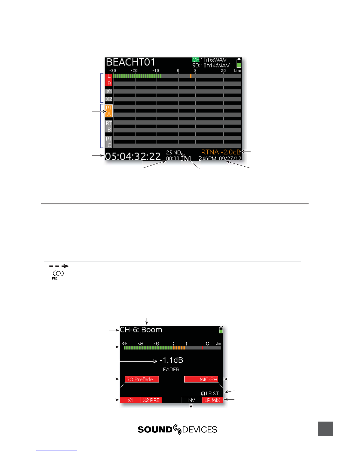
RTN Screen
When the Meters buon is pressed from the Main Screen, the RTN Screen is shown.
Return inputs
Bus tracks
RTN during gain adjustment
Return gain (during adjustment)
SMPTE Timecode
Timecode frame rate Time and dateAbsolute recording time
Input Setup and Control
The 664 has six, full-featured audio inputs on XLR connectors (six additional inputs on TA3 connec-
tors with the optional CL-6 Input Expander aached). Each analog input has a wide gain range to
accommodate nearly all signal types, from microphones to line-level sources. Inputs can be used as ei-
ther balanced or unbalanced connections. To unbalance, tie pin-3 to pin-1 of the XLR connector. There
is no change in gain between unbalanced and balanced connections into the 664.
Input Settings Screen
Each input’s seings are accessed through its Input Seings Screen. To access the Input Seings screen
for an input, slide the Input Selector Switch to the right. The LCD will display information pertaining
to the selected input and provide access to .
2) Input Meter
Input/Track Number
input/Track Name
6) Input Polarity
1) ISO Track Status
4) Aux Bus Assignment
3) Input Selection
Headphone Source / Level
5) LR Bus Assignment
Current Fader Gain

664 User Guide and Technical Information
8
v. 1.0 Features and specifications are subject to change. Visit www.sounddevices.com for the latest documentation.
1) ISO Track Status
Displays the status of the Input’s dedicated Iso Track on the recorder. Each input is permanently
routed to its Iso track. To select whether an input is routed pre- or post-fade, push the Select Encoder,
turn it to make a selection, and push it again to confirm the selection.
The background color of the Iso Track Status box indicates the status of the Input’s Iso Track. A blue
background indicates that the Iso Track is not active and will not be recorded. A red background indi-
cates the Iso Track is armed for recording.
2) Input Meter
Displays the Input’s signal level and limiting activity. The level displayed is the level to the Iso Track
and will be pre- or post-fade depending on the Iso Track Status. Meter ballistics can be set globally
from VU or Peak+VU in Setup Menu item SYSTEM > Meter Ballistics.
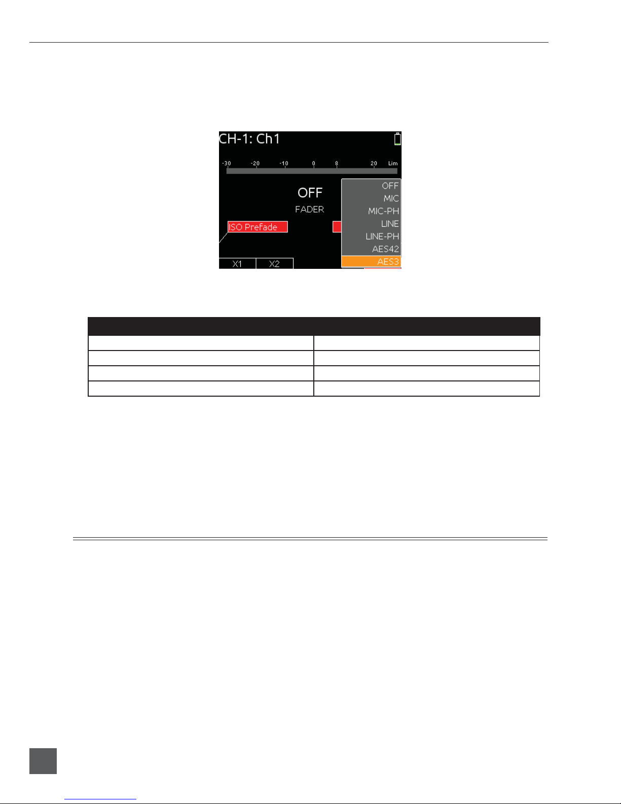
3) Input Selection
Displays the available input types. To change the input type, push the Headphone Encoder, turn it to
make a selection, and push it again to confirm the selection.
Input Type Description
Off Input off.
MIC Use with dynamic microphones or other mic-level signals.
MIC-PH Use with phantom-powered condenser microphones only. Provides 48V or 12V phantom power.
see Phantom Power
LINE For use with any line-level source.
LINE-PH For use with phantom-powered condenser microphones only. Provides 48V or 12V phantom
power, but at a line-level gain range. Useful for recording extremely loud sounds.
AES42 Digital input with power activated for digital microphones, inputs 1, 2, 5, and 6 only.
AES3 Digital input, inputs 1, 2, 5, and 6 only
AES42 and AES3 option only appears in input 2 when selected in input 1, and only appears in input 5 when
selected in input 6. Channel 1 and Channel 6 XLR connectors are used for digital inputs.
4) Aux Bus Assignment
Displays the status of the Input’s assignment to the X1 and X2 Output Buses. Inputs 2 through 5 can
only be routed to X1 and X2 pre-fade, while Inputs 1 and 6 can be routed to X1 and X2 pre- or post-
fade. Slide the Slate / Tone Switch left for the X1 Track and right for the X2 Track to cycle through the
available options.

664 User Guide and Technical Information
9
5) LR Bus Assignment
Displays the status of the Input’s assignment to the main Left and Right Output Buses. Inputs routed
to the Left and Right Output Bus are always post-fader and post-pan. To add or remove the Input
from the Left and Right Output Bus, slide the RTN Switch to the right.
6) Input Polarity (Inputs 2, 4, and 6)
Polarity reversal is used to compensate for incorrectly wired balanced cables, to prevent signal cancel-
lation when a source is dual-miked from opposite directions, or to reverse left/right with microphones
in a mid-side (MS) configuration.
Phantom Power
Phantom powering is a fixed DC voltage of either 12 or 48 Volts. This voltage is resistively applied to
pin 2 and pin 3 of an input’s XLR connector, relative to pin 1. In this configuration, there is no voltage
difference between signal pins 2 and pin 3.
The phantom voltage is selectable between 12 and 48 Volts from the Setup Menu item
INPUTS > Phantom Voltage. The selected voltage level applies to all inputs with phantom power
enabled. The factory default phantom power voltage is 48 V.
Phantom power can be activated for each input. To enable phantom power, enter the input’s chan-
nel screen, press the Headphone Controller, highlight either MIC-PH or LINE-PH, press Headphone
Controller again to make the selection.
Gain/Trim and Fader Relationship
The gain of an input is adjusted by two controls, Input Trim and Input Fader. This two-stage architec-
ture is identical the topology of large mixing consoles and provides a great deal of control. Input Trim
is often thought of as a course gain control and the Input Fader as the fine gain control.
Input Trim
The 664’s input sensitivity is set with the pop-up Trim control knob. With
the Input Fader set to unity gain (0 dB or 12 o’clock), make the appropri-
ate adjustments using the Trim control. Once the coarse gain is set to
the desired level, push the Trim control to hide it from the 664’s mixing
surface. Trim level is adjustable from 22 to 72 dB of gain.

664 User Guide and Technical Information
10
v. 1.0 Features and specifications are subject to change. Visit www.sounddevices.com for the latest documentation.
Input Fader
The Input Fader is the primary control used while mixing and it affects
the level of the Input signal routed to all post-fade destinations. Use the
Input Fader to make fine gain adjustments. The fader can be aenuated
from off(full counter-clockwise position) to +15 dB above the set Trim
level (full clockwise position). To optimize gain structure for the best per-
formance, operate input faders at or near the 0 dB (unity gain) position.
High-Pass Filter
Each input channel has an adjustable high-pass filter controlled by the High-Pass Filter control. High-
pass (or low-cut/low roll-off) filters are useful for removing excess low
frequency energy from audio signals. Wind noise is a common unwanted
low frequency signal that can be reduced with the use of a high-pass filter.
For most audio applications, engaging the high-pass filter is beneficial, be-
cause audio information below 100 Hz is rarely used, especially for speech
reproduction.
The 664’s high-pass filter circuit features an adjustable corner (-3 dB) fre-
quency over a range from 80 to 240 Hz. Below 80 Hz, the filter’s slope is 12
dB/octave. At higher corner frequency seings, the slope is 6 dB/octave. The
purpose for this compound slope is to give additional roll-offat the 80 Hz
seing to reduce wind noise and low frequency rumble. The higher seings
can be used to counteract the proximity effect of directional microphones where a more gentle slope is
desired.
The 664’s high-pass filter circuit is unique because of its placement before any electronic amplification.
Most mixers’ high-pass filter circuits are placed after the microphone preamplifier, such that all of the
low-frequency signals get amplified. By virtue of the 664’s circuit cuing the low-frequency signals
before amplification, higher headroom is achieved in the presence of signals with significant low-
frequency energy.
When possible, aempt to equalize at the sound source with microphone selection, placement, wind-
screens, and onboard microphone filtering. Many microphones have on-board high pass filters. Use
the high-pass filters on the 664 in conjunction with the microphone’s filter to increase the filter’s slope.
The filter can be removed from the circuit completely by rotating the high-pass filter control to the full
counter-clockwise (detented) position. The high-pass filter potentiometer can be adjusted easily and
then recessed to hide it from the mixing surface.
Pan Control
The pop-up Pan Control routes inputs to the left (L) and right (R)
channels of the stereo Master Bus. The pan pot has a detent in the
center position. After seing the pan, the pan control can be recessed
to hide it from the mixing surface during normal operation.
664 User Guide and Technical Information
11
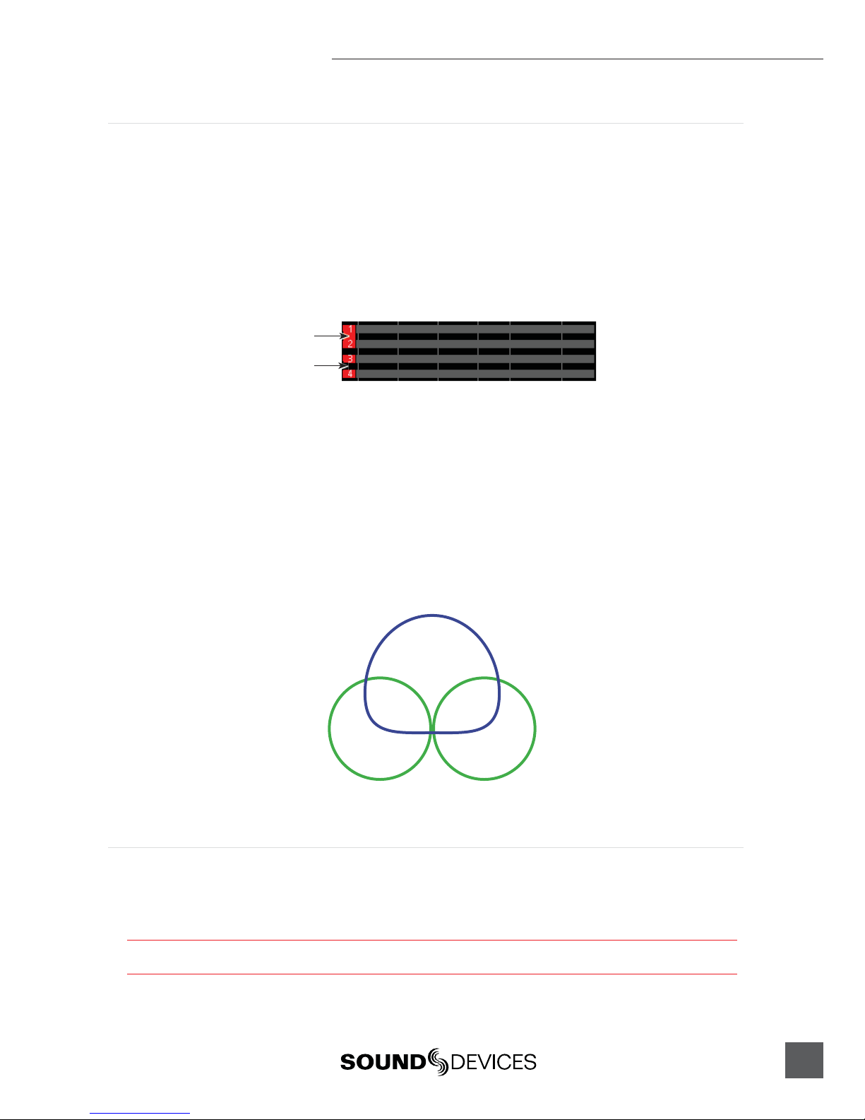
Input Linking
Input pairs 1-2, 3-4, and 5-6 can be linked as stereo pairs. When a pair of inputs is linked:
• Each channels’ Trim Control and High-Pass Filter Control work as normal, controlling coarse
gain and high-pass filtering for their respective inputs.
• The odd channel’s Input Fader controls the post-fade level of both inputs.
• The odd channel’s Pan Control controls the balance of the stereo signal to the Master Bus.
• The even channel’s Fader Control and Pan Control are disabled.
• The limiters of both inputs are linked.
• The background label of both inputs is connected on the Main Screen.
Linked
Unlinked
M/S Matrixing
When input pairs are linked MS, the odd channel is used for the Mid signal and the even channel is
used for the Side signal. To produce a stereo signal from an M/S configuration, the signal from both
microphones must be processed.
Mid-side (MS) matrixing is a method for processing audio signal from a cardioid microphone and a
bidirectional microphone into a stereo signal. The cardioid microphone is the “mid” signal and con-
nects to the odd Input, and the bidirectional microphone is the “side” signal and connects to even In-
put. The cardioid microphone is pointed at the sound source, and the bidirectional microphone is ori-
ented sideways (positioned with its capsule as near as possible to the cardioid microphone’s capsule).
The following diagram shows the relative polar paerns of microphones in an M/S configuration.
Mid Signal
Side Signal
Digital Inputs
The 664 accepts AES3 (AES/EBU) balanced, AES42 (digital microphone) balanced, and AES3id unbal-
anced digital signals on the Input 1 and Input 6 XLR connectors. The 664 auto-detects between AES3
and AES3id digital signals and adjust accordingly. Digital input gain is controlled from the front panel
faders.
Never aach unbalanced connections to an input set for AES42. This can result in damage to the hardware.
664 User Guide and Technical Information
12
v. 1.0 Features and specifications are subject to change. Visit www.sounddevices.com for the latest documentation.
To use a digital input, slide the Input 1 or Input 6 Input Selector Switch to the right to enter the Input
Seings Screen. Press the Headphone Encoder to display the list of available input sources. Turn
the Headphone Encoder to select AES3 or AES42, and press the Headphone Encoder to confirm the
selection.
Each connector carries two channels of digital audio. Alternate channels of digital audio sent to Input
1 or Input 6 are available on adjacent inputs, according to the following table.
AES Input Channel: Available to 664 Input:
XLR Input 1, Left Channel Input 1
XLR Input 1, Right Channel Input 2
XLR Input 6, Left Channel Input 5
XLR Input 6, Right Channel Input 6
The 664’s digital inputs are sample rate converted to the internal recorder’s sample rate. To sync the
sample rate of the 664’s internal recorder to external digital audio devices, see Sampling Rate.
Things to consider when using AES digital inputs:
• When using an unbalanced AES3 (SPDIF) input, the other available digital input should not be
used with an AES42 microphone.
• Signal from digital inputs is not available on direct outputs.
Limiters
Limiters prevent clipping by aenuating signals that surpass a set threshold. The amount of aenua-
tion is defined by the “ratio” of the limiter and expressed as two numbers. All 664 limiters use a 20:1
compression ratio. This means that signal that exceeds the threshold by 20 dB will exit the limiting
stage at only 1 dB above the threshold.
The time it takes for limiting to begin once signal has exceeded the threshold is referred to as the “at-
tack time” and the time it takes for limiting to cease once signal has fallen back below the threshold is
referred to as “release time”. Signals that exceed the threshold faster than the limiter’s aack time can
still cause clipping. The 664 limiters have a 1 ms aack time and a 500 ms release time.
The limiters are globally activated when the Setup Menu item LIMITERS > Limiters is set to On. This
activates both the input and output limiters. Sound Devices recommends using the limiters at all times.
Limiters are present on both mic and line-level inputs as well as the Master L,R tracks and the X1,X2
tracks. The 664 input limiters have a threshold of +16 dBu (4 dB below clipping), while the limiters for

664 User Guide and Technical Information
13
the L, R, X1, and X2 tracks are adjustable from the Setup Menu item OUTPUTS > L,R Limiter Thresh
and OUTPUTS > X1,X2 Limiter Thresh.
In normal operation, with a properly set gain structure, the threshold of the Input Limiter is rarely
reached. Without Input Limiters, high signal conditions can overload a channel and cause distortion.
The Input limiter is working when the respective input’s Input Activity LED illuminates yellow. If the
Activity LED is regularly in the yellow, reduce the amount of gain applied to the channel by turning
down the Trim control. See Input Activity LED for additional information.
When Inputs are linked as a stereo pair, the Input Limiters are also linked and perform the same gain
reduction equally to both inputs.
The Output Limiters prevent the L,R and X1,X2 signal from exceeding the user-set limiter threshold.
Setup Menu options LIMITERS > L,R Limiter Thresh and LIMITERS > X1,X2 Limiter Thresh allow
limiter thresholds to be set set in 1 dB increments from +4 dBu to +20 dBu.
Metering
All track levels are displayed on the LCD in the Main Screen. RTN input levels are displayed on the
RTN Screen (Press the Meters buon to toggle between the RTN Screen and the Main Screen). Each
segment of the meter represents 1 dB. A larger red square under the 20 dBU marker indicates clipping
on the track. A large yellow square indicates limiting activity on the track.
Input clipping
Limiter active
Meter Ballistics
VU
VU (volume units) meter ballistics correspond closely to how the human ear perceives loudness. This
provides a good visual indication of how loud a signal will be. In VU mode, the aack and decay of
the meter signal is 300 mS. VU meters provide good visual indication of how loud a signal will be, but
provide poor information of actual signal peaks.
Peak + VU
The 664 can simultaneously display VU and Peak level information. In this mode the perceived loud-
ness (VU) is displayed as a standard bar, and the Peak signal as a single, independent segment above
the VU.
Input Activity LED
Each Input has its own Input Activity LED located just above the Input Fader.
The LED illuminates in various colors and intensities to represent the signal
level appearing at its respective input. Green = pre-fade signal activity, yellow
= pre- and post-fader limiter activity, red = pre- and post-fader signal overload
(peaking). Reduce the trim level control if the LEDs continuously illuminate
yellow or red. The Input Activity LED will flash yellow when the Input PFL is
latched. see PFL.
664 User Guide and Technical Information
14
v. 1.0 Features and specifications are subject to change. Visit www.sounddevices.com for the latest documentation.
Headphone Peak LED
The Headphone Peak LED is located just left of the Headphone Encoder.
This LED will illuminate red to indicate clipping in the headphone amplifier.
Monitoring without a visual indication of headphone clipping can mislead the
sound mixer into thinking that the output or return feeds are distorted.
Headphone Monitoring
Headphone Gain
Headphone output level is controlled by turning the Headphone Encoder while viewing the Main
Screen or Input Seings Screen. When adjusting the headphone gain, the gain value (in dB) is dis-
played in the lower right corner of the LCD (Near the Headphone Encoder). This space displays the
currently selected headphone source when the headphone gain is not being adjusted.
Headphone Encoder
Headphone gain during adjustment
The 664 can drive headphones to dangerously high volumes. Turn down the headphone gain before
selecting a headphone source to prevent accidental signal extremes.
Headphone Source Selection
To select the monitor source, push the Headphone Encoder while viewing the Main Screen to display
the Monitor Source List. This will display a list of available monitor sources. Turn the Headphone
Encoder to highlight a source, and press the Headphone Encoder to select that source. The signal to
the headphone outputs will immediately change to the selected program.
Monitor Source Description
LR ST Master Bus in stereo.
LR Mono Master Bus summed mono to both ears.
L Mono Left channel of Master Bus sent to both ears.
R Mono Right channel of Master Bus sent to both ears.
LR MS ST Mid-Side Stereo - Master Bus decoded MS stereo to headphones, this is not to be used if the inputs
are already linked as an MS pair.
X1X2 Aux Bus in stereo.
HP Preset HP Presets 1-6 are customizable monitor sources. See Headphone Presets
664 User Guide and Technical Information
15
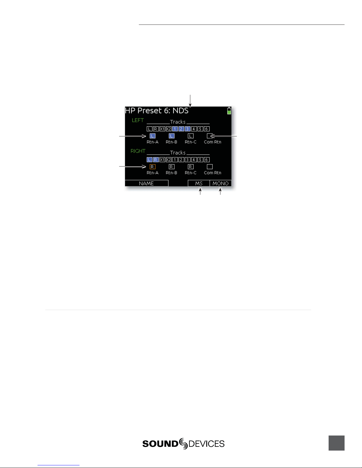
Headphone Presets
Six custom monitor sources are available. These headphone presets can be edited, named and saved.
To edit a custom headphone preset, press the Headphone Encoder to access the Monitor Source List,
highlight the desired preset, then slide the Slate/Tone Switch. This displays the Headphone Preset
Screen:
Highlighter
Assigned source Unassigned source
HP Preset name
MS decoding Mono summing
Available sources are displayed for each monitor channel (left and right). Sources with a blue back-
ground are assigned to that channel of the headphones, and sources with a black background are not
assigned to the headphone channel. To toggle the assignment of a source, turn the Headphone Encod-
er to highlight the source and press the Headphone Encoder to toggle the assignment.
Slide the RTN Switch left to toggle MS decoding for the preset. MS decoding will decode the entire
preset and should not be used if inputs are already linked MS. Slide the RTN Switch right to toggle-
mono summing of the preset. Mono summing will ignore left and right assignment and put all active
sources in both channels of the preset.
When the Headphone Preset is edited, it can be named so it can be easily identified in the Monitor
Source List. To name a Headphone Preset, slide the Slate / Tone Switch either left or right while view-
ing the Headphone Preset Screen.
Headphone Tones
The start of a recording is indicated audibly by a single 440 Hz tone sent to headphones. When
recording is stopped two 220 Hz tones are sent to the headphones. The Record/Stop Bell can
be enabled from the Setup Menu item SYSTEM > Record/Stop Bell. The Setup Menu option
SYSTEM > Warning Bell Level allows adjustment of the level of the Record/Stop Bell.

664 User Guide and Technical Information
16
v. 1.0 Features and specifications are subject to change. Visit www.sounddevices.com for the latest documentation.
PFL (Channel Solo Monitor)
Slide the PFL switch left to activate, and again to deactivate. For momen-
tary action, hold the switch left for one second or longer.
PFL stands for “Pre-Fade Listen”. When any input’s PFL is activated, the
currently selected monitor source is replaced with the PFL mix program.
The PFL mix program is a mono mix of the pre-fade level of all inputs
with PFL enabled. PFL monitoring only affects the headphone monitor, it
does not affect audio sent to the outputs.
The selected input’s Activity LED flashes yellow when the input’s PFL is
engaged. When one input PFL is engaged, that input’s name will appear
in the lower right corner of the Main Screen. When multiple input PFL’s
are engaged, PFL MULT will appear in the lower right corner of the Main
Screen.
RTN and COMM Monitoring
RTN A, RTN B, RTN C, and COM RTN inputs can be monitored quickly using the RTN Switch.
Primary Monitor Sources are monitored by sliding the RTN Switch left or right while Alternate
Monitor Sources are monitored by holding the Select Encoder then sliding the RTN Switch left or
right. The Primary and Alternate Monitor Sources can be changed from the Setup Menu options
COMMS/RETURNS > RTN Toggle Left and COMMS/RETURNS > RTN Toggle Right. To return to
the previous monitor selection, Slide the RTN Switch in the same direction of the active RTN.
Output Setup and Control
The 664 features a host of analog and digital outputs to accommodate for complex, multi-camera set-
ups. The 664 has 2 stereo output busses: The Master Bus (LR), and the Aux Bus (X1/X2).
Master and Aux Outputs
There are 4 pairs of balanced analog output connections for the Master Bus (XLR, TA3, and 2 Hirose
10-pin), and one pair of balanced analog output for the Aux Bus (TA3). Additionally, there are two
stereo unbalanced outputs for the Master Bus (TA3 and 3.5mm Tape Outputs).
The XLR and both Hirose 10-pin outputs are transformer-balanced, each driven from their own trans-
former windings for excellent isolation. Each output can be independently set to Line (+4 dBu nomi-
nal), -10, or Mic level (40 dB of attenuation versus Line) from the Setup Menu section OUTPUTS. The
master outputs are capable of driving long cable runs.
XLR
By default the XLR outputs send a balanced analog signal. These connections can be independantly
configured to send AES3 signal. see AES Digital Outputs for details. When set to analog output, the L
and R XLR connections always carry the Left and Right Master Bus program.
TA3 (Master L, R, X1, and X2)
The TA3 outputs send a balanced analog signal. The X1 and X2 TA3 connections always carry X1
and X2 Aux bus program. The L and R TA3 connections always carry the Left and Right Master Bus
program.

664 User Guide and Technical Information
17
Hirose 10-pin
Each Hirose 10-pin connection has a balanced pair of outputs that carry the Left and Right Master bus
program. By default, each of the balanced outputs on the Hirose 10-pin connections sends a balanced
analog signal. Each of the balanced outputs on the 10-pin A connections can be independantly config-
ured to send AES3 signal. see AES Digital Outputs for details.
Each Hirose 10-pin also includes an unbalanced stereo return input for headphone monitoring. The
Sound Devices XL-10 Breakout Cable is an available accessory that provides easy access to the bal-
anced outputs and stereo returns of the 10-pin Hirose connections.
Direct Outputs
Inputs 1-6 have corresponding direct outputs on balanced TA3 connections. By default, these out-
puts are pre-fade and line level. The direct outputs can be set to post-fade from the Setup Menu item
OUTPUTS > Direct Out Pre/Post. The direct outputs can be set to Line (+4 dBu nominal), -10, or Mic
level (40 dB of attenuation versus Line) from the Setup Menu item OUTPUTS > Direct Out Levels.
AES digital input signals are not available on direct outputs.
Master and Aux Bus Level
The output gain of the Master Bus and the Aux Bus is adjustable from Off, -30 to 0dB. To adjust output
gain:
1. From the Main Screen, turn the Select Encoder to highlight the output(s) to be aenuated.
2. Push the Select Encoder. The output level of the highlighted track will be displayed in the
lower right-hand corner of the LCD. If no adjustment is made before 3 seconds, the selection will
cancel. This is to avoid accidental adjustments.
3. Turn the Select Encoder to adjust the gain.
Outputs that are linked (from Setup Menu item OUTPUTS > Linking) will be shown as a connected
box on the Main Screen and their gain will be adjusted simultaneously.
AES Digital Outputs
There is a total of 8 available channels of digital output on 4 connections. Each of the XLR or 10-
pin A outputs can be configured to output AES3 digital signals from the Setup Menu options
OUTPUTS > XLR-R Out, OUTPUTS > XLR-L Out, and OUTPUTS > 10-pin A Out.
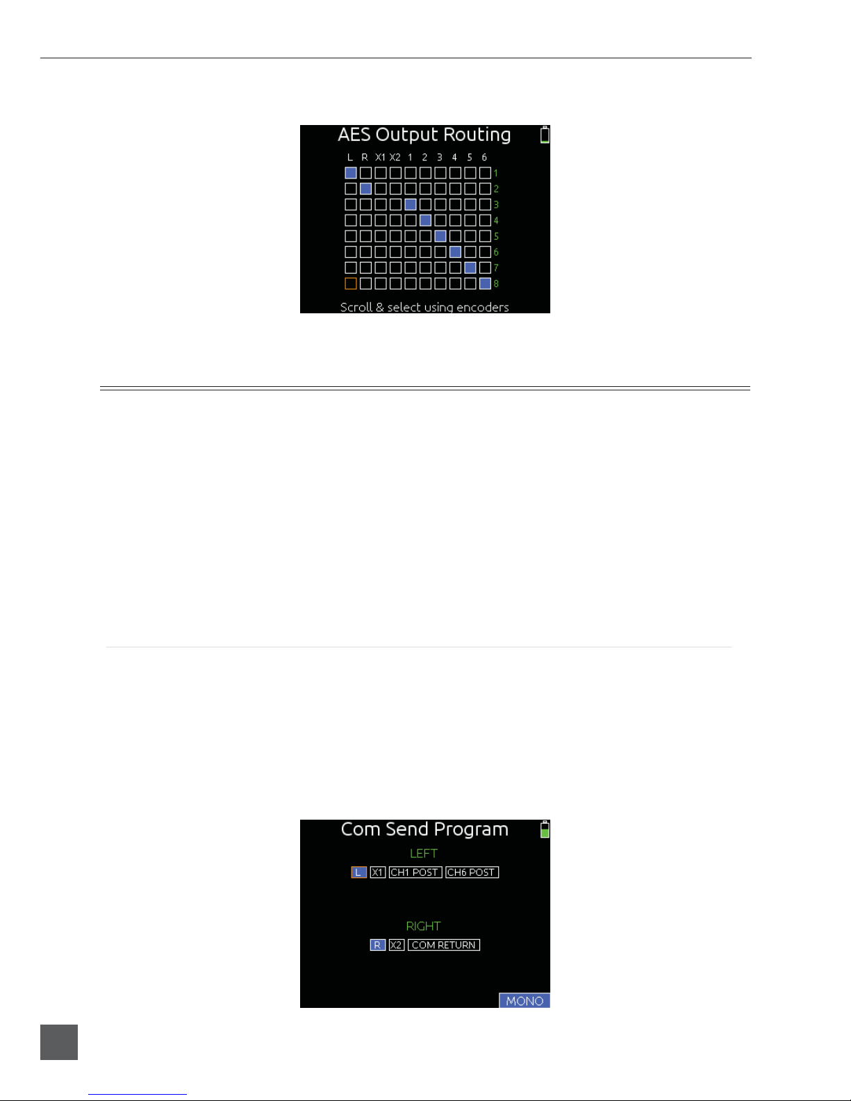
Any track can be routed to any AES output in any combination. The AES output routing can be edited
from the Setup Menu item OUTPUTS > AES Output Routing. This interface consists of a matrix in
which the columns are tracks and the rows are the numbered AES outputs. The blue boxes indicate
routed tracks and the black boxes indicate unrouted tracks. Turn the Select Encoder to move the
orange highlighter vertically and turn the Headphone Encoder to move the highlighter horizontally.
Push either the Select Encoder or the Headphone encoder to toggle the routing status of the highlight-
ed track.
664 User Guide and Technical Information
18
v. 1.0 Features and specifications are subject to change. Visit www.sounddevices.com for the latest documentation.
The following screen shot shows the AES Output Routing screen. The highlighter is in the lower-left
corner.
COM Setup
The 664 features an unbalanced stereo COM Send (TA3) and an unbalanced stereo COM RTN (TA3)
for communications purposes. These special input and output channels can be used to privately com-
municate with a boom operator or other member of the production crew.
During operation, it is possible to interrupt the Com signal and speak to the boom operator via the
slate mic by Holding down the Select Encoder and sliding the Slate/Tone Switch to the left. The green
Slate LED will illuminate to indicate that the slate mic is routed to the Com Send. During this time, the
slate mic signal is sent only to the Com Send Output and right Headphone output, but not to record
tracks or any other outputs. To cancel slate communication and resume the Com Program, slide the
Slate/Tone Switch to the left again. The green Slate LED will turn off.
The gain of the Com Send and Com Return can be adjusted from the Setup Menu options
COMMS/RETURNS > Com Send Gain and COMMS/RETURNS > Com Return Gain, respectively.
COM Send Program
By default, the program sent to the COM Send output is the Left and Right Stereo Bus. To change the
program of the COM Send:
1. Enter the Setup Menu and select COMMS/RETURNS.
2. Select the Com Send Program Option.
3. Turn the Headphone Encoder to select the desired source, and push the Headphone Encoder
to toggle the assignment of the source to the Left or Right side of the COM Send.
4. Optionally, slide the RTN switch to toggle mono or stereo of the COM Send.
Other manuals for 664
6
Table of contents
Other Sound Devices Music Mixer manuals

Sound Devices
Sound Devices 552 User manual

Sound Devices
Sound Devices MixPre Manual

Sound Devices
Sound Devices 552 Manual

Sound Devices
Sound Devices 688 User manual

Sound Devices
Sound Devices MixPre-10M User manual

Sound Devices
Sound Devices 633 User manual

Sound Devices
Sound Devices 664 User manual

Sound Devices
Sound Devices 633 User manual

Sound Devices
Sound Devices 664 User manual

Sound Devices
Sound Devices 664 User manual


