Sound Devices 552 Manual

552 Packing List
Thank you for purchasing the 552 Five-Channel Portable Production Mixer with Integrated Recorder.
Please make certain that this package contains the listed items below.
1) 552 Five-Channel Portable Production Mixer with Integrated Recorder
1) Printed User Guide and Technical Information
4) Rubber Bumpers
6) Colored Dots
1) Purchase Registration Card
1) Setup Menu Chart Card
1) Front Panel Shortcuts Card
1) Packing List (this sheet)
February, 2014


552
Five-Channel Portable Production Mixer
with Integrated Recorder
User Guide and Technical Information
firmware rev. 1.4
Sound Devices, LLC
E7556 State Rd. 23/33 • Reedsburg, WI • USA
+1 (608) 524-0625 • fax: +1 (608) 524-0655
Toll-Free: (800) 505-0625
www.sounddevices.com
support@sounddevices.com


552 User Guide and Technical Information
1
Quick Start Guide .......................3
Front Panel Descriptions .................8
Rear Panel Descriptions ................11
Left Panel Connectors and Controls ......11
Right Panel Connectors and Controls .....12
Top and Bottom Panels..................13
Voice Prompt ..........................13
Input Setup and Control .................14
Mic/Line Selection
Phantom Power
Gain - Trim and Fader Relationship
Input Trim
Input Fader
High-Pass Filter
Pan Control
Input Polarity
Stereo Linking
Stereo Pair Linking
MS Pair Linking
Input Muting
Output Setup and Control ...............19
Master Gain Control
Master Outputs
XLR
TA3
Hirose 10-Pin
Direct Outputs
Tape Outputs
Mono Mic Output
AES Digital Outputs
Limiters...............................21
LIM and LINK
Digital Audio Recorder ..................22
File Format
WAV (Broadcast WAV)
MP3
Bit Depth
Bit Depth and Dynamic Range
Sampling Rate
Sampling Frequency and Audio Bandwidth
Recording Media
Folder Structure
File Naming
Automatic File Splitting
Recorder Controller
REC LED
Record Mode
Record Pause
Time Code
Time Code to Track
External Time Code Auto Record
Playback
Metering ..............................29
Meter Ballistics
VU
Peak
Peak + Peak Hold
Peak + VU
Peak Hold + VU
Meter Reference Level
Zoom Metering
Input Activity LED
Headphone Peak LED
Headphone Monitoring ..................31
Headphone Gain
Headphone Source Selection
Headphone Tones
Record Start and Stop Tones
Playback Navigation Tones
PFL (Channel Solo Monitor)
RTN A and B
Split Ear Return Monitoring
Powering .............................33
Internal Battery Powering
External Powering
Voltage Metering
Power Consumption
Slate Mic/Tone Oscillator ................34
Slate Microphone
Tone Oscillator
Talk Back Mode ........................35
Time of Day/Date Clock..................37
Mixer Linking ..........................37
Linking 552 Mixers
Linking to Other Mixers
Linking to a 302 or 442
Linking to a MixPre
Accessing the Setup Menu...............39
User Settings
Factory Default Settings
Setup Menu Chart ......................40
Front Panel Button Shortcuts ............42
Connector Pin Assignments .............44
Specifications .........................45
Block Diagram - Inputs and Outputs .......48
Block Diagram - Monitoring ..............49
Block Diagram - AES....................50
Accessories ..........................51
Wave Agent ...........................52
CE Declaration of Conformity ............53
Warranty and Technical Support ..........54
Table of Contents

552 User Guide and Technical Information
2
v. 1.4 Features and specifications are subject to change. Visit www.sounddevices.com for the latest documentation.
Welcome
Thank you for purchasing the 552 Mixer. It is the next evolutionary step in professional, portable
audio mixers. With a core design based on the legendary 442, it contains countless improvements
and added flexibility.
Developed with insight from the industry’s top audio engineers, the 552 Field Mixer encompasses
the audio performance, feature set, and mechanical construction demanded by those who rely on
audio gear for their livelihood. The 552 contains five high-performance microphone preamplifiers,
multiple outputs including AES outputs, comprehensive monitoring, and a high-quality built-in
audio recorder. Its input and output flexibility, including pre- or post- fade direct outputs on each
channel, make the 552 at home in small “run-and-gun” applications as well as large, multiple input
productions.
The 552 incorporates a complete feature-set into a compact, functional design. 552 features are ac-
cessible from the three main surfaces. The Setup Menu can be accessed at anytime to make changes
to various parameters. The highly efficient circuitry allows the mixer to be powered by either four
internal AA batteries or external 10-18 VDC.
With a two-track recorder on-board, sound mixers can rest assured that audio is being recorded lo-
cally. The 552 records polyphonic Broadcast Wave or MP3 files to removable, Secure Digital (SD) or
Secure Digital High Capacity (SDHC) cards.
The 552, like all Sound Devices professional audio products, is designed to withstand the physical
and environmental extremes inherent to field production. Its compact construction strikes the perfect
balance between performance, accessible controls, and durability.
Copyright Notice and Release
All rights reserved. No part of this publication may be reproduced, stored in a retrieval system, or transmitted in any form or by any
means, electronic, mechanical, photocopying, recording, or otherwise, without the expressed written permission of SOUND DEVICES,
LLC. SOUND DEVICES is not responsible for any use of this information.
Microsoft Windows is a registered trademark of Microsoft Corporation. Macintosh is a registered trademark of Apple Computer. Other
product and company names mentioned herein may be the trademarks of their respective owners.
The sound waves logo is a registered trademark of Sound Devices, LLC.
Limitation of Liability
LIMITATION ON SOUND DEVICES’ LIABILITY. SOUND DEVICES, LLC SHALL NOT BE LIABLE TO THE PURCHASER OF THIS
PRODUCT OR THIRD PARTIES FOR DAMAGES, LOSSES, COSTS, OR EXPENSES INCURRED BY PURCHASER OR THIRD PAR-
TIES AS A RESULT OF: ACCIDENT, MISUSE, OR ABUSE OF THIS PRODUCT OR UNAUTHORIZED MODIFICATIONS, REPAIRS,
OR ALTERATIONS TO THIS PRODUCT, OR FAILURE TO STRICTLY COMPLY WITH SOUND DEVICES, LLC’S OPERATING AND
INSTALLATION INSTRUCTIONS. TO THE FULLEST EXTENT PERMITTED BY LAW, SOUND DEVICES SHALL HAVE NO LIABILITY
TO THE END USER OR ANY OTHER PERSON FOR COSTS, EXPENSES, DIRECT DAMAGES, INCIDENTAL DAMAGES, PUNITIVE
DAMAGES, SPECIAL DAMAGES, CONSEQUENTIAL DAMAGES OR OTHER DAMAGES OF ANY KIND OR NATURE WHATSOEVER
ARISING OUT OF OR RELATING TO THE PRODUCTS, THESE TERMS AND CONDITIONS OR THE PARTIES’ RELATIONSHIP,
INCLUDING, WITHOUT LIMITATION, DAMAGES RESULTING FROM OR RELATED TO THE DELETION OR OTHER LOSS OF AUDIO
OR VIDEO RECORDINGS OR DATA, REDUCED OR DIMINISHED AUDIO OR VIDEO QUALITY OR OTHER SIMILAR AUDIO OR
VIDEO DEFECTS ARISING FROM, RELATED TO OR OTHERWISE ATTRIBUTABLE TO THE PRODUCTS OR THE END USER’S USE
OR OPERATION THEREOF, REGARDLESS OF WHETHER SUCH DAMAGES ARE CLAIMED UNDER CONTRACT, TORT OR ANY
OTHER THEORY. “CONSEQUENTIAL DAMAGES” FOR WHICH SOUND DEVICES SHALL NOT BE LIABLE SHALL INCLUDE, WITH-
OUT LIMITATION, LOST PROFITS, PENALTIES, DELAY DAMAGES, LIQUIDATED DAMAGES AND OTHER DAMAGES AND LIABILI-
TIES WHICH END USER SHALL BE OBLIGATED TO PAY OR WHICH END USER OR ANY OTHER PARTY MAY INCUR RELATED TO
OR ARISING OUT OF ITS CONTRACTS WITH ITS CUSTOMERS OR OTHER THIRD PARTIES. NOTWITHSTANDING AND WITHOUT
LIMITING THE FOREGOING, IN NO EVENT SHALL SOUND DEVICES BE LIABLE FOR ANY AMOUNT OF DAMAGES IN EXCESS
OF AMOUNTS PAID BY THE END USER FOR THE PRODUCTS AS TO WHICH ANY LIABILITY HAS BEEN DETERMINED TO EXIST.
SOUND DEVICES AND END USER EXPRESSLY AGREE THAT THE PRICE FOR THE PRODUCTS WAS DETERMINED IN CONSID-
ERATION OF THE LIMITATION ON LIABILITY AND DAMAGES SET FORTH HEREIN AND SUCH LIMITATION HAS BEEN SPECIFI-
CALLY BARGAINED FOR AND CONSTITUTES AN AGREED ALLOCATION OF RISK WHICH SHALL SURVIVE THE DETERMINATION
OF ANY COURT OF COMPETENT JURISDICTION THAT ANY REMEDY HEREIN FAILS OF ITS ESSENTIAL PURPOSE.

552 User Guide and Technical Information
3
Quickstart
Quick Start Guide
This Quick Start Guide provides a brief overview for first use of the 552.
1) Connect power.
For internal powering from AA batteries, unscrew the battery cap (counter-clock-
wise), insert four AA batteries (not included) positive (+) side first into the battery
tube. Thread the battery cap back on (clockwise). For external powering, connect a
DC powering source (not included) to the DC connector on the Right Panel.
External Power Supply (not included)
AA
+-AA
+-AA
+-AA
+-
2) Connect analog microphone or line sources to the XLR inputs.
552 Left Panel
3) Connect headphones to either the 1/4-inch or the 3.5 mm headphone outputs.
552 Right Panel
4) Power On the mixer.
Slide the power switch to the INT position to power the mixer from AA batteries.
Slide the power switch to the EXT position to power the mixer from external DC.
Slide left for Internal AA Battery
Slide right for External DC Power

552 User Guide and Technical Information
4
v. 1.4 Features and specifications are subject to change. Visit www.sounddevices.com for the latest documentation.
Quickstart
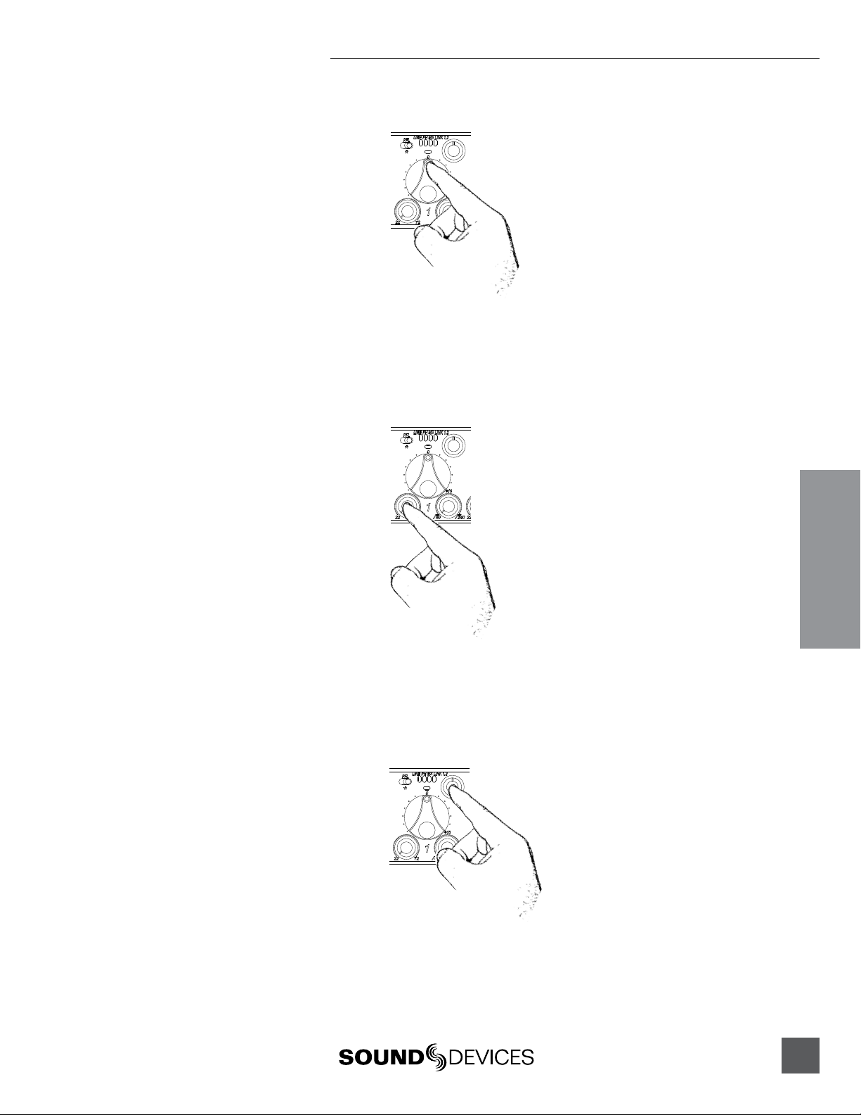
5) Set Input Type – Mic or Line Level.
To select an input to Mic or Line level, hold an input’s PFL switch, then slide the
SLATE MIC/TONE switch to the left. The input’s LINE LED illuminates blue when
set to line level and the LED is not illuminated when set to Mic level.
1) Hold the Input’s PFL. 2) Slide the SLATE MIC/TONE switch left.
6) Apply Phantom Power to an input.
The 552 supplies 48 V to inputs set to receive phantom power (PH). Phantom pow-
er can be set to 12 V in the Setup Menu. To apply phantom power, hold an input’s
PFL switch, then slide the SLATE MIC/TONE switch to the right. The input’s PH
LED illuminates blue when phantom power is applied.
1) Hold the Input’s PFL. 2) Slide the SLATE MIC/TONE switch right.
7) Select a headphone monitor mode using the Headphone Selector.
Stereo (Left and Right) Program
Right Program
Left Program
Stereo MS (mid-side)
Recording Source
Mono (summed left and right)
L
R
M
ST
MS ST
REC Source
MS Monitor Modes are useful to listen to left/right stereo when M and S signals are routed. When
inputs are linked as an MS pair in the Setup Menu use the ST (Stereo program) monitor mode; this will
already contain the decoded MS Stereo signal.
8) Set the headphone level.
Turn the Headphone Controller to set headphone levels. The currently selected
headphone level is briefly indicated on the right output meter when the Head-
phone level control is turned.
552 User Guide and Technical Information
5
Quickstart
9) Set Input Faders in use to unity gain (0 dB or 12 o’clock).
Faders not used should be set to off (full counter-clockwise position).
10) Set Input Trim Levels.
Push to release the recessed Trim (gain) Control. Turn the Trim Control clockwise to
raise the level of the input. Once the gain has been set, push the Trim Control again
to recess the control and remove it from the mixing surface. Use the Input Fader to
make fine level adjustments.
11) Route each input to either Left or Right Outputs using the Input Pan Control.
Push to release the recessed Pan Control. Turn counter-clockwise to send the input
to the Left Output and turn clockwise to send it to the Right Output. Once the pan
has been set, push the Pan Control again to recess the control and remove it from
the mixing surface.
12) Set High-Pass Filters and Limiters.
Set the High-Pass Filter using the control adjacent to the Trim Control (full counter-
clockwise position is off). Activate the Limiters using the switch adjacent to the
Master Output Gain Control (Lim (dual Mono) Link (Stereo) applies to all inputs
and outputs).

552 User Guide and Technical Information
6
v. 1.4 Features and specifications are subject to change. Visit www.sounddevices.com for the latest documentation.
Quickstart
13) Adjust LED Meter brightness.
Press and hold the Battery Check button while turning the Headphone Controller.
14) Check Internal and External power levels.
Press the Battery Check button to display the internal and external power levels
on the Output Meter LEDs. The internal AA battery level is displayed on the left
meter and external DC voltage level is displayed on the right meter.
15) Connect the 552 analog outputs to the next device in the signal chain (audio
recorder, wireless transmitter, or camera).
Output levels are set (Line, -10, Mic) using the respective output’s attenuation
switch.
552 Right Panel
16) Set the next device’s input sensitivity to receive the supplied signal.
17) Activate the 552’s Tone Generator.
Slide the SLATE MIC/TONE switch to the TONE position. Tone latches on if the
switch is held for two seconds; slide right again to turn off. A 1 kHz tone is gener-
ated and is sent out at 0 dB (level and frequency are menu-adjustable).
Slide left for Slate Mic
Slide right for Tone.
18) Adjust the input gain on the next device accordingly.
552 User Guide and Technical Information
7
Quickstart
Voice Prompt
The 552 features a Synthetic Voice for Enhanced Navigation, or SVEN. SVEN provides spoken word
feedback when Setup Menu features are adjusted. He is designed to simplify control and provide
important information to the user. Additionally, SVEN provides status information about the digital
audio recorder and time and date information. SVEN is routed only to the headphone outputs.
19) Setting the Time and Date.
Press and hold the Battery Check button for the mixer to announce in headphones
the current time and date. If the setting spoken back in headphones is incorrect see
Time of Day/Date Clock section of the 552 User Guide.
20) Insert an SD memory card into the back panel SD Slot.
Remove the protective rubber cover to access the SD memory card slot. Insert the
SD card into the slot until it sits securely in the slot. The card should glide smoothly
into the slot. Do not use excessive force when inserting the card and make certain
that the electrical contacts are facing downwards. Push on the card to remove it.
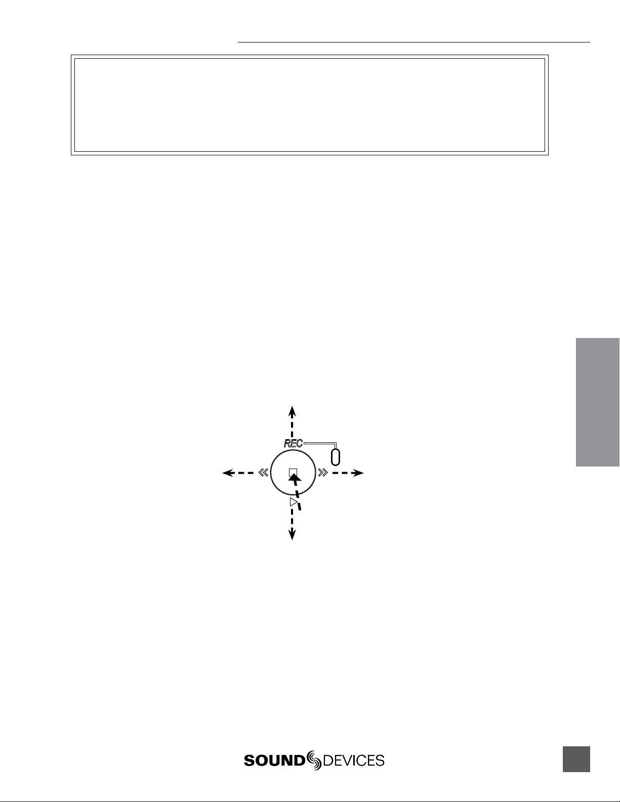
21)Controlling the Integrated Digital Recorder.
The Recorder Controller is used to initiate the Record, Stop, Playback, Rewind, Fast
Forward functions as well as to navigate through recorded files.
Press in to Pause/Stop
Push left to load the previous file.
Push left to Rewind during playback.
Push right to load the next file.
Push right to Fast Forward during playback.
Push down to playback the last recorded file or loaded file.
Push up to begin recording.
22) Making Changes in the Setup Menu.
The 552 has many features that are accessed through its Setup Menu. For details on
entering and controlling the Setup Menu see Accessing the Setup Menu section in
the 552 User Guide.
23) Power Down the Mixer.
Slide the power switch to the center position to power down. All settings are saved
to EEPROM and will be saved and recalled upon next power on whether or not the
unit is powered or has batteries.

552 User Guide and Technical Information
8
v. 1.4 Features and specifications are subject to change. Visit www.sounddevices.com for the latest documentation.
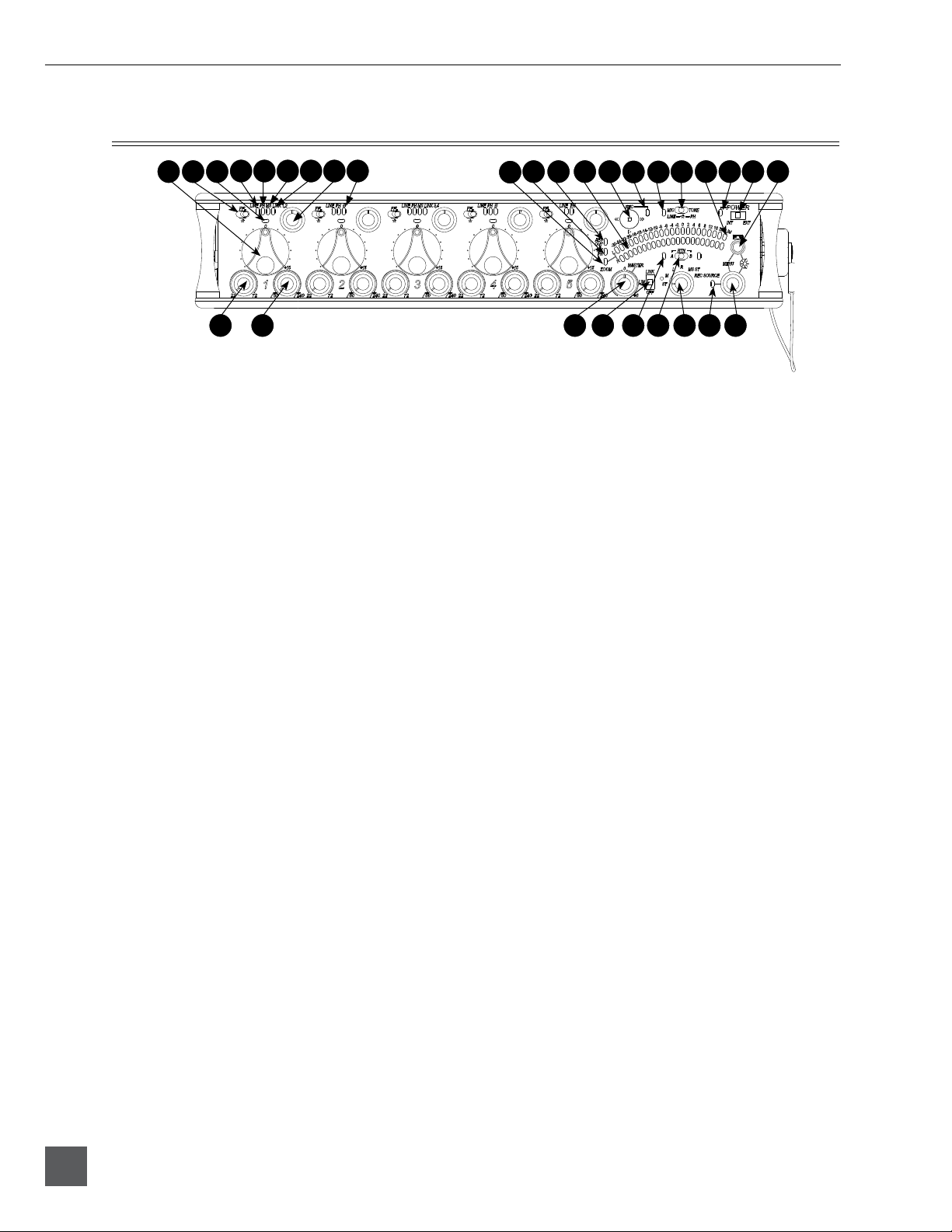
Front Panel Descriptions
All 552 settings are accessed and controlled from the Front Panel. This allows the unit to be placed in
a production bag while having complete control of the unit.
1
2 3 24 25 2726 28 29 30
12 20 21 22 23
19
13 14 15 16
46 7 8 119 10 17 18
5
1) Input Fader
Primary control for adjusting the level
of an input during operation. Ranges
from Off to +15 dB. Nominal setting is
in the middle (0 dB).
2) Gain (Trim)
Coarse input gain control. Sets the
initial input sensitivity level so that the
Input Fader can be used for fine gain
adjustments. Range is from +22 dB to
+72 dB. See Input Setup and Control.
3) High-Pass Filter Control
Adjusts corner (-3 dB) frequency of
high-pass filter. Full counter-clockwise
position (detented) deactivates the
High-Pass Filter. Range is 80-240 Hz,
12 dB/oct to 6 dB/oct. See Input Setup
and Control.
4) PFL/Input Solo Switch
Pre-Fade Listen. Sends the input’s
pre-fade signal to headphones for solo
monitoring, troubleshooting, and gain
setting. Does not affect Master Output
signal. Slide the switch left to activate,
and again to deactivate. For momen-
tary action, hold the switch left for one
second or longer. The Input Signal Ac-
tivity LED flashes yellow when an in-
put’s PFL is latched on. The Input PFL
Switch is also used to make changes to
several input settings. See Input Setup
and Control.
5) Input Signal LED
Indicates input signal activity. LEDs il-
luminate in various colors and intensi-
ties to show signal level and activity.
Green = signal presence (pre-fader),
yellow = limiter activity (pre- and post-
fade) also flashes when solo is latched
on, red = signal overload/clipping
(pre- and post-fade) also solid when
input is muted. See Metering.
6) Mic/Line LED
Illuminates blue to indicate an input is
set to Line level. To toggle between Mic
and Line settings, hold the input PFL
then slide the Slate Mic/Tone Switch to
the Slate position.
7) PH/Phantom LED
Illuminates blue to indicate an input’s
phantom power is on. To toggle phan-
tom power on and off, hold the selected
input’s PFL switch then slide the Slate
Mic/Tone switch to the Tone position.
Phantom power voltage can be set to
12 or 48 V (48 V is Factory Default).
Phantom voltage is set in the Setup
Menu. The phantom power voltage is
applied across all inputs with the PH
LED illuminated.
8) MS LED
Inputs 1, 2 and 3, 4 can be linked as an
MS pair. When a pair is linked, the MS
and LINK LED illuminate blue. Stereo
linking configurations are selected in
the Setup Menu. See Stereo Linking.

552 User Guide and Technical Information
9
9) Link LED
Illuminates blue when Inputs are linked
as a stereo pair. Stereo linking configura-
tions are selected in the Setup Menu. See
Stereo Linking.
10) Input Pan
Controls the Left/Right balance of the
input signal to the outputs.
11) Input Polarity (Inputs 2 and 4 only)
Illuminates blue when the Input’s polar-
ity is reversed. To toggle the state of the
input polarity, hold the selected input’s
PFL then press the Battery Check button.
12) Zoom LED
Illuminates blue when the Output Meter
is in Zoom Mode. Zoom Mode allows
the user to view higher resolution in the
0 to +20 dBu range on the Output Meter.
To toggle Zoom on and off, press in on
the Headphone Controller. The Zoom
Function is defeated in the Setup Menu
Function Meter Ballistics. See Metering.
13) Time Code LED
Time Code is selected from the Setup
Menu. When on, the LED flashes blue
when Time Code is active but not being
received The LED Illuminates solid blue
when the unit is receiving valid time
code. Time Code is connected to the
RTN B TA3 connector and is stamped to
files generated by the 552’s recorder. See
Time Code.
14) AES Out LED
Illuminates blue when one or more of
the AES outputs is active. See Digital
Outputs.
15) Output Meter
Multi -segment LED output meter. Scale
is normally -30 dBu to +20 dBu. In Zoom
Mode, scale changes from 0 dBu to
+20 dBu. To engage Zoom mode, press
in on the Headphone Controller. See
Metering.
16) Recorder Controller
Controls the Integrated Digital Re-
corder. Record Mode is enabled in the
Setup Menu. When enabled, push up
to Record, press in to Pause/Stop, push
down to Play, push left to Rewind, push
right to Fast Forward. See Digital Audio
Recorder.
17) Record LED
Indicates the status of the recording me-
dia. The LED is off when the recorder is
in standby mode. Flashes yellow when
no SD card is inserted. Illuminates solid
red while recording, flashes red when
record is pending. Illuminates solid
green while in playback mode. Flashes
green while playback is paused. Illumi-
nates solid yellow when media is busy.
The LED is off when recorder is off.
18) Slate/Tone LED
Illuminates yellow when either the slate
mic or tone is latched on.
19) Slate Mic/Tone Switch
Slide left to activate the Slate Micro-
phone, slide again to deactivate. For
momentary action hold for one second
or longer. Slide Slate Mic/Tone switch
right to activate the Tone Oscillator. Tone
will latch if held for 2 seconds or longer,
slide again to deactivate. This switch
also functions as input type and phan-
tom power select. See Tone Oscillator/
Slate Mic. See also Talk Back for additional
features.
20) Limiter LED
Each Output has its own Limiter LED.
The LEDs Illuminate yellow when the
Output Limiter is active. See Output
Limiter.
21) Power LED
When powering with internal AA bat-
teries, the LED illuminates green when
the 552 is on, turns yellow when low
voltage point is reached, and flashes
red when voltage reaches a critical level
and batteries should be changed. When
powering with external DC, the LED
illuminates green when the 552 is on,
flashes red when voltage drops below
the set threshold. See Powering.
552 User Guide and Technical Information
10
v. 1.4 Features and specifications are subject to change. Visit www.sounddevices.com for the latest documentation.
Front Panel Descriptions cont.
1
2 3 24 25 2726 28 29 30
12 20 21 22 23
19
13 14 15 16
46 7 8 119 10 17 18
5
22) Power Switch
Three-position slide switch, selects be-
tween internal battery power or external
DC sources, middle position is Off.
23) Battery Check Button
Press to display internal and external
voltage levels on the Output Meter.
Secondary function acts as shift key for
various front panel features. Press and
hold to announce card space available
and current time and date.
24) Master Output Level Control
Controls the overall signal level of the
Master Stereo Outputs. Adjustable from
off to +6 dB. See Outputs.
25) Limiter Switch
Activates both Input and Output Limit-
ers. When LIM is selected, the Output
Limiters act independently on the Left
and Right Outputs. When LINK is
selected, the Output Limiters are linked
and limiting is applied evenly across the
Stereo Outputs. See Limiter.
26) RTN A/B LED
Indicates the activity for each return
input. The LEDs illuminate in various
colors and intensities to indicate the be-
havior of the return signals. Green = re-
turn signal presence, Red = return signal
overload/clipping, Yellow = the monitor
return is latched on. When time code is
active, the TA3 input is used exclusively
for time code. The 3.5 mm jack functions
normally. See Return.
27) RTN A/B Switch
Two-position momentary switch. Slide
left for RTN A headphone monitoring,
slide right for RTN B headphone moni-
toring. Slide again to deactivate. For mo-
mentary action, hold for one second or
longer. While holding the return switch,
turn the Headphone Controller to adjust
RTN A and RTN B levels. When time
code is active, the TA3 input is used ex-
clusively for time code. The 3.5 mm jack
functions normally. See Return and also
RTN Loopback and Time Code.
28) Monitor Selection Switch
Selects program sent to the headphone
monitor. ST = stereo program, M =
mono summed mix of Left and Right
program, L = mono mix of Left program,
R = mono mix of Right program, MS
ST = decoded MS Stereo, REC Source =
program routed to the recorder (AES A).
See Headphones.
29) Headphone Peak LED
Illuminates red when the headphone
monitor is approaching clip levels.
30) Headphone Controller
Controls headphone gain. Secondary
functions include Setup Menu control,
Zoom Mode, LED Brightness adjust-
ment, and Return levels control.
552 User Guide and Technical Information
11
Rear Panel Descriptions
1 2
1) SD Slot
Protective rubber cover for SD (Secure
Digital) memory card slot. Insert the
SD/SDHC card into the slot until it sits
securely in the slot. The card should
glide smoothly into the slot. To remove
the card, push to eject. MMC and SDXC
cards are not supported.
1) Factory Programming Port
Mini USB port used for initial factory
programming. This connection has no
user function.
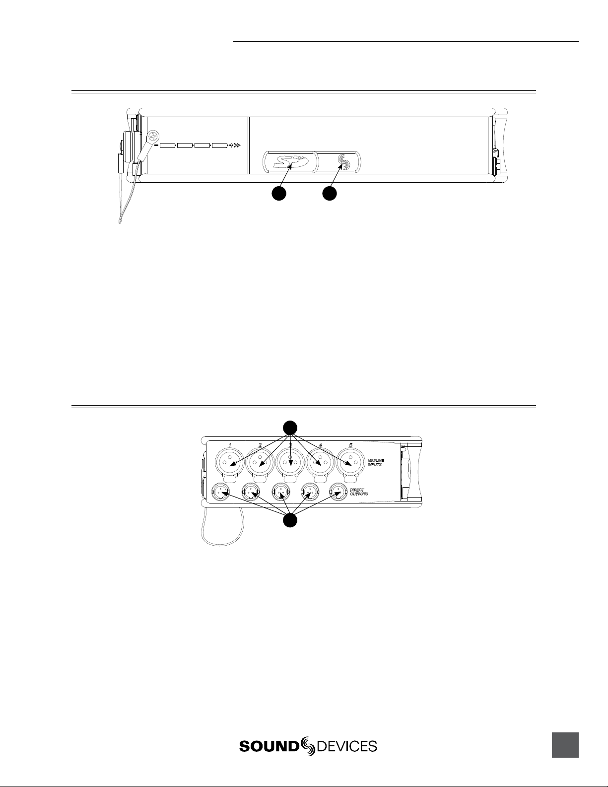
Left Panel Connectors and Controls
1
2
1) Analog Inputs Channels 1-5
Transformer-balanced analog micro-
phone- or line-level inputs 1-5 on XLR
connectors. Pin 1 = Ground; pin 2 = Hot
(+); pin 3 = Cold (-). For unbalanced
inputs, tie pin 1 and pin 3 together =
ground, pin 2 = positive. Make cer-
tain phantom power is off when using
unbalanced inputs. See Input Setup and
Control.
2) Analog Direct Outputs
Balanced direct outputs on TA3 con-
nectors. Slate Mic and Tone signals
appear at the direct outputs. Direct
output signal is pre- or post-fader and
level is selected in the Setup Menu be-
tween Line, -10, and Mic levels. Pin 1 =
Ground; pin 2 = Hot (+); pin 3 = Cold (-)
float pin 3 to unbalance.

552 User Guide and Technical Information
12
v. 1.4 Features and specifications are subject to change. Visit www.sounddevices.com for the latest documentation.
Right Panel Connectors and Controls
1 2 3 4 5 6 7 8 9
10 11 12 13 14
1) Mono Mic Out
Unbalanced mono mic-level output on
3.5 mm female connector, designed to
connect to wireless IFB transmitters or
transcription recorders. Tip = Hot (+),
Sleeve = Ground.
2) Tape Out
Unbalanced stereo output on 3.5 mm
female connector. Sleeve = Ground,
Tip = Left, Ring = Right.
3) RTN B In
Unbalanced stereo 3.5 mm female con-
nector for Return B audio input. Sleeve
= Ground, Tip = Left, Ring = Right. See
RTN B and RTN Loopback Mode.
4) 10-Pin Output Level Switch
Selects the Hirose 10-Pin Output level
between Line, -10, or Mic levels.
5) 10-Pin Master Outputs and Return A
10-pin connector includes second master
output (transformer-isolated from the
XLR outputs) and unbalanced stereo
Return A. Can be set to send out AES
digital signals. See AES Digit Outputs.
6) RTN B / TC Input
Unbalanced stereo input for Return B
audio and Time Code input on TA3 con-
nector. RTN B wiring pin 1 = Ground,
pin 2 = Left, pin 3 = Right. Time Code
wiring pin 1 and 3 = ground, pin 2 = Hot
(+). See Time Code.
7) TA3 Master Outputs
Line, -10, or Mic level selected in the
Setup Menu. Pin 1 = Ground, pin 2 =
Hot (+), pin 3 = Cold (-) float pin 3 to
unbalance.
8) Tape Output
Unbalanced tape-level stereo output
on TA3 connector. Pin 1 = Ground,
pin 2 = Left, pin 3 = Right.
9) Link I/O
Used to link additional Sound Devices
552, 302, 442, or MixPre mixers. See
Mixer Linking.
10) Headphone Outputs
1/4-inch and 3.5 mm stereo connectors,
drive headphones from 8-2000 ohm
impedances. 3.5 mm connection can be
set in the Setup Menu as an independent
boom operator send. See Talk Back Mode.
11) XLR Output Level
Sets the nominal output level for the
Left and Right XLR Master Output to
Line, -10, or Mic levels.
12) XLR Master Outputs
Transformer-balanced analog out-
puts on standard 3-pin XLR connec-
tors. Pin 1 = Ground; pin 2 = Hot (+);
pin 3 = Cold (-). Unbalance by tieing
pin 3 to pin 1. Can be set to send AES3
digital signals in the Setup Menu. See
AES Digit Outputs.
13) Battery Compartment
Holds four AA batteries required for
internal powering. Accepts Lithium,
Alkaline, and NiMH rechargeable cells.
14) DC Input
Accepts DC voltages from 10–18 V for
mixer powering. Pin 1 = Negative (–),
pin 4 = Positive (+). Ext DC is complete-
ly isolated (floating) from the rest of the
circuitry.
552 User Guide and Technical Information
13
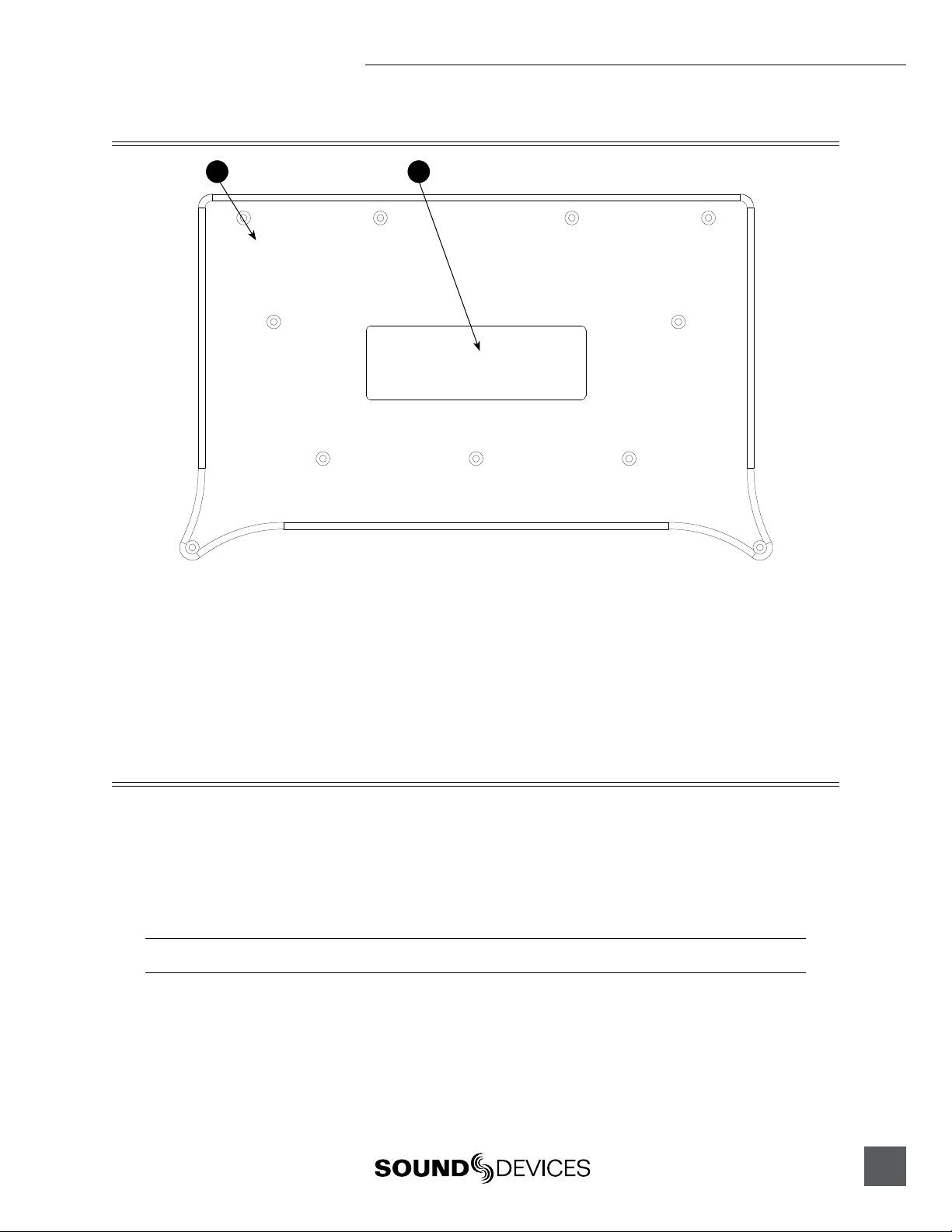
Top and Bottom Panels
1 2
1) Top and Bottom Panels
Made of molded carbon fiber, this highly
specialized composite has nearly identi-
cal strength-to-weight properties as
die-cast magnesium. Additionally, the
material also has the natural RF shield-
ing abilities similar to aluminum.
2) Product Badge
The product badge on the bottom panel
can be covered with a customized iden-
tity tag. The label place holder on the
bottom panel conforms to the 4” x 1.33”
Avery label #5162 standard. Third party
software for Avery label #5162 templates
are available online.
Voice Prompt
The 552 features a Synthetic Voice for Enhanced Navigation, or SVEN. SVEN provides spoken word
information in headphones when Setup Menu features are adjusted. SVEN is designed to simplify
control and provide important information to the user. Additionally, SVEN provides status informa-
tion about the digital audio recorder and time and date information. SVEN is sent only to the head-
phone outputs. If Talk Back Mode is selected, SVEN only appears on the 1/4” headphone output. See
Talk Back for details.
The 3.5 mm headphone output does not receive SVEN announcements when Talk Back Mode is active.
552 User Guide and Technical Information
14
v. 1.4 Features and specifications are subject to change. Visit www.sounddevices.com for the latest documentation.
The following information is reported by the SVEN.
Function Description
Card Space Available Press and hold the Battery Check button to announce the remaining card space available. SVEN
automatically announces remaining record time at 15, 10, 5, and 2 minutes remaining.
Time and Date Continue to hold the Battery Check button after Card Space Available announcement to hear the
current time and date.
Time Date Set Hold Input 5’s PFL then press the Battery Check button and the Headphone Controller to enter
Time Date Set. The unit of time and each value is announced when turning Headphone Controller.
Setup Menu Navigation While in the Setup Menu, the current Function or Option is announced with each turn of the
Headphone Controller.
Playback Navigation Announces the file number of the selected file. If navigating through folders, SVEN announces the
selected daily folder.
Media Busy Indication “Media Busy” is announced if the SD card is not available to respond to a command.
Full SD Card “Full SD Card” is announced when there is no space remaining on the SD card and a record com-
mand has been given.
Record Mode Off “Record Mode Off” is announced if the recorder receives a command and the recorder is disabled
in the Setup Menu.
Next File Press the Recorder Controller in stand-by mode to announce the file number of the next take to
be recorded.
Input Setup and Control
The 552’s inputs consist of five, full-featured preamplifiers. Each input has a wide gain range to ac-
commodate nearly all signal types of microphone and line. The 552 easily accepts signals from low-
sensitivity ribbon and dynamic microphones, medium-level wireless and condenser mic outputs,
and “hot” line-level signals.
The XLR inputs of the 552 are transformer-balanced. The isolation characteristics of transformers are
superior to other balancing techniques and are ideal for the hostile and uncontrolled environments
of field production. Transformers provide galvanic isolation from the driving source, meaning there
is no direct electrical connection. Signals are “transformed” magnetically. The input transformers in
the 552 use premium magnetic core material to achieve high signal-handling-capability (especially at
low frequencies) while keeping distortion to a minimum. Because of their inherently-high common
mode impedance, transformers are unrivaled by any other type of input for common-mode noise
rejection.
The inputs of the 552 can be used as balanced or unbalanced. To unbalance, tie pin-3 to pin-1 of the
XLR connector. There is no change in gain between unbalanced and balanced connections into the
552.
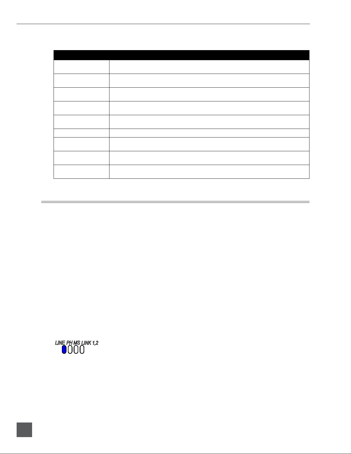
Mic/Line Selection
Two input modes are available, Mic and Line . When Line is selected the LINE LED is illuminated.
Taking into account all gain stages, the 552 has 93 dB of available gain from Mic input to Line output.
When inputs are set to the LINE position, the input sensitivity is reduced by 40 dB.
The selected channel is set to receive a line level input when the Line LED adjacent to the input’s PFL
is illuminated. To toggle between Mic/Line levels, hold the respective input’s PFL and then slide the
Slate Mic/Line switch to the Slate position.

552 User Guide and Technical Information
15
1) Hold the Input’s PFL. 2) Slide the SLATE MIC/TONE switch left.
Phantom Power
Phantom powering is a fixed DC voltage of either 12 or 48 Volts. This voltage is resistively applied to
pin 2 and pin 3 of an input’s XLR connector, relative to pin 1. In this configuration, there is no volt-
age difference between signal pins 2 and pin 3.
The phantom voltage is selectable between 12 and 48 Volts in the Setup Menu. The selected voltage
level applies to all inputs with phantom power enabled. Phantom power voltage is 48V at factory
default. See Setup Menu.
Phantom power can be activated individually for each input. To enable or disable phantom pow-
er, press and hold the respective input’s PFL switch then momentarily slide the Slate Mic/Tone
switch to the Tone position. The respective input’s PH LED illuminates when phantom is enabled.
1) Hold the Input’s PFL. 2) Slide the SLATE MIC/TONE switch right.
Phantom power is only applied to inputs set for Mic level at factory default. Phantom Power can be
applied to inputs set to Line- and Mic-Level in the Setup Menu. This is useful when using micro-
phones in high SPL environments.
Make certain to disable phantom power with Line-level output devices that are susceptible to damage
from DC.
The 552 can provide up to 10 mA to each input at 48 V, sufficient for the most power-hungry con-
denser microphones. Many phantom powered microphones do not require 48 V and can be properly
powered with 12 V. When acceptable, use 12 V phantom to extend the 552’s battery life.
If Phantom Power is not required, for instance with dynamic microphones, it is best practice to dis-
able it. Phantom power can capacitively couple noise into the mic inputs with poor mic cables. When

552 User Guide and Technical Information
16
v. 1.4 Features and specifications are subject to change. Visit www.sounddevices.com for the latest documentation.
disabled, no voltage is applied to the microphone input. Do not apply power to ribbon microphones,
improperly wired cables can permanently damage the microphone.
Gain - Trim and Fader Relationship
The gain of an input is adjusted by two controls, Input Trim and Input Fader. This two-stage archi-
tecture is identical the to topology of mixing consoles and provides a great deal of flexibility. Input
Trim is often thought of as a course gain control and the Input Fader as the fine gain control.
Input Trim
The 552’s input sensitivity is set with the pop-up knob Trim control. With the Input Fader set to unity
gain (0 dB or 12 o’clock), make the appropriate adjustments using the Trim control. Once the coarse
gain is set to the desired level, recess the Trim control to hide it from the 552’s mixing surface. Trim
level is adjustable from 22 to 72 dB of gain.
Input Fader
The Input Fader is the primary control used during mixing operation. Use the Input Fader to make
fine gain adjustments during operation. The fader can be attenuated from off (full counter-clockwise
position) to +15 dB above the set Trim level (full clockwise position). To optimize gain structure for
the best noise performance operate input faders at or near the 0 dB (unity gain) position.
High-Pass Filter
Each input channel has an adjustable high-pass filter controlled by the High-Pass Filter pop-up knob.
High-pass (or low-cut/low roll-off) filters are useful for removing excess low frequency energy from
audio signals. Wind noise is a common unwanted low frequency signal that can be reduced with
the use of a high-pass filter. For most audio applications engaging the high-pass filter is beneficial,
because audio information below 100 Hz is rarely used, especially for speech reproduction.
The 552’s high-pass filter circuit features an adjustable corner (-3 dB) frequency over a range from 80
to 240 Hz. Below 80 Hz, the filter’s slope is 12 dB/octave. At higher corner frequency settings, the
slope is 6 dB/octave. See Specifications. The purpose for this compound slope is to give additional
roll-off at the 80 Hz setting to reduce wind noise and low frequency rumble. The higher settings can
be used to counteract the proximity effect of directional microphones where a more gentle slope is
desired.
When engaged or disengaged, the high-pass filter gradually fades into the selected state. This pre-
vents sudden obvious pops in the audio.
The 552’s high-pass filter circuit is unique because of its placement before any electronic amplifica-
tion. Most mixer’s high-pass filter circuits are placed after the microphone preamplifier, such that all
of the low-frequency signals get amplified. By virtue of the 552’s circuit cutting the low-frequency
signals before amplification, higher headroom is achieved in the presence of signals with significant
low-frequency energy.
Other manuals for 552
3
Table of contents
Other Sound Devices Music Mixer manuals

Sound Devices
Sound Devices 633 Manual

Sound Devices
Sound Devices 664 Manual

Sound Devices
Sound Devices MixPre-10M User manual

Sound Devices
Sound Devices 552 User manual

Sound Devices
Sound Devices 664 User manual

Sound Devices
Sound Devices 664 User manual

Sound Devices
Sound Devices 633 User manual

Sound Devices
Sound Devices 633 User manual

Sound Devices
Sound Devices 664 User manual

Sound Devices
Sound Devices MixPre Manual


