Southwire MAX PUNCH 360 Manual

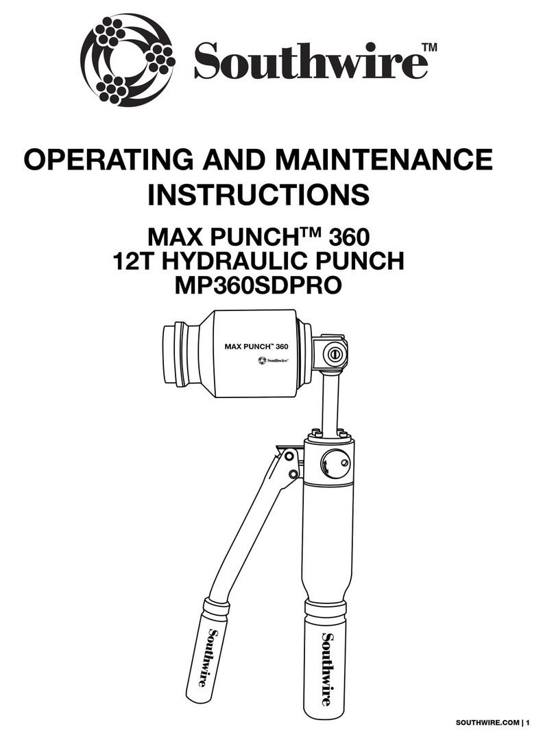
OPERATING and MAINTENANCE
INSTRUCTIONS
MAX PUNCH
TM
360
12T HYDRAULIC PUNCH
(MP360SDPRO)
READ AND UNDERSTAND ALL
INSTRUCTIONS AND SAFETY INFORMATION IN
THIS MANUAL BEFORE OPERATING OR
SERVICING THIS TOOL
08/17
MP360SDPRO Manual

1
TABLE OF CONTENTS
Important Safety Information.................................................2 - 4
Description of Operation.............................................................5
Identification................................................................................5
Setup and Operation..............................................................6 - 7
Product Range Table................................................................. 6
Maintenance...............................................................................8
Warranty...............................................................................9 - 10
SAFETY FIRST
Safety is essential in the use and maintenance of Southwire
Contractor Equipment. This instruction manual and any markings
on the tool provide information for avoiding hazards and unsafe
practices related to the use of this tool. Observe all of the safety
information provided.
SAFETY ALERT SYMBOLS
These symbols are used to call attention to hazards or unsafe
practices related that could result in injury or property damage.
The three safety words defined below indicate the severity of the
hazard. The message after the signal word provides information
for preventing or avoiding the hazard.
2

DANGER:Electrical Shock Hazards.
• Only qualified persons should use MAX PUNCH™360 Hydraulic
Punch.
• Wear eye protection, hard hat, cut resistant gloves and safety
toe shoes when using this tool.
• Do not use tool while tired or under the influence of drugs,
alcohol, or medication.
• Keep body parts and loose clothing away from moving parts.
• Always follow safety procedures as shown in this manual.
• Keep hands clear of cup and cutter when in operation.
• Keep all body parts clear of handle’s path when not is storage
position.
• This is not an insulated tool, contact with live circuits could
result in severe injury or death.
FAILURE TO OBSERVE THESE WARNINGS CAN RESULT
IN SEVERE INJURY OR DEATH
Personal Safety Hazards
WARNING
• Read and understand all instructions and safety information in
this manual before operating or servicing this tool.
IMPORTANT SAFETY INFORMATION
FAILURE TO OBSERVE THESE WARNINGS COULD
RESULT IN SEVERE INJURY OR DEATH
WARNING:Tool Use Hazards
• Use this tool for the manufacturers intended purpose only.
Use other than that described in this manual can result in injury
or property damage.
• Inspect all aspects of the electrical box to ensure safety.
• Only qualified personnel should use knockout equipment.
• Keep all decals clean and legible, and replace when necessary.
CAUTION:
• Read and understand all of the instructions and safety information
in this manual before operating or servicing this tool.
CAUTION:
• Do not use if the cutters are damaged as this can cause binding
leading to tool malfunction.
• If tool is in disrepair, DO NOT USE. Have tool serviced at an
Authorized Southwire Repair Center
Make sure bystanders are clear of the work area when performing
knockouts. Nearby personnel can be injured if there is flying debris.
FAILURE TO OBSERVE THESE CAUTIONS CAN RESULT IN
INJURY OR PROPERTY DAMAGE
FAILURE TO OBSERVE THESE CAUTIONS CAN RESULT IN
INJURY OR PROPERTY DAMAGE
IMPORTANT SAFETY INFORMATION
WARNING:Entanglement Hazard
• Do not operate this tool while wearing loose fitting clothing.
Retain long hair.
• Keep hands away from cup and cutters while operating punch.
Could pinch or crush hands.
• Do not add extensions (cheaters) to the handles. Using
excessive force may result in injury or damage to the tool.
If excessive force is required, check and verify proper set up
instructions.
FAILURE TO OBSERVE THESE WARNINGS CAN RESULT
IN SEVERE INJURY OR DEATH.
34
WARNING:
FAILURE TO OBSERVE THESE WARNINGS CAN RESULT
IN SEVERE INJURY OR DEATH
FAILURE TO OBSERVE THESE WARNINGS CAN RESULT
IN SEVERE INJURY OR DEATH

5
DESCRIPTION OF OPERATION
This manual is intended to familiarize all personnel with the safe
operation and maintenance procedures for the following Southwire
Tools and Equipment: MAX PUNCH™360 HYDRAULIC PUNCH.
Keep this manual available to all personnel. Replacement manuals
are available upon request at no charge at
www.southwiretools.com.
PURPOSE OF THIS MANUAL
The MAX PUNCH™ 360 Hydraulic Punch is a tool that will knockout
½” – 4” diameter holes in mild steel and stainless steel electrical
panels.
6
IDENTIFICATION
PRODUCT RANGE TABLE
SET UP AND OPERATION
1. Draw Stud Input
2. 360 Degree Articulation Head
3. Hydraulic Pressure Valve
4. Hydraulic Cylinder
5. Pump Handle
6. Die Cutter
6. Die Cup
8. ¾” Draw Stud
9. 7/16” Draw Stud
10. ½” Spacer
11. Marksman® Layout Tool
12. Step Bit
1. Use a step bit to drill the pilot holes (Fig. 1).
2. Make sure that the hydraulic pressure valve is in the off position.
3. Screw the draw stud into the articulation head.
NOTE: For ½” punch use 7/16” draw stud, for ¾”-2” punch use
the ¾” draw stud, and for 2-1/2”-4” punch use 1-1/8” draw
stud (Fig. 2).
4. Insert cup onto draw stud facing panel (Fig. 3).
5. Insert draw stud through pilot hole (Fig. 4).
6. Screw on cutter (Fig. 5).
7. Make sure that all three cutter points on the cutter are tight
to the panel.
8. Close pressure valve by turning clockwise to the “ON” position
(Fig. 6).
9. Position the articulation head to a comfortable position.
10. Begin operating the pump handle, stop compressing when
knockout is complete (Fig. 7).
11. Release pressure valve by turning counter clockwise to the
“OFF” position.
12. Unscrew cutter die to release slug (Fig. 8).
MP360SDPRO/MP-03PRO Stainless Steel Knockout

ADDITIONAL HELP
SPECIFICATIONS
• There is a ½” spacer available for convenience but is not
necessary to complete knockout.
• Do not rotate articulating head during the pumping process.
• Release pressure in the hydraulic system when not in use.
MAINTENANCE
Maintain appropriate hydraulic fluid capacity by adding or
changing hydraulic fluid as needed for proper pressure.
Too much hydraulic fluid will cause the MP360HP to
not work properly and may lead to personal injury.
SERVICING
1. Unscrew the hydraulic cylinder.
2. Pinch bladder end with one hand while pulling out the plug
with a pair of pliers.
3. Add hydraulic fluid; leave ½”-1” of space between the
hydraulic fluid level and the end of the bladder.
4. Replace plug.
5. Replace hydraulic cylinder.
Fig. 1 Fig. 2
Fig. 3 Fig. 4
Fig. 5 Fig. 6
Fig. 7 Fig. 8
MODEL # STOCK # DESCRIPTION LENGTH WIDTH DEPTH WEIGHT
MP360SDPRO 58-97-38-01
MAX PUNCH™ 360 Stainless Steel 1/2"-2" Set
21"12" 4" 15lbs
MP-03PRO 57-17-72-01
Large Die Set for Stainless Steel (2-1/2"-4")
In Case (Drive Unit Not Included)
16.5" 13" 4" 24lbs
MP360HP 58-94-63-01 MAX PUNCH™ 360 (Drive Unit Only) 1.5" 5.25" 3.75" 5.5lbs
WARNING:
CAUTION:
7 8

10
Warranty Claim Information/How Do You Get Service?
For all warranty, customer service, and product return authorizations and inquiries,
please contact Southwire’s Tools & Assembled Products at:
Southwire Tools & Assembled Products
840 Old Bremen Road
Carrollton, GA, 30117
Phone Number: 1.855.SW.Tools
Repair Your Product When it is Out of Warranty
Southwire is happy to provide information about where a purchaser can send a product for
repair at consumers’ own expense, please contact 1.855.SW.tools or visit
www.southwiretools.com/tools/home.do for more information about servicing for Southwire
Products.
WARRANTY ON
SOUTHWIRE CONTRACTOR EQUIPMENT
What Does This Warranty Cover?
Five-Year Limited Warranty on Contractor Equipment
Under Southwire’s Contractor Equipment 5-Year Limited Warranty, Southwire Company, LLC
warrants that all Southwire Contractor Equipment will be free from manufacturer defects for a
period of five (5) years from the date of the original end user’s purchase. However, electrical
components and consumable parts such as ropes, blades, dies, draw studs, grips, are
excluded from this 5-Year Limited Warranty and are subject to the One -Year warranty terms.
Under this 5-Year Limited Warranty, the following are also excluded and Southwire
Company, LLC will have no liability for any of the following: normal wear and tear resulting
from product use and damage arising out of misuse, abuse, modification, and improper
product maintenance. This warranty also does not cover Southwire Contractor Equipment
products that have been modified by any party other than Southwire Company, LLC or its
authorized third party designee. This 5-Year Limited Warranty is not transferrable to or
enforceable by any person other than the product’s original end user.
One-Year Limited Warranty on Electrical Components and Consumable
Parts (with 5-Year warranty)
Under Southwire’s 1-Year Limited Warranty, Southwire Company, LLC warrants that all
electrical components and consumable parts such as ropes, blades, dies, draw studs, grips
will be free from manufacturer defects for a period of one-year from the date of the original
end user’s purchase. Under this 1-Year Limited Warranty, Southwire Company, LLC will have
no liability for any of the following: normal wear and tear resulting from product use and
damage arising out of misuse, abuse, modification, and improper product maintenance. This
warranty also does not cover Southwire electrical components and consumable parts that
have been modified by any party other than Southwire Company, LLC or its authorized third
party designee. This 1-Year Limited Warranty is not transferrable to or enforceable by any
person other than the product’s original end user.
Exclusion of Incidental, Consequential, Indirect, Special and Punitive Damages
SOUTHWIRE MAKES NO WARRANTY THAT SOUTHWIRE CONTRACTOR EQUIPMENT PROD-
UCTS WILL BE MERCHANTABLE OR FIT FOR ANY PARTICULAR PURPOSE. SOUTHWIRE MAKES
NO OTHER WARRANTY, EXPRESSED OR IMPLIED, OTHER THAN THE RELEVANT WARRANTY
SPECIFICALLY SET FORTH IN THIS WARRANTY SECTION. SOUTHWIRE WILL NOT BE LIABLE
FOR ANY INCIDENTAL, CONSEQUENTIAL, INDIRECT, SPECIAL, OR PUNITIVE DAMAGES FOR
ANY BREACH OF THIS LIMITED LIFETIME WARRANTY.
Some states do not allow the exclusion or limitation of incidental or consequential
damages, so the above limitation or exclusion may not apply to you.
9
1. All warranty claims must be approved by Southwire’s Tools & Assembled Products
Warranty Department prior to return of product. If Southwire determines that a product is
defective, Southwire will, at its option, repair or replace defective products or defective
product components, free of charge.
2. Upon approval, Southwire will issue a Product Return Authorization Form which will
include instructions on how and where to return the product. The product serial number
and the original date of delivery must be set forth on the Product Return Authorization
Form.
3. Southwire will cover standard freight charges (Ground Courier Rate) incurred in connection
with products that Southwire ultimately determines to be defective.
4. All defective components and defective products that Southwire replaces under these
Warranties will become Southwire’s property and will be retained by Southwire.
Other manuals for MAX PUNCH 360
1
This manual suits for next models
2
Table of contents
Other Southwire Tools manuals
Southwire
Southwire Shoreline Reels RW User manual
Southwire
Southwire HB1A-9 Series User manual
Southwire
Southwire XTS-01 User manual
Southwire
Southwire MAX PUNCH XD Manual
Southwire
Southwire MSP-01 Manual
Southwire
Southwire Triggers TSS-01 User manual
Southwire
Southwire MAX PUNCH 360 Manual

Southwire
Southwire RR-SW45 User manual
