Soyer BMH-30i User manual

1
BMH-30i Operating Instructions
Stud Welder
GB: English Version
Read these operating instructions before starting any work!
Doc.ID: P00234
Date of issue: 08.2015
www.soyer.de

2

3
Operating Instructions
BMH-30i Stud Welder
Serial number*
BMH-30 i Stud Welder_________________________
Please enter the serial number here, so that the data is
immediately available if you need service support.
Order No.
Code designation
Note
P01350
BMH-30i
Mains voltage 3 x 400 V
Heinz Soyer Bolzenschweißtechnik GmbH
Inninger Straße 14 | 82237 Wörthsee | Tel.: +49 8153 8850 | Fax: +49 8153 8030 | E-mail: [email protected]e | www.soyer.de

4
Thank you!
Congratulations on purchasing the BMH-30i SOYER®stud welder.
You have made an excellent choice. Your BMH-30i SOYER®stud welder was specially developed for
the high-speed fastening of SOYER®weld studs in compliance with DIN EN ISO 13918 on metallic,
weldable workpieces.
Our devices have been tested and proven according to current European and national
guidelines on health and safety. Proof of conformity has been established and the
manufacturer is in possession of the corresponding documents.
FOR YOUR SAFETY
Read all of these operating instructions prior to start-up. Please follow all safety
precautions as well as all chapters of these operating instructions before starting
to weld. Non-compliance with the safety precautions can result in serious personal
injuries or death.
SOYER®is a registered trade mark of Heinz Soyer Bolzenschweißtechnik GmbH.
It is prohibited to distribute or reprint this document. It is also prohibited to exploit or disclose its
contents unless permission has been expressly granted. Non-compliance with this regulation will lead
to compensation for damages. All rights reserved, particularly in the case of a patent grant or a GM
registration.
We have verified that the contents of this pamphlet correspond to the hard- and software described.
Deviations, however, cannot be excluded so that we cannot warrant for absolute compliance. The
illustrations contained in this instruction manual can vary in some details from your product. This,
however, has no influence on the handling of the machine.
The data in this documentation is verified regularly and any necessary corrections incorporated in
future impressions. Any suggestions for improvement are appreciated.
Date of issue:
Rev.: November 20, 2013
Update Declaration of Conformity: 2021-02
© Heinz Soyer Bolzenschweißtechnik GmbH 2015 · All rights reserved
Printed in the Federal Republic of Germany

5
Heinz Soyer Bolzenschweißtechnik GmbH
Inninger Straße 14
82237 Wörthsee
CE Declaration of Conformity
We herewith declare that the machine described in the following and the version available on the
market correspond in design and construction to the safety and health requirements of the listed
guidelines and standards. Any unauthorised modification to this machine automatically annuls this
declaration.
Designation of machine :
Machine type :
Machine no. :
Applicable EU directives :
Applied harmonised :
standards, in particular
Applied national standards :
Date :
Stud welding device
BMH-30i
______________________
RoHS Directive (2011/65/EU)
Low Voltage Directive (2014/35/EU)
EMC Directive (2014/30/EU)
EN 60 974-1:2018 + A1:2019
EN 60 974-10:2016
DGUV directive 1
01 February 2021
Producer’s signature : ____________________
Signer’s function : Managing Director

6
Table of contents
1Safety instructions................................................................................................................ 8
1.1 Description of reference signs in the operating instructions ................................................ 10
1.2 Staff qualification and training.............................................................................................. 11
1.3 Dangers in the case of non-compliance with safety instructions......................................... 11
1.4 Before starting to weld... ...................................................................................................... 11
1.5 Working with the stud welding equipment............................................................................ 11
1.6 Inadmissible operating methods .......................................................................................... 11
1.7 Stopping the stud welding equipment.................................................................................. 11
2General................................................................................................................................. 12
2.1 The following should be principally observed... ................................................................... 12
2.2 Intended use ........................................................................................................................ 12
2.3 Marketing and service.......................................................................................................... 12
2.4 Information on the documentation ....................................................................................... 12
2.4.1 Information on the operating instructions ........................................................................ 13
2.4.2 Conduct in the case of malfunctions................................................................................ 13
3Description of stud welding equipment............................................................................ 14
3.1 Description ........................................................................................................................... 14
3.1.1 Drawn arc stud welding technology using shielding gas................................................. 14
3.1.2 Drawn arc stud welding technology using ceramic ferrules ............................................ 15
3.2 Technical data...................................................................................................................... 16
3.3 Interfaces BMH-30i .............................................................................................................. 17
3.3.1 CNC interface .................................................................................................................. 17
3.3.2 RS 232-interface (SO-250 option)................................................................................... 17
3.3.3 Feeder interface (optional)............................................................................................... 17
3.3.4 PG.Select......................................................................................................................... 18
4Installation of welding equipment ..................................................................................... 19
4.1 Preparation of gas supply................................................................................................ 21
5Start-up................................................................................................................................. 22
5.1 Front- and rear view............................................................................................................. 22
5.1.1 Operating elements ......................................................................................................... 24
5.1.2 Display elements (LED displays)..................................................................................... 25
5.1.3 Description of display....................................................................................................... 25
5.1.4 Description of symbols..................................................................................................... 27
5.2 Preparation for start-up ........................................................................................................ 27
5.2.1 Earth connection.............................................................................................................. 27
5.2.2 Connection of stud welding gun....................................................................................... 29
5.2.3 Gas supply....................................................................................................................... 29
5.2.4 Power supply ................................................................................................................... 29
5.3 Starting the welding equipment............................................................................................ 29
5.3.1 Operating mode "OP" ...................................................................................................... 30
5.3.2 Operating mode "PRE" (preweld current test)................................................................. 30
5.3.3 Operating mode "LIFT" (lift test) ...................................................................................... 31
5.3.4 Operating mode "GAS" (gas test).................................................................................... 31
5.3.5 Operating mode "MEAS" (Measuring) OPTION.............................................................. 32
5.3.6 Electrode welding ............................................................................................................ 32
5.3.7TIG welding...................................................................................................................... 33
5.4 Special functions –Submenus............................................................................................. 33

7
5.4.1 Special function "Deleting the main memory".................................................................. 33
5.4.2 Special functions –Extended submenu .......................................................................... 34
5.4.3 Special function "Display of operating counter"............................................................... 34
5.4.4 Special function "Setting the type of feeder and its functions" ........................................ 35
5.4.5 Special function "Setting the language"........................................................................... 36
5.4.6 Special function "Protocol/Log" (option) .......................................................................... 37
5.5 Welding parameters............................................................................................................. 38
6Operation ............................................................................................................................. 39
6.1 Brief description ................................................................................................................... 39
6.2 Adjustment of stud welding gun........................................................................................... 40
6.2.1 Stud chuck for drawn arc operation................................................................................. 40
6.2.2 Installation of stud chuck into stud welding gun .............................................................. 41
6.2.3 Adjusting the depth of immersion .................................................................................... 42
6.2.4 Height of lift...................................................................................................................... 44
6.2.5 Adjusting the height of lift................................................................................................. 45
6.2.6 Notes on the "Lifting test" operation mode ...................................................................... 45
6.2.7 Immersion speed ............................................................................................................. 46
6.3 Stud welding with shielding gas........................................................................................... 47
6.4 Stud welding with ceramic ferrules ...................................................................................... 48
6.5 Welding operation with quality control "MEAS" (option) ...................................................... 49
7Quality control (stud welding) ........................................................................................... 51
7.1 General instructions ............................................................................................................. 51
7.2 Test execution...................................................................................................................... 51
7.2.1 Production of samples..................................................................................................... 51
7.2.2 Visual inspection.............................................................................................................. 51
7.2.3Bend test.......................................................................................................................... 52
8Maintenance......................................................................................................................... 53
8.1 Important instructions........................................................................................................... 53
8.2Important instructions for all service works.......................................................................... 53
8.3 Cleaning............................................................................................................................... 53
8.3.1 Detergents for cleaning the housing................................................................................ 53
8.4 Replacement of components ............................................................................................... 53
9Troubleshooting.................................................................................................................. 55
9.1 Malfunctions......................................................................................................................... 56
10 Transport and storage........................................................................................................ 59
11 Terms of warranty............................................................................................................... 59
12 List of standards and guidelines....................................................................................... 60
8
1 Safety instructions
These safety precautions are for your safety.
General safety instructions
Take part in a training programme. Read and follow all safety precautions listed below
and all chapters of this manual before starting to weld.
Non-compliance with the safety precautions can result in personal injuries or
death.
Only qualified persons are allowed to operate and maintain the equipment.
Children and juveniles under the age of 16 years must be kept away from the
equipment.
WARNING
It is prohibited to open the stud welding equipment.
The service personnel are required to meet special qualifications.
Our after-sales service has adequately trained personnel, suitable service equipment
and the means to carry out all necessary works.
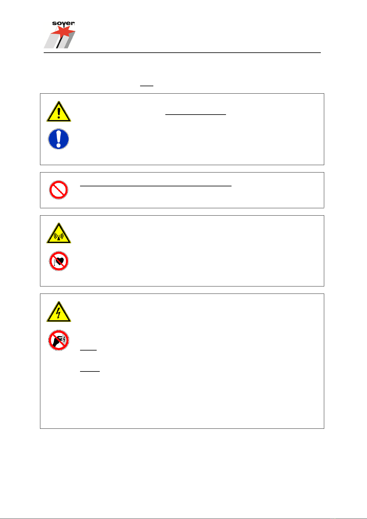
Warning of electromagnetic fields
Keep sufficient distance from electronic devices. When stud welding, highly intensive
electromagnetic fields are created which may permanently damage these devices (e.g.
television sets, airbags).
Ensure that the welding equipment is not operated near electronically sensitive life-
support equipment, such as in intensive care units in hospitals.
Persons with pacemakers may neither operate the stud welding equipment nor stay in
the immediate vicinity while it is running.
Electric shock can cause death
Prevent electric shock by insulating your body from the working area and the ground.
Stand on dry insulating material and wear rubber soled shoes.
Inspect all cables including power cord for damage, wear or bare wiring.
Always ensure the correct supply voltage in accordance with the type plate.
Never connect the welding equipment to a power supply network with incorrect supply
voltage.
Always disconnect the welding equipment from the mains supply before starting any
cleaning works. Only trained and appropriately qualified personnel are allowed to carry
out works at the electric mains supply and welding equipment.
Do not touch live electrical parts with bare hand. Wear dry, hole-free insulating gloves.
Do not wear rings, watches or electrically conductive jewellery.
Keep the work area, studs, guns, cables, energy source as well as your clothes dry.
9
Fumes and gases can cause damage to your health
Fumes and suspended/floating particles may be generated during welding. Beware of
fumes detrimental to health, particularly when using surface treated materials. Please
also observe the safety regulations applicable for your country.
Do not inhale fumes and gases. Use adequate ventilation in the work area to remove
fumes and gases.
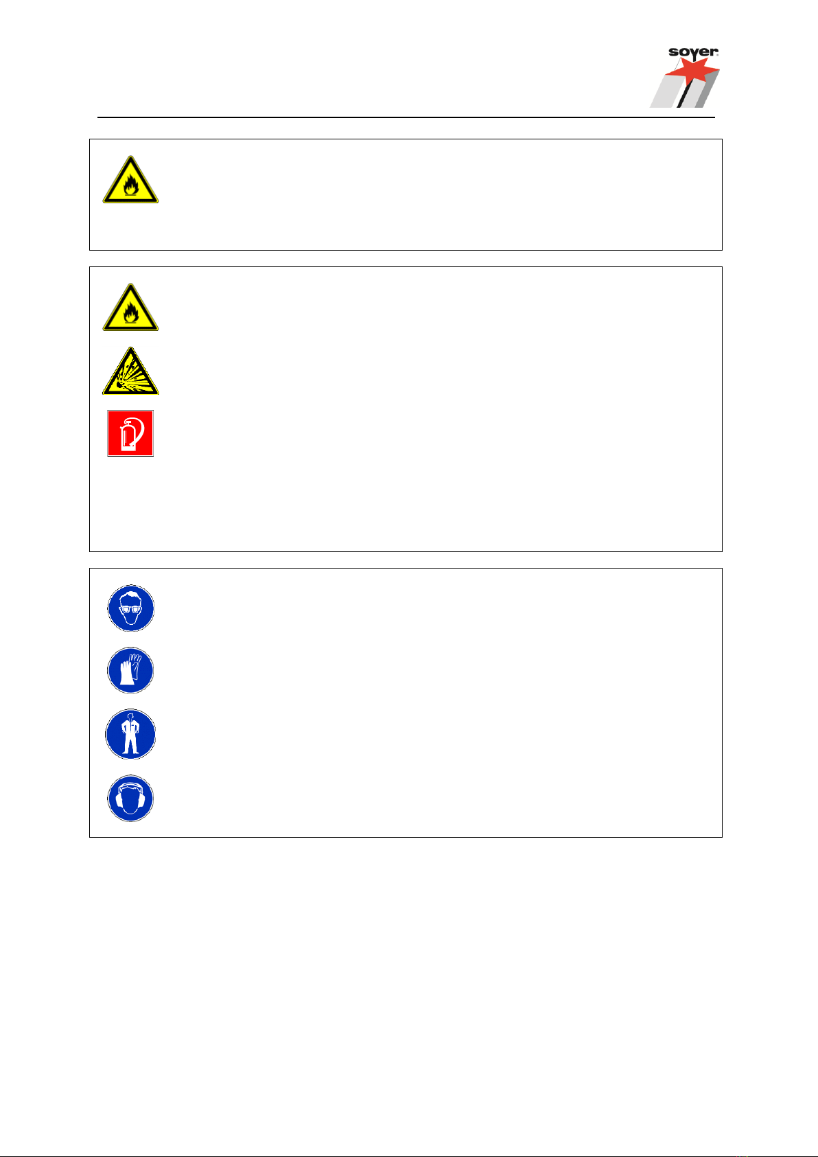
Welding can cause fire and explosions
Welding sparks and heat from flames and arcs can cause fires. Keep a portable fire
extinguisher within reach for immediate use. Be sure you are trained to use it.
When welding, do not wear clothes soiled with easily combustible substances such as
oil, grease and paraffin oil etc.
Comply with the fire regulations and do not weld, for instance, in hazardous locations.
Pay attention to flammable objects at the welding place. All flammable materials and
liquids, such as oil, fuel, etc. must be removed prior to the start of work.
Electronic equipment (e.g. airbags) and the use of explosive substances for fuel supply
require further safety precautions when carrying out welding operations on cars.
Appropriate information can be obtained from the trade associations or the car
manufacturers.
Skin and eye protection
Arc rays and welding spatters can injure eyes and skin.
Wear safety glasses with side shields and protective goggles with correct shade of filter
to protect your eyes from welding spatters and flashes of light that are generated during
the welding process.
Wear gauntlet gloves made of leather as well as non-combustible closed working
clothes such as heavy long-sleeve shirts, cuffless pants and safety shoes.
Wear a leather apron to protect your clothes from welding spatters.
Keep sleeves and collars buttoned and remove open pockets from the front side of your
clothing.
We recommend using ear protection. Some welding and working processes may
generate loud noises.

10
1.1 Description of reference signs in the operating instructions
The non-observance of safety instructions such as pictographs and warning words can cause damage
to persons. The safety instructions of this operating manual describe the following:
Safety instructions
Danger!
Warning!
Immediate hazards which could result in serious personal injuries or loss of
life.
Potential hazards which could result in serious personal injuries or loss of
life.
Caution!
Caution!
Potential hazards which could result in minor personal injuries.
Warning of damage.
Note!
Important!
Potential detrimental situation which may cause damage to the product or
to an object surrounding it.
Instructions for application and other useful information facilitating the
proper use of the product.
Safety symbols
The following pictographs for warnings, prohibitions and regulations are used in this manual:
Prohibited for persons
with pacemakers
Prohibited (only in
combination with an
additional safety symbol)
Do not touch
Housing is current-
carrying
Fire extinguisher
Warning of a danger
spot
Warning of dangerous
electric voltage
Warning of
electromagnetic field
Warning of moving
parts
General prohibition
(only in combination
with an additional
safety symbol)
Warning of inflammable
substances
Warning of explosive
substances
Eye protection required
Protective clothing
required
Ear protection
required
Protective gloves
required
General instructions are marked with the hand symbol.

11
1.2 Staff qualification and training
The staff responsible for operation, maintenance, inspection and assembly must have the respective
qualification for carrying out these works. Field of responsibility, competence and the supervision of
staff must be carefully regulated by the user. If your personnel do not have the necessary knowledge,
they must be trained and instructed. If necessary, this can be done by the manufacturer/supplier on
behalf of the user. Furthermore, the user must ensure that the contents of the operating instructions
have been fully understood by the staff.
The society of welding institutes (GSI: Gesellschaft der Schweißtechnischen Institute mbH) offers the
appropriate training courses for your personnel.
For information on branches, please refer to website http://www.dvs-ev.de.
1.3 Dangers in the case of non-compliance with safety instructions
The non-compliance with safety instructions may not only endanger persons, but also the equipment
and its environment. Any non-compliance with safety instructions may result in a complete loss of
damage claims.
The following dangers may result if the safety instructions are not complied with:
Failure of important system functions.
Failure of prescribed methods for maintenance.
Danger to persons through electrical, mechanical, thermal and/or acoustic influences.
1.4 Before starting to weld...
Check the state of all cables and cable connections before starting to weld.
Immediately replace defective cables and cable connections.
1.5 Working with the stud welding equipment
Comply with all accident prevention regulations applicable to the operation of your welding equipment.
If an accident happens,
switch off the welding equipment and disconnect it from the mains supply and
call a doctor.
1.6 Inadmissible operating methods
Limit values
The working safety of the stud welding equipment is only guaranteed when the system is used in
accordance with its purpose. The limit values indicated in the chapter “Technical data” must never be
exceeded.
1.7 Stopping the stud welding equipment
Turn off the mains switch of the stud welding equipment.
Disconnect the mains plug from the mains socket.
In case of automatic operation, disconnect the compressed-air supply.
Disconnect the earth cable from the welding equipment.
Disconnect welding gun or head from the welding equipment.
Roll up the cables without buckling them.
Prevent the welding equipment being operated by unauthorized personnel.
Check welding cables and connections of the welding equipment for damage such as burn-off,
mechanical wear etc. and have damaged parts replaced by the SOYER®customer service.

12
2 General
2.1 The following should be principally observed...
With the BMH-30i stud welder you have purchased a product which
is state-of-the-art technology
fully complies with the current safety requirements and
ensures high performance.
Before installing the welding equipment, please observe the following:
Store the operating instructions in a place accessible to every operator.
Ensure that the respective operator has read and understood the operating instructions prior
to start-up. Each operator should confirm this per signature.
Prevent the welding equipment being operated by unauthorized personnel.
Only trained personnel may operate the stud welding equipment.
2.2 Intended use
The BMH-30i DA stud welder allows you to weld SOYER®threaded studs from M8 –M24 or Ø 6 –25
mm (studs, shear connectors, concrete anchors) and manufactured from steel, stainless steel and
heat-resistant steel on different types of workpieces (sheets, tubes, steel girders etc.).
Usually round pins with or without thread are welded. You may, however, also weld fasteners with
different cross-sectional shapes. For this purpose special stud chucks and ceramic ferrules or gas
shrouds are required.
With the BMH-30i SOYER®stud welder it is also possible to weld studs of other metallic materials
than steel. It is, however, absolutely necessary to first carry out experimental welds and to inspect
them.
Manual electric welding (electrode welding) and TIG welding are also possible to a limited extent.
2.3 Marketing and service
If you have any questions regarding the operation of retrofits for special applications or if you require
service, please contact your responsible service office or the following address:
Heinz Soyer Bolzenschweißtechnik GmbH
Inninger Straße 14
D-82237 Wörthsee
Tel.: +49 8153 8850
Telefax: +49 8153 8030
www.soyer.de
2.4 Information on the documentation
The following operating instructions are supplied with the BMH-30i stud welder:
• Operating instructions for BMH-30i Order no.: P00234
13
2.4.1 Information on the operating instructions
Legal relationship
We point out that the contents of these operating instructions are neither part of any former or existing
arrangement, pledge or legal relationship nor have they been designed to modify the latter. All
obligations of Heinz Soyer Bolzenschweißtechnik GmbH result from the respective contract of
purchase. This contract also contains the complete and universally valid warranties. These contractual
warranty terms are neither extended nor restricted by the implementation of these operating
instructions.
CAUTION
Do not carry out any actions on the stud welding equipment without specifically knowing
the operating instructions or the respective part. Ensure that only qualified and trained
personnel familiar with the operating instructions operate the system.
2.4.2 Conduct in the case of malfunctions
If malfunctions occur, first try to detect and eliminate the causes according to the list in the
"Troubleshooting" chapter of these operating instructions. In all other cases, contact our service
department.
If you require our service, please make sure that you supply us with the following information:
Customer number
Product designation / options
Serial number
Year of construction
Material of stud and workpiece
Stud dimensions
This information helps us save time and unnecessary costs, e.g. incurred by delivering the wrong
spare parts.

14
3 Description of stud welding equipment
3.1 Description
The BMH-30i SOYER®stud welder is universally applicable for both manual and automatic operation
(optional). Control via a serial CNC interface is possible (option).
The BMH-30i stud welder enables the storage of parameters for various welding tasks as welding
programs. These parameters can be recalled at any time. To simplify operation, it is possible to store
programs for different stud diameters. This allows a more rapid and simpler interchange of different
welding tasks. The integrated quality control (option) allows the most important parameters of the weld
to be monitored and any welding faults to be reported when inadmissible deviations occur.
The stud welding equipment is equipped with four keys, eight light-emitting diodes (LED) and a two-
lined text display at the front panel. The stud welding equipment is adjusted via the keys. The
operating state during welding is shown by the light-emitting diodes and on the display.
The following welding methods are possible when using the BMH-30i SOYER®stud welder:
● Short-cycle drawn arc stud welding without shielding gas and ceramic ferrules
● Drawn arc stud welding using ceramic ferrules as auxiliary aid
● Drawn arc stud welding using shielding gas as auxiliary aid
● Manual electric welding (electrode welding)
● TIG welding
The PH-5L stud welding gun with control cable is the standard gun to be connected to the BMH-30i
stud welder. This operating manual exclusively describes the BMH-30i stud welder.
Information regarding the stud welding guns to be used as well as their setting can be obtained from
the respective operating manuals of the stud welding guns.
3.1.1 Drawn arc stud welding technology using shielding gas
With this method, a gas mixture containing 82% of Argon and 18% of CO2(e.g. Corgon®18*) is used as
auxiliary aid. This shielding gas protects the welding point from the atmosphere and simultaneously
supports the weld pool. Moreover, it ensures a concave fillet weld upset formation with a blank metallic
surface, thus reducing the risk of corrosion and obtaining an improved dynamic behaviour of the
welded joint.
An accurate bulging, to scale or in a calibrated or reproducible type is not possible when welding with
shielding gas without using any auxiliary aid. Stud welding with shielding gas can be carried out at
much shorter intervals as no ceramic ferrules have to be fitted and removed in each welding process.
*) Corgon®18 is a gas mixture of Linde AG in D-82049 Höllriegelskreuth
15
R
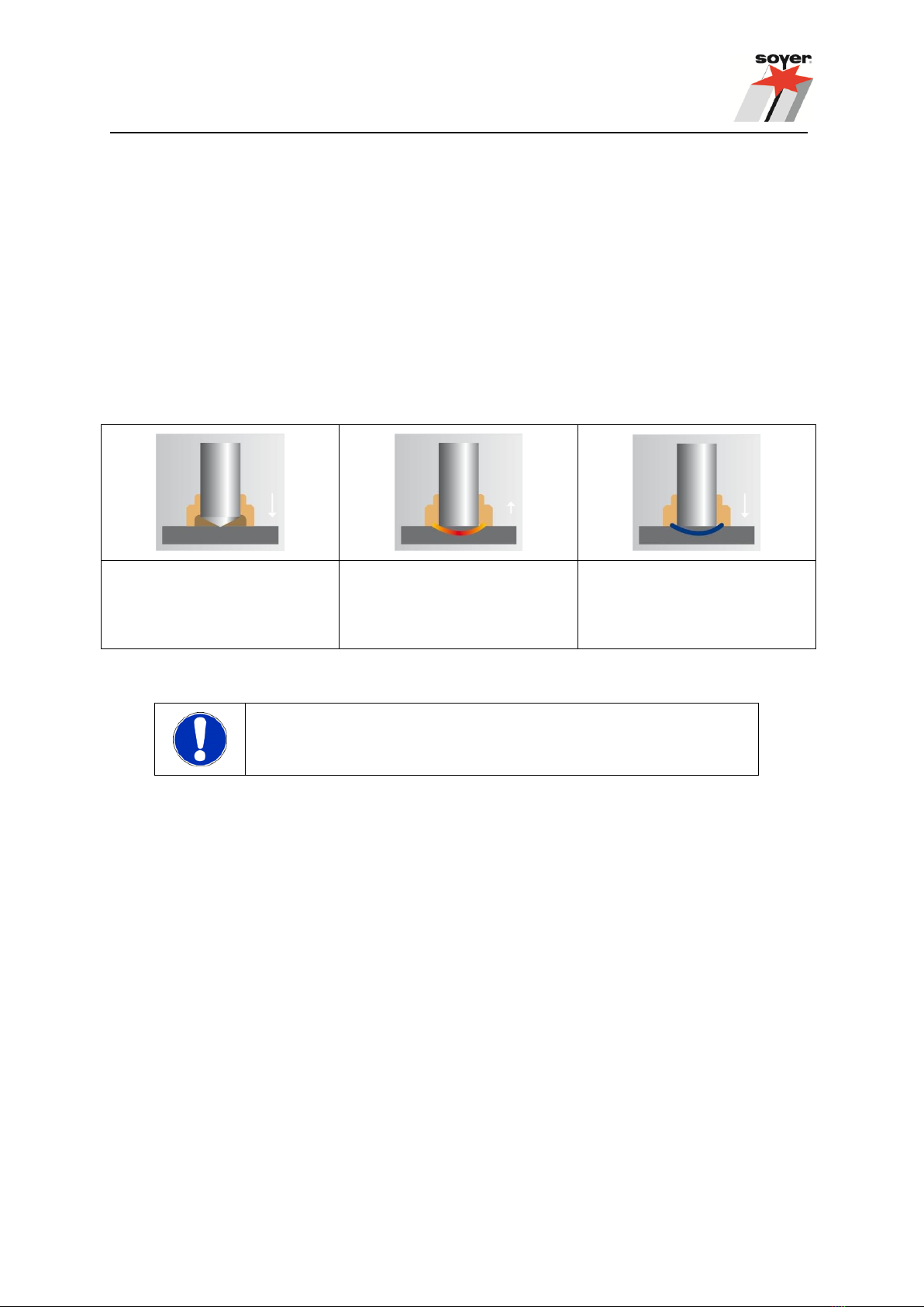
3.1.2 Drawn arc stud welding technology using ceramic ferrules
The ceramic ferrule fulfils the following functions:
• It centres the electric arc.
• It protects the welding point from the atmosphere.
• It ensures the exact formation of the welding bead.
• It prevents too rapid cooling of the weld pool.
• It partially protects against spraying sparks.
To ensure a perfect and accurate weld upset, each stud requires a ceramic ferrule matching its
diameter and shape. After every welding process, the ceramic ferrule must be knocked off and
replaced by a new one. Usually this method allows you to weld in any position.
The stud tip comes into contact
with the workpiece.
The stud lifts to a pre-set
height. The arc is ignited.
The stud is immersed in the
weld pool. The material
solidifies and the stud is
permanently welded.
IMPORTANT INFORMATION
Ensure ceramic ferrules are absolutely dry.

16
3.2 Technical data
Designation
BMH-30i
Welding process
Drawn arc stud welding (DA)
Electrode welding rectifier
Welding range
SOYER®threaded studs, DIN EN ISO 13918 from
M8 - M24 or Ø 6 - 25 mm
Material
Steel, stainless steel and heat-resistant steel (aluminium
conditionally depending on respective requirements)
Power source
Inverter technology
Welding current
360 up to 3000 A stud welding
120 up to 450 A electrode welding
120 up to 300 A TIG welding
Welding time
3 up to 2000 ms (only with operating mode "stud welding")
Welding sequence
Up to 30 studs/min with Ø 6 mm | up to 3 studs/min with Ø 25 mm
Standard gun
PH-5L stud welding gun
Power supply
CEE 125 A (3P + safety earth conductor)
3 x 400 V 50/60 Hz +10% -15%
E-continuous current
2 A / phase
E-continuous power
1400 VA
E-peak current
270 A / phase with 3 x 400 V (short-time operation)
Open-circuit voltage
85 V / DC (direct voltage)
System of protection
IP21
Interfaces (option)
Feeder interface: 15-pole socket (optional)
CNC interface : 9-pole socket(optional)
RS 232 interface: 9-pin plug (with SO-250 option)
Ext. program selection
PG.Select interface : 9-pole socket (optional)
Compressed-air supply
max. 7 bar (compressed air only with optional automatic set)
Shielding gas supply
max. 4 –5 l/min.
Dimensions
710 x 790 x 1030 mm (w x h x d)
Weight*
167 kg
Colour
RAL 5009 azure
Technical specifications are subject to change without notice.
* Slight deviations are possible depending on accessories.
WARNING
The "S" symbol is the symbol for welding current sources permitted for operation with
increased electrical danger. The "S" symbol on our stud welding devices refers
exclusively to the welding current circuit and not to the complete stud welding
equipment.
17
3.3 Interfaces BMH-30i
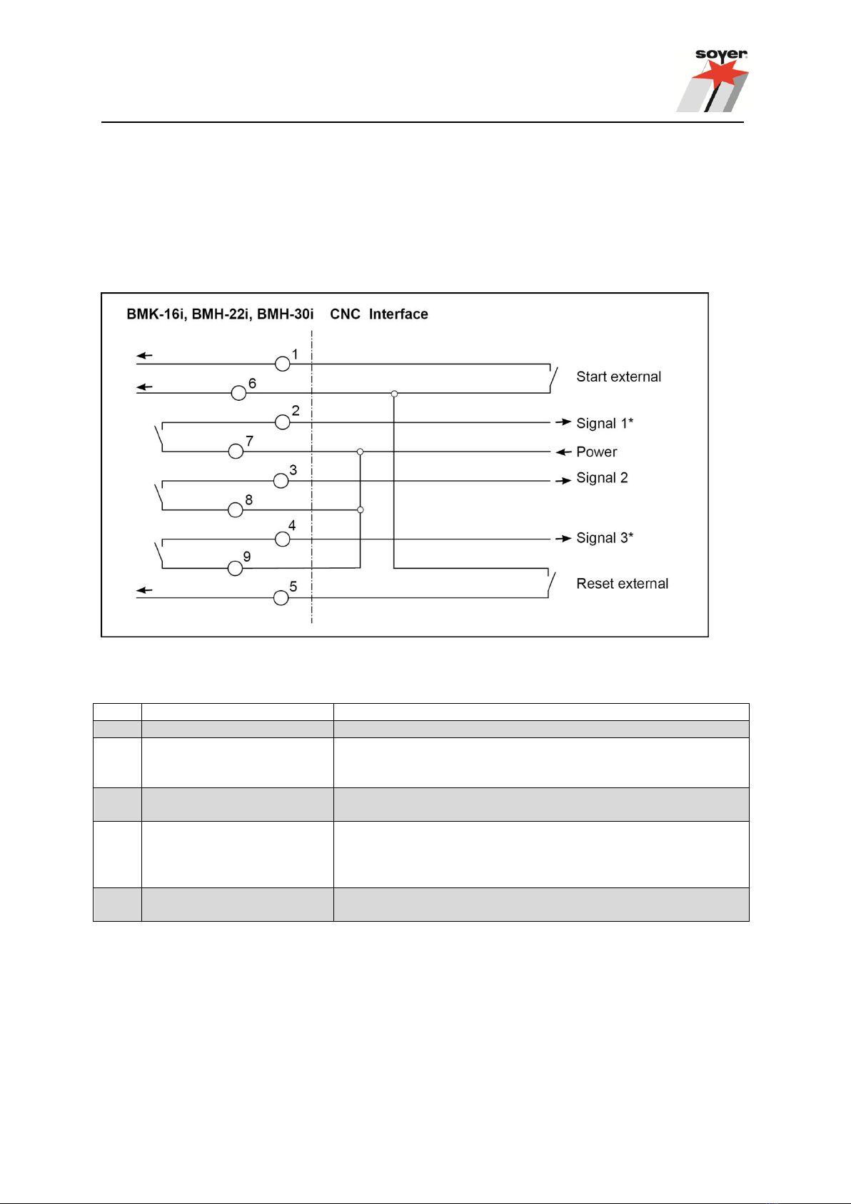
3.3.1 CNC interface
The CNC interface serves for the control and communication e.g. in conjunction with a CNC stud
welding machine.
Circuit diagram of CNC interface
Description of CNC interface
PIN
Identification
Description
1+6
Start external
Contact releases the welding process.
2+7
Signal 1 (QUAKO option)
Weld is OK: Contact is present during operation. It is
interrupted in case of a faulty weld and can be reset with
"Reset external".
3+8
Signal 2 (SOW)
Stud onto workpiece
Contact is made when stud touches the workpiece.
4+9
Signal 3 (QUAKO option)
Final contact:
Contact is reset after welding e.g. in order to prevent an
external control from being released/started.
6+5
Reset external
Error reset, external
Contact resets error messages.
3.3.2 RS 232-interface (SO-250 option)
The RS 232 interface serves as a "printer interface" or as "remote control" e.g. in conjunction with a
CNC stud welding machine.
A complete device configuration for the central control via a PC is possible via the interface. Operation
via the four function keys is therefore no longer necessary.
3.3.3 Feeder interface (optional)
The feeder interface serves as the control and communication of our systems for the external stud
feed e.g. by means of an UVR-300 SOYER®universal feeder.

18
3.3.4 PG.Select
Communication interface for the P3-Select/S gun distribution system. This interface serves for the
automatic selection of programs (for further information, please refer to the operating instructions of
the P3-Select gun distribution system).

19
4 Installation of welding equipment
The BMH-30i stud welding equipment is equipped with four lifting lugs on its top and can be easily
transported by means of four high-quality castors (two fixed castors and two guide castors with brake).
DANGER!
Please observe the following:
Serious personal injuries can be inflicted by falling equipment or add-on
units when lifting the welding equipment by crane!
Remove all accessory components (e.g. tool boxes, gas cylinder etc).
before lifting the welding equipment by crane
Disconnect the earth cables, the welding gun or head from the welding
equipment before lifting the welding equipment by crane
Disconnect the mains plug from the power supply
Transport the welding equipment on all lifting lugs at the same time
The lifting eyes must be completely screwed in
Check that the lifting eyes are securely fastened prior to use and
check for any damage such as corrosion and deformation
Do not use damaged lifting eyes
Avoid lateral loading of the lifting eyes
Ensure that there is an even load distribution! Only use ring chains or
suspension ropes of the same length
Avoid jerky movements when raising or lowering
Use load hooks of the appropriate size
Only install the stud welding equipment on an even surface.
Although the stud welding equipment is resistant to environmental influences, it should be
protected against dampness and dust.
Please pay particular attention to the bearing strength of the workshop furniture and ensure a
safe and stable position of the welding equipment.
Make sure there is sufficient free space around the air apertures, otherwise the device safety
mechanism will respond and interrupt the welding process. This state, represented as "Unit
not ready" is shown alternately with the current operating mode on the display.
Install the stud welding equipment close to the welding location.
Ensure correct connected loads for electrical connections:
Socket CEE 125A - 6h; 3 x 400 V~/ 50 Hz / 60Hz.
The BMH-30i stud welder has a four-core connecting cable: 3P + safety earth conductor.
Please observe that additional extension cables cause a voltage drop, possibly leading to
system disturbances.

20
When welding with shielding gas, make sure the gas cylinder is installed safely in its
approved, accident-proof installation device.
NOTE
The housing of BMH-30i stud welder corresponds to safety class IP21. Please
observe that this system of protection is not suitable for being operated or
transported in the rain.
This manual suits for next models
1
Table of contents
Other Soyer Welding System manuals


Soyer
Soyer BMS-4 ACCU-DUO User manual

Soyer
Soyer BMS-10P User manual

Soyer
Soyer BMS-9 ACCU User manual

Soyer
Soyer BMS-6 User manual

Soyer
Soyer BMK-10i User manual

Soyer
Soyer BMK-12 W User manual

Soyer
Soyer PH-9 SRM12 User manual

Soyer
Soyer BMK-16i User manual

Soyer
Soyer SRM EcoWeld BMK-20i User manual

Soyer
Soyer BMS-4 Akkumat User manual


