manuals.online logo
Brands
  1. Home
  2. •
  3. Brands
  4. •
  5. Speck
  6. •
  7. Water Pump
  8. •
  9. Speck P52/30-500MS User manual

Speck P52/30-500MS User manual

D1785 0618S
BETRIEBSANLEITUNG
OPERATING INSTRUCTIONS
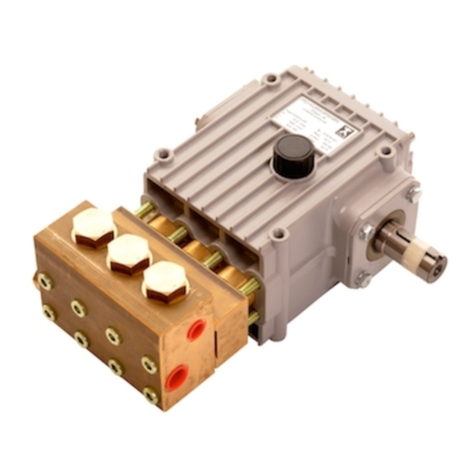
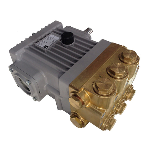
SPECK-TRIPLEX-PLUNGERPUMPE P52/30-500MS
SPECK TRIPLEX PLUNGER PUMP
Leistungsbereich - Performance
Type Best.-Nr. Leistungs-
aufnahme Überdruck
max.
Drehzahl
max.
Förder-
menge
max.
Wasser
temp.
max.
Plunger
-Ø Hub Gewicht
ca.
NPSHR
Code No.
Power
Consump. Pressure
max.
RPM
max.
Output
max.
Water-
Temp.
max.
Plunger
dia. Stroke
Weight
approx.
NPSH
Required
kW bar min-1 l/min °C mm mm kg mWs
P52/30-500MS
00.5973 29.5 500 1000 30.0 40 18 42 60.0 8.0
NPSH erf. ist gültig für Wasser (spez. Gewicht 1kg/dm
3) bei max. z
u-
lässiger Pumpendrehzahl.
Required NPSH refers to water: Specific weight 1kg/dm
3
, at max.
permissible pump revolutions.
Inbetriebnahme und Wartung
Operation and Maintenance
Vor Inbetriebnahme Ölstand prüfen und für störungsfreien Wasserzu-
lauf sorgen.
Check oil level prior to starting and ensure trouble-free water supply.
Bei Frostgefahr
muss das Wasser aus der Pumpe und den
angrenze
nden Anlagenteilen (insbesondere auch das UL-Ventil
) entleert
werden. Zum Entleeren kann der zweite, unbenutzte Druckanschluß ver-
wendet werden. Hierzu kann die Pumpe ca. 1
-2 Minuten „trocken“ laufen.
If there is a danger of frost
, the water in the pump and
in the pump fittings (particularly the unloader
valve) must be emptied.
The second discharge port can also be used and the pump run “dry” for
1
-2 minutes for this purpose.
Ölfüllmenge 3.0l. Nur Industriegetriebeöl ISO VG 220 (z.B. Aral Degol
BG220), oder
KFZ- Getriebeöl SAE 90 GL4 verwenden.
Erster Öl
wechsel nach 50 Betriebsstunden; dann alle 1000 Betrieb
s-
stunden, spätestens jedoch nach
1 Jahr. Achtung bei Betrieb in feuc
h-
ten Räumen bzw. bei hohen Temperaturschwankungen. Bei Kondens-
wasserbildung im Getrieberaum (Aufschäumen des Öles) sofort Öl-
wechsel d
urchführen.
NPSH
-Wert beachten. Max. Zulaufdruck 6 bar.
Darauf achten, dass
die Saugpulsation ausreichend gedämpft wird
–
Resonanz der starren
Wassersäule muss unbedingt vermieden werden.
Oil amount: 3,0 litres. Only use ISO VG 220 industrial gear oil (e.g.
Aral Degol BG220) or
automobile gear oil SAE 90 GL4.
Initial change after 50 operating hours and then every
10
00 operating
hours, after
1 year if used less.
Caution when operating in damp places or with high temperature
fluctuations. Oil must be changed
immediately should condensate
(frothy oil) occur in the gear box.
NPSH values must be observed.
Max. input pressure 6 bar.
Make
sure that suction pulsation is sufficiently dampened
–
water column
resonance must be avoided.
Sicherheitsvorschriften
Safety Rules
Es ist ein Sicherheitsventil gemäß den “Richtlinien für Flüssigkeitsstrah-
ler” vorzusehen, das so eingestellt ist, dass der B
e
triebsdruck um nicht
mehr als 10% übe
rschritten werden kann.
Bei Nichteinhaltung dieser Vorschrift sowie bei Überschrei
ten der Te
m-
peratur
- und Drehzahlgrenze erlischt jegliche Gewährleistung.
Beim Betrieb der Pumpe muss das freie Wellenende durch den Wel-
lenschutz (21), die angetriebene Wellenseite und Kupplung durch e
i
nen
bauseitigen Berührungsschutz abgedeckt sein.
Zur Mo
ntage des Wellenschutzes am freien Wellenende der Kurbelwe
l-
le
den Wellenschutz (21) zu
sammen mit dem Wellenschutzhalter (21A)
mit den Lagerdeckelschrauben (17) am Lagerdeckel (14) b
efestigen.
Vor Wartungsarbeiten an Pumpe und Anlage muß sichergestellt wer-
d
en, dass Druckleitung und Pumpe drucklos sind! Saugleitung ve
r-
schließen
.
Versehentliches Starten des Antriebsmotors durch geeignete Maß-
nahmen vermeiden (Sicherungen herausschrauben).
Vor Inbetriebnahme Pumpe und druckseitige Anlagenteile drucklos ent-
lüften
. Ansaugen und Fördern von Luft oder Luft-
Wassergemisch sowie
Kavitat
ion unbedingt vermeiden.
Kavitation bzw. Kompression von Gasen führt zu unkontrollierba-
ren Druckstössen und kann Pumpen
- und Anlagenteile zer
stören
sowie Bedienungspersonal gefäh
rden!
SPE
CK-TRIPLEX-
Pumpen sind geeignet zur Förderung von sauberem
Wasser oder anderen nicht aggressiven oder abrassiven Medien mit
ähnlichem spezifischen Gewicht wie Wasser.
Werden andere Flüssigkeiten, insbesond
e
re brennbare, explosive
und toxische M
edien geförd
ert, so ist eine Rücksprache mit dem
Pumpenhersteller hinsichtlich der Materialbeständigkeiten unbe-
dingt erforderlich. Die Einhaltung der entsprechenden Sicher-
heitsvorschriften ist durch den Gerätehersteller bzw. durch den
Anwender sicherzustellen.
A safety valve is to be installed in accordance with the guidelines for
liquid spraying units so that the admissible operating pressure cannot
be exceeded by more than 10%.
Pump operation without a safety valve as well as any excess in
temperature or speed limit
s automatically voids the warranty.
When the
pump is in operation, the
shaft end must be covered by shaft
protector (21) and the driven shaft side and coupling by a protective cover.
To cover the exposed crankshaft end, mount the shaft guard (21) to-
gether with the holder (21A) onto the bearing cover (14) and secure
with bearing cover screws (17).
Pressure in the discharge line and in the pump must be at zero before
any maintenance to the pump takes place. Close off suction line.
Take necessary precautions to ensure that the driving motor cannot get
switched on accidently (by disconnecting the fuses, for example).
Make sure that the pump and all parts on the pressure side of the unit
are vented and refilled, with pressure at zero, before starting the pump.
In
order to prevent air, or an air/water-
mixture being absorbed and to
prevent cavitation occurring, the pump positive suction head (npshr)
and water temperature must be respected.
Cavitation and/or compression of gases lead to uncontrollable
pressure
-kicks
which can ruin pump and unit parts and also be
dangerous to the operator or anyone standing nearby.
SPECK TRIPLEX Plunger Pumps are suitable for pumping clean water
and other non
-
aggressive or abrasive media with a specific weight
similar to water.
Before
pumping other liquids -
especially inflammable, explosive and
toxic media
-
the pump manufacturer must be consulted with regard
to the resistance of the pump material. It is the responsibility of the
equipment manufacture and/or operator to ensure that all
pertinent
safety regulations are adhered to.
SPECK - KOLBENPUMPENFABRIK
Otto Speck GmbH & Co. KG · Postfach 1240 · D-82523 Geretsried
Tel. (08171) 62930 · Telefax (08171) 629399
D1785 0618S
Instandsetzung Maintenance
Ventile überprüfen:
To Check Valves
Druckventile: Stopfen (50) herausschrauben. Bei darunter liegendem
Druckventil Federspannschale (44A) mit einer Flachzange, Ventilsitz
(44
D) ggf. mit Innenauszieher ø12 herausziehen.
Bei kpl. Ventil mit Schraubendreher durch Aussparungen in der Feder-
spannschale auf die Ventilplatte drücken und Ventil durch leichte He-
belbewegung zerlegen. Teile überprüfen, verschlissene Teile erse
tzen.
Stopfe
n (50) mit 145 Nm anziehen.
Discharge Valves: screw off tension plugs (50). Take the spring tension
cap (44A) out of the exposed discharge valve with a flat nose pliers.
Remove the valve seat (44D
). If necessary, use a dia. 12 pull-
out tool
to remove valv
e seat.
If the valve is extracted as a complete unit, position a screwdriver
through the recess in the spring tension cap and press down on the
valve plate to gently lever the valve apart.
Check parts and replace if worn. Tighten plugs (50) at 145 Nm.
Saugventile: 8x Muttern (47) lösen, Ventilgehäuse (45) von den Dich-
tungshülsen (35) abziehen. Dichtungskassette (42) mittels zweier
Schraubendreher aus dem Ventilgehäuse heraushebeln. Federspann-
schale (44A) mit einer Flachzange, Ventilsitz (44D) ggf.
mit Innenau
s-
zieher ø12 herausziehen.
Teile überprüfen, verschlissene Teile ersetzen.
Suction Valves: unscrew the 8 nuts (47) and remove the valve casing
(45) from seal sleeves (35). Using two screwdrivers, lever the seal case
(42) out of the valve casing. Remove
the spring tension cap with a flat
nose pliers. Remove the valve seat (44D). If necessary, use a dia. 12
pull
-out tool to remove valve seat.
Check parts, and replace if worn.
Die Leckagedichtung (39) muss mit der Bohrung Ø3 auf
den Knebelkerbstift (35A) in der Dichtungshülse (35) gesteckt werden.
Die Leckagerückfuhrbohrungen im Ventilgehäuse und in der
Dichtungshülse (35) müssen durch die Aussparungen in der Dichtung
(39) frei bleiben.
The leakage seal (39) with its Ø3 bores must be
positioned on to the notched pins (35A) situated on the seal sleeve.
Make sure the cut
-
outs in the leakage seal are placed exactly over the
bores of the seal sleeve (35) and that the drip return bores in the valve
casing are also free to thus ensure trouble
-free drip-return.
Muttern (47) zur Ventilgehäusebefestigung mit 80Nm gleichmäßig anziehen.
Tighten nuts (47) evenly at 80 Nm to secure the valve casing.
Dichtungen und Plungerrohr überprüfen:
To Check Seals and Plunger Pipe
8x Mutter (47) lösen, Ventilgehäuse nach vorne abziehen. Dichtungs-
hülse (35) aus den Führungen im Antriebsgehäuse herausziehen. Dich-
tungskassette (42) ggf. aus der Dichtungshülse (35) herausziehen.
Spannfeder (38A) und Dichtungseinheit (36
-38) aus der Dichtungshü
l-
se herausnehmen. Plungeroberfläche
n und Dichtungen (37) überpr
ü-
fen. Verschlissene Dic
htungen austauschen.
Leckagedichtung (33A) nach Entfernen des Seegerrings (32) und der
Stützscheibe (33) prüfen und ggf. austauschen.
Bei verschlissener Plungeroberfläche Plunger (29) herausschrauben (SW13),
Zentrierung und Stirnfläche des Kreuzko
pfes mit Plunger (25) säubern.
Neuen Plunger vorsichtig durch geölte Dichtungen in der Dichtungshül-
se fädeln. Gewinde des neuen Plungers dünn mit Schraubensiche-
rungsmittel (Loctite) bestreichen.
Dann Dichtungshülse
mit Plunger in die Führung des Antriebsgehäuses
schieben bis das Gewinde des Plungers (29) am Plunger (25) anstößt.
Unscrew the 8 x nut (47), remove valve casing by pulling it off to the
front. Take the seal sleeves (35) out of their guides in
the crankc
ase. If
necessary, remove the seal case (42) from the seal sleeve (35).
Remove tension spring (38A) and seal parts (36
-
38) from seal sleeve.
Check plunger surfaces and
seals (37). Replace worn parts.
After removing clipring (32) and support ring (33), check leakage seal
(33A) and replace if necessary.
If the surface of the plunger is worn, screw out the plunger (29) with a
size 13 tool. Clean the centring and front surface of crosshead with
plunger (25).
Thread new plunger carefully through oiled seals in seal sleeve. Coat
the thread of new plunger lightly with bonding agent (Loctite).
Then insert the seal sleeve together with the plunger into crankcase
guide
until the threads of the plunger (29) push against plunger (25).
Dichtungshülsen nicht vollständig in die Führungen
des
Antriebsgehäuses
drücken
bis die Plunger (29) verschraubt sind, da
ansonsten die Leckag
edichtung (33A) abgeschert wird.
Push the seal sleeves all the way into the
crankcase
guides only after
the plungers (29) have been screwed in,
as otherwise
the leakage seal (33A) will be shorn off.
Antrieb durchdrehen bis alle Plunger anstoßen und Plunger (29) mit
Drehmomentschlüssel (SW13) mit 30Nm anziehen.
Danach die Dichtungshülsen (35) vollständig in die Führungen des
Antriebsgehäuses drücken.
Crank the drive until all the plungers have been to the top; tighten
plungers (29) at 30 Nm using a size 13 torque wrench.
Then press the seal sleeves (35) all the way into the crankcase guides.
Die Leckagedichtung (39) muss mit der Bohrung Ø3 a
uf
den Knebelkerbstift (35A) in der Dichtungshülse (35) gesteckt werden.
Die Leckagerückfuhrbohrungen im Ventilgehäuse und in der Dich-
tungshülse (35) müssen durch die Aussp
a
rungen in der Dichtung (39)
frei bleiben.
The leakage seal (39) with its Ø3 bore
s must be
positioned on to the notched pins (35A) situated on the seal sleeve.
Make sure the cut
-
outs in the leakage seal are placed exactly over the
bores of the seal sleeve (35) and that the drip return bores in the valve
casing are also free to thus ens
ure trouble-free drip-return.
Muttern (47) zur Ventilgehäusebefestigung mit 80Nm gleichmäßig anziehen.
Tighten nuts (47) evenly at 80 Nm to secure the valve casing.
Getriebe zerlegen:
To Dismantle Gear
Nach Demontage von Ventilgehäuse und Plungerrohren Öl ablassen,
Getriebedeckel (4) und Lagerdeckel (14) abschra
uben.
Pleuelschrauben lösen und vordere Pleue
l
teile so weit wie möglich in
Kreuzkopfführung vorschieben.
After removing the valve casing and plunger pipes, drain the oil. Screw
off gear cover (
4) and bearing cover (14).
Take off conrod screws and push the front of the conrods as far as
possible into the crosshead guide.
Pleuel sind gekennzeichnet. Halbschalen nicht verdrehen.
Pleuel beim Zusammenbau wieder in gleicher Position auf die
Wellen
zapfen der Kurbelwelle montieren.
Connecting rods are marked for identification. Do not
twist conrod halves. The conrods must be remounted on to the shaft
journals in their exact original position.
Kurbelwelle unter leichtem Drehen mit Gummihammer nach einer Seite
herausklopfen.
Turning the crankshaft slightly, hit it out carefully using a rubber
hammer.
Pleuelschäfte nicht verbiegen. Anschließend Laufflächen
der Welle und der Pleuel, sowie Wellendichtringe und Kegelrollenlager
überpr
üfen.
Do not
bend the conrod shanks. Check shaft and
conrod mounting surfaces as well as the shaft seal rings and roller
bearings.
Zusammenbau:
Reassembling
Auf einer Lagerseite des Getriebes Lageraußenring mit weichem
Werkzeug einpressen bis dieser mit Außenkante der Lagerbohrung
bündig ist. Dann Lagerdeckel mit Wellendichtring und O
-Ring au
f-
schrauben. Welle durch gegenüberliegende Lagerbohrung einfädeln.
Lageraußenring einpre
s
sen und mit Lagerdeckel nach innen spannen.
Dabei Welle senkrecht halten und langsam durc
hdrehen, damit die K
e-
gelrollen der Lager am Bund des Lagera
u
ßenringes anliegen. Axiales
Lagerspiel min. 0.1mm max. 0.15mm durch Beilegen von Paßscheiben
(20A) unter einen Lagerdeckel einstellen.
Using a soft tool, press in the outer bearing ring on one side until the
outer edge lines up with the outer edge of the bearing bore. Screw on
the bearing cover together with the shaft seal and O
-
ring. Insert the
shaft through bearing bore on the opposite side. Press in outer bearing
ring and fix this with the bearing cover, keeping the shaft in a vertical
position and turning it slowly so that the taper rollers of the bearings
touch the edge of the outer bearing ring. Adjust axial bearing clearence
to at least 0.1mm and maximum 0.15mm by placing fitting discs (20A)
under the bearing cover.
Welle soll nach Montage ohne spürbares axiales Spiel
leicht drehbar sein. Anschließend Pleuelschrauben mit 3
0Nm anziehen.
After assembly has been completed, the shaft should
turn easily with very little clearance. Tighten c
onrod screws at 30Nm.

Other Speck Water Pump manuals

Speck P22/28-100 User manual

Speck

Speck P22/28-100 User manual

Speck BADUJET Perla Owner's manual

Speck

Speck BADUJET Perla Owner's manual

Speck P52 User manual

Speck

Speck P52 User manual

Speck NP25/30-280 User manual

Speck

Speck NP25/30-280 User manual

Speck P55/21-1000 User manual

Speck

Speck P55/21-1000 User manual

Speck P55/150-130 User manual

Speck

Speck P55/150-130 User manual

Speck P30/36-150RED User manual

Speck

Speck P30/36-150RED User manual

Speck NP10/10-140 User manual

Speck

Speck NP10/10-140 User manual

Speck BADU 93 Series Parts list manual

Speck

Speck BADU 93 Series Parts list manual

Speck NP25/15-500 User manual

Speck

Speck NP25/15-500 User manual

Speck NP25/70-120 User manual

Speck

Speck NP25/70-120 User manual

Speck Badu Stream II Operation manual

Speck

Speck Badu Stream II Operation manual

Speck P55/100-200 User manual

Speck

Speck P55/100-200 User manual

Speck P52/22-600 User manual

Speck

Speck P52/22-600 User manual

Speck BADUJET Perla User manual

Speck

Speck BADUJET Perla User manual

Speck P30 User manual

Speck

Speck P30 User manual

Speck NP25/70-100 User manual

Speck

Speck NP25/70-100 User manual

Speck 72 User manual

Speck

Speck 72 User manual

Speck NP30/90-150 User manual

Speck

Speck NP30/90-150 User manual

Speck NP25 User manual

Speck

Speck NP25 User manual

Speck P71/250-100RDK User manual

Speck

Speck P71/250-100RDK User manual

Speck Triplex NP25 Series User manual

Speck

Speck Triplex NP25 Series User manual

Speck P22/15-280 User manual

Speck

Speck P22/15-280 User manual

Speck Triplex P52/40-400MS User manual

Speck

Speck Triplex P52/40-400MS User manual

Popular Water Pump manuals by other brands

T.I.P. Clean Jet 1000 Plus operating instructions

T.I.P.

T.I.P. Clean Jet 1000 Plus operating instructions

SIP 04919 user manual

SIP

SIP 04919 user manual

GORMAN-RUPP SM SERIES Installation, operation and maintenance

GORMAN-RUPP

GORMAN-RUPP SM SERIES Installation, operation and maintenance

EBARA BSP SS Operating and maintenance manual

EBARA

EBARA BSP SS Operating and maintenance manual

Speck pumpen 2 VGX Series Installation and operation manual

Speck pumpen

Speck pumpen 2 VGX Series Installation and operation manual

Enerpac E-Pulse EP3204JB instruction sheet

Enerpac

Enerpac E-Pulse EP3204JB instruction sheet

ITT Goulds Pumps AF 42 LM Installation, operation and maintenance manual

ITT

ITT Goulds Pumps AF 42 LM Installation, operation and maintenance manual

JJM Boiler Works V Series Installation operation & maintenance

JJM Boiler Works

JJM Boiler Works V Series Installation operation & maintenance

Meec tools 020715 operating instructions

Meec tools

Meec tools 020715 operating instructions

Elmo Rietschle V-VC 40 OXY operating instructions

Elmo Rietschle

Elmo Rietschle V-VC 40 OXY operating instructions

DLS FlexxPump 500 user manual

DLS

DLS FlexxPump 500 user manual

DIVERSITECH CP-22 Installation and safety instructions

DIVERSITECH

DIVERSITECH CP-22 Installation and safety instructions

GORMAN-RUPP PUMPS 83C52-B Installation, operation, and maintenance manual with parts list

GORMAN-RUPP PUMPS

GORMAN-RUPP PUMPS 83C52-B Installation, operation, and maintenance manual with parts list

Conair RG Series user guide

Conair

Conair RG Series user guide

BUSCH COBRA AC 1000 F Installation and maintenance instructions

BUSCH

BUSCH COBRA AC 1000 F Installation and maintenance instructions

Clarke PW2 Operating & maintenance instructions

Clarke

Clarke PW2 Operating & maintenance instructions

Red Jacket Quick-Set UMP Series Replacement instructions

Red Jacket

Red Jacket Quick-Set UMP Series Replacement instructions

GORMAN-RUPP PUMPS 50 Series Installation, operation, and maintenance manual with parts list

GORMAN-RUPP PUMPS

GORMAN-RUPP PUMPS 50 Series Installation, operation, and maintenance manual with parts list

manuals.online logo
manuals.online logoBrands
  • About & Mission
  • Contact us
  • Privacy Policy
  • Terms and Conditions

Copyright 2025 Manuals.Online. All Rights Reserved.