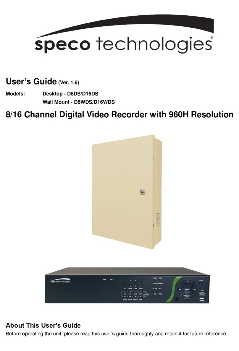
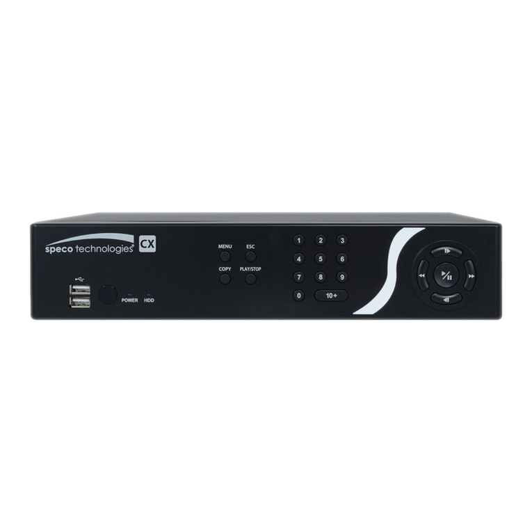
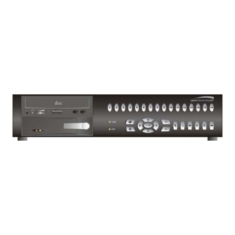
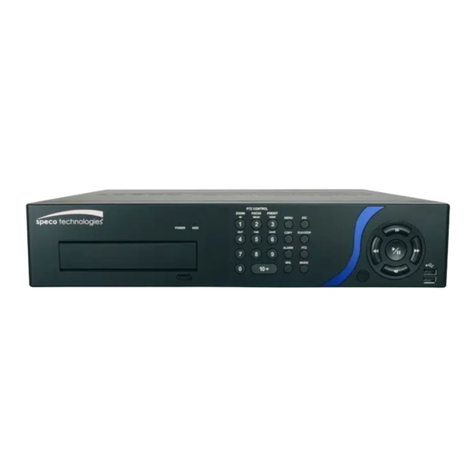
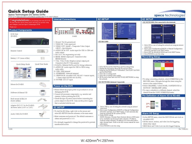
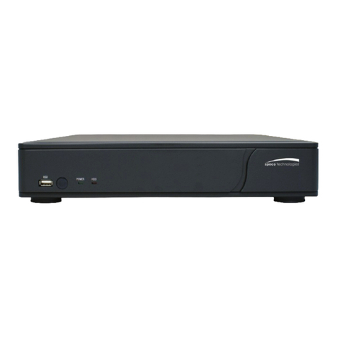
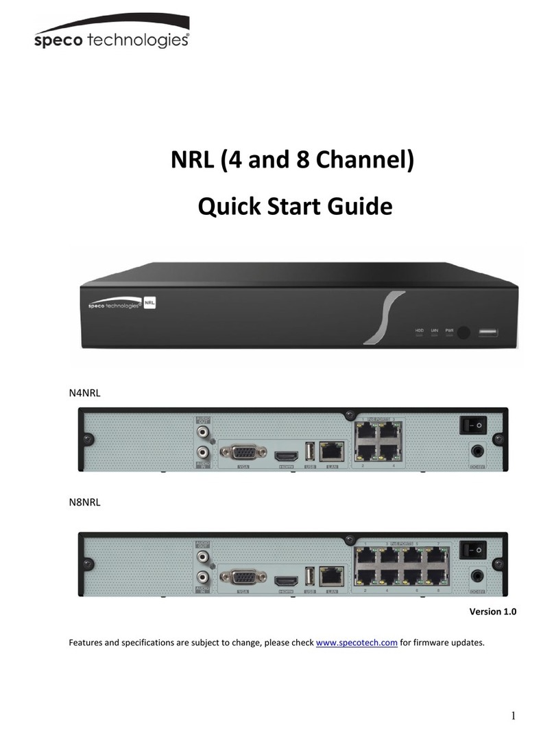
Speco CS4 Technical manual


Operation Instruction
2
Copy Button
Pressing the COPY button allows you to copy video clips.
Esc Button
During menu setup, pressing the ESC button closes the current menu or setup dialog box.
Play/Stop Button
Pressing the
PLAY/STOP button enters the playback mode, and pressing the button again exits the
playback mode. When entering the playback mode, video is paused. Pressing the (Play/Pause)
button plays back video at regular speed. he screen displays when the DVR is in the Pause
mode and the screen displays when the DVR is playing back video.
Camera Buttons
Pressing the individual camera buttons will cause the selected camera to display full screen. Buttons
1 to 9 are also used to enter passwords.
Arrow Buttons
hese buttons are used to navigate through menus and GUI. You can also use them to change
numbers by highlighting a number in the menu and using the
Up and
Down
arrow buttons to increase
or decrease the number’s value.
When in the PIP display format, pressing the
Up and Down arrow buttons moves the position of
the small screen counter-clockwise and clockwise, and pressing the
Left
and Right buttons changes
the PIP screen size.
In the playback mode, pressing the button plays video backward at high speed. Pressing the
button again toggles the playback speed from , and , and the screen displays ,
and respectively. While playing video, pressing the button plays video forward
at high speed. Pressing the button again toggles the playback speed from , and , and
the screen displays , and respectively. When in the pause mode, pressing the button
moves to the next image and pressing the button moves to the previous image.
Play/Pause Button
In the live monitoring mode, pressing the button freezes the current screen and the screen displays
icon. When in the playback mode, pressing the button pauses playing video.
Pressing the button selects a highlighted item or completes an entry that you have made during
system setup.
HDD LED
he DD LED flickers when the DVR is recording or searching video on the hard disk drive.

4- & 8-Channel Digital Video Recorder
3
Power LED
he POWER LED is lit when the unit is On.
USB Port
A USB port on the front panel is provided to connect external hard disk or flash drives for video
clip copying or system upgrades. Position external drives close enough to the DVR so that you
can make the cable connections, usually less than 6 feet. Use the USB cable provided with the
hard disk drive to connect it to the DVR.
A USB mouse (not supplied) can be connected to the USB port. You can use the mouse to navigate
through the screens and menus much like you would on a computer.
A USB to Serial converter can be connected to the USB port. Multiple text-in devices can be used
with a USB to Serial converter.
Remote Control Buttons
ID Button
Camera Buttons
Sequence Button
Login/Logout Button
Arrow Buttons
Menu Button
Playback Buttons
Alarm Button
Layout Button
Zoom Button
PTZ Button
Enter Button
Esc Button
PTZ Control Buttons
Copy Button
Play/Stop Button
Figure 4 ─ Infrared remote control.

Operation Instruction
4
ID Button
If a DVR System ID is set to 0, the infrared remote control will control that DVR without any
additional operations. (Refer to the System Information setup screen in this chapter for further
information on setting the System ID.) If the system ID is 1 to 16, you must to press the
ID button
and then press the number button (1 to 16 (+10 & 6)) in order to control that DVR. If the System
ID of two or more DVRs is set to 0, those DVRs will react to the infrared remote control at the
same time.
Camera Buttons
Pressing the individual camera buttons will cause the selected camera to display full screen. Buttons
1 to 9 are also used to enter passwords.
Sequence Button
When in the Live Monitoring mode, pressing the SEQUENCE button displays live channels
sequentially.
Login/Logout Button
Pressing the LOGIN/OUT button displays the Login or Logout screen.
Arrow Buttons
hese buttons are used to navigate through menus and GUI. You can also use them to change
numbers by highlighting a number in the menu and using the Up and Down arrow buttons to
increase or decrease the number’s value.
When in the PIP display format, pressing the
Up and Down arrow buttons moves the position of
the small screen counter-clockwise and clockwise.
Pressing the Left and Right buttons moves through screen pages in the Live Monitoring mode
and Search mode.
enu Button
In the Live Monitoring mode and Search mode, pressing the
MENU button displays the menu icons
at the top of the screen.
Playback Buttons
Rewind:
Pressing the button plays video backward at high speed. Pressing the button again
toggles the playback speed from , and .
Play/Pause: Pressing the button plays back video at regular speed. he screen displays
when the DVR is in the Pause mode and the screen displays when the DVR is playing back video.
Fast Forward:
Pressing the button plays video forward at high speed. Pressing the button
again toggles the playback speed from , and .

4- & 8-Channel Digital Video Recorder
5
Stop: Pressing the button stops playback and enters the Live Monitoring mode.
Backward: When in the pause mode, pressing the button moves to the previous image.
Forward: When in the pause mode, pressing the button moves to the next image.
In the Live Monitoring mode, pressing any playback button enters to the Search mode.
Alarm Button
Pressing the
ALARM button resets the DVR’s outputs including the internal buzzer during an alarm.
Layout Button
Pressing the LAYOUT button toggles between different display formats. he available formats
are: 3x3, 1P7, 1P5, 2x2 and PIP.
Zoom Button
Pressing the
ZOOM button zooms the current image on the screen. A PIP with a rectangle temporarily
displays showing what area of the screen has been enlarged. You can use the arrow buttons to
move the rectangle to another area.
PTZ Button
Pressing the
PTZ button enters the P Z (Pan/ ilt/Zoom) mode which allows you to control properly
configured cameras.
Enter Button
he (Enter) button selects a highlighted item or completes an entry that you have made during
system setup. his button is also used to enter the Cameo mode in the Live Monitoring mode or
Search mode (8-ch Model Only).
Esc Button
During menu setup, pressing the ESC button closes the current menu or setup dialog box.
PTZ Control Buttons
While in the P Z mode, the
PRESET buttons are used to save Presets and load a Preset View, the
ZOOM buttons are used to Zoom In and Zoom Out, and the FOCUS buttons are used for Near
Focus and Far Focus.
Copy Button
Pressing the COPY button allows you to copy video clips.

4- & 8-Channel Digital Video Recorder
6
Chapter 4 ─ Operation
NOTE: This chapter assumes your DVR has been installed and configured. If it has not,
please refer to Chapters 2 and 3.
he DVR’s controls are similar to a VCR. As with a VCR, the main functions are recording and
playing back video. However, you have much greater control over recording and playing back
video. You can establish recording schedules based on time of day and day of the week. he DVR
allows you to search through the recorded video using much more sophisticated tools than those
available with VCRs. Additional DVR features that are not available with VCRs are remote control
and viewing, and recording video at the same time you are watching previously recorded video.
he front panel controls are described in Chapter 3 ─ Configuration.
Turning on the Power
Once you have installed the DVR following the instructions in Chapter 2 ─ Installation, it is ready
to record.
Live onitoring
As soon as the DVR completes its initialization process, it will begin showing live video on the
attached monitor and playing live audio through the attached speaker. he default mode is to
display all cameras at once. Pressing any camera button will cause that camera to display full
screen. It displays live video and plays live audio until the user enters another mode.
While in the live monitoring mode, pressing the MENU button displays the following Live
Monitoring menu at the top of the screen. Pressing the ESC button hides the menu. You can
navigate through menus and items by pressing the arrow buttons.
Display
Freeze
Sequence
Camera Menu
Alarm
Digital Deterrent
Panic
Setup
Search Mode
Login/Logout
Figure 65 ─ Live Monitoring menu.

Operation Instruction
7
NOTE: The Live onitoring menu also can be displayed by moving the mouse pointer to
the top of the screen.
Live onitoring enu
Display
Selecting (Display Menu) in the Live Monitoring menu displays the following Display Menu.
Screen: Selecting Screen and choosing the screen mode (PIP, 2x2, 1P5, 1P7 or 3x3) displays
the cameras in the selected multiview screen mode. Selecting each display mode is the same
as scrolling the mouse wheel up and down when in one of the multiview formats (i.e., 2x2, 1P5,
1P7 or 3x3).
NOTE: In the 1P5 or 1P7 display mode, the main channel indicates the channel displayed
on the large screen which is displayed in the top-left. You can select the camera you want
to display on the main channel screen. Select a channel on the screen and click the right
mouse button to display the Camera enu. Selecting Go To Main swaps the selected
channel with the main channel. This function is supported only in the 1P5 and 1P7 display
modes and can be activated from any of channel screens except the main channel screen.
NOTE: You can change the location of the PIP (Picture-in-Picture)
counterclockwise or clockwise by pressing the Up and Down arrow buttons,
and change its size by pressing the Left and Right arrow buttons. To change
its location and size by using the mouse, select the PIP and then click the
right mouse button to display the following menu. Select the options you
want. You can also change the location of the PIP by clicking the left mouse
button on the PIP window and dragging it to where you want it located, and
change the size of the PIP by clicking the left mouse button at the corner of
the PIP window and dragging it until it is the desired size.
Previous Group, Next Group: Selecting Previous Group or Next Group moves to the
previous or next page.
Edit Group:
Selecting
Edit Group
enters the cameo mode. Refer to the following Active Cameo
Mode for details.
OSD: Selecting OSD toggles OSD On and Off.
Freeze
Selecting (Freeze) in the Live Monitoring menu will freeze the current image on the screen
until you select again. It is the same as pressing the (Play/Pause) button on the front panel.
While in the Freeze mode, the icon displays in bottom-left corner if Freeze is selected in the
Display setup screen (OSD tab).
Camera: Selecting Camera and choosing the camera number displays the
selected camera full screen. It is the same as pressing the individual camera
buttons on the front panel or clicking the left mouse button on a camera image
when in one of the multiview formats (i.e., 2x2, 1P5, 1P7 or 3x3). Clicking the
left mouse button on the screen again returns to the previous display mode.

4- & 8-Channel Digital Video Recorder
8
Sequence
Selecting (Sequence) in the Live Monitoring menu causes the cameras to display sequentially.
When in one of the multiview formats, selecting Sequence will cause the DVR to go through
predefined screen layouts (Full Sequence). Or, the bottom, right screen will display live cameras
sequentially (Cameo Sequence). For example, if you select (Sequence) in the Live Monitoring
in the 2x2 format, the 8-channel DVR changes pages as follows:
Full Sequence
Cameo Sequence
Selecting again in the Live Monitoring menu exits the Sequence mode. While in the Sequence
mode, the icon displays in bottom-left corner if Sequence is selected in the Display setup screen
(OSD tab). If all the cameras in a page are Off, or have lost video or are set to Covert (unless the
user has authority to view covert cameras), that page will be excluded from the sequence.
NOTE: The Full Sequence for the full sequence monitoring and the Cameo Sequence for
the cameo sequence monitoring should be selected in the Display setup screen ( ain
onitor tab).
Camera enu
Selecting (Camera Menu) in the Live Monitoring menu displays the following Camera Menu.
Zoom: Selecting
Zoom and choosing the camera number zooms the current image of the selected
camera on the screen. Refer to the following Zoom Mode section for details.
Audio: Selecting Audio toggles audio output On and Off.
Color Control:
Selecting
Color Control
and choosing the camera number allows you to control
brightness, contrast, hue and saturation for each camera for the selected camera if a user who
has Color Control
authority logs into the system. It is the same as pressing and holding a camera
button for a few seconds.
NOTE: It is important that cameras and monitors are correctly installed and adjusted prior
to making any image adjustments using the DVR’s controls.
NOTE: Any image adjustments you make will be applied to both the live video on the
monitors and the recorded video.
NOTE: The Camera Menu also can be displayed by clicking the right mouse button on the
screen while in the live monitoring mode.
Alarm
Selecting (Alarm) in the Live Monitoring menu resets the DVR’s outputs including the internal
buzzer during an alarm. It is the same as pressing any button on the front panel when the alarm
is activated.
PTZ: Selecting PTZ and choosing the camera number allows you to control
the selected camera as long as it has Pan, ilt and Zoom capabilities. Refer to
the following PTZ Mode section for details.

4- & 8-Channel Digital Video Recorder
9
Zoom ode
You can enlarge an area of the video by selecting (Camera Menu) Zoom in the Live
Monitoring menu. For a few seconds after selecting (Camera Menu)
Zoom from the Camera,
a rectangle displays on the screen. A rectangle shows the area that will be enlarged. You can move
the rectangle around using the arrow buttons. Pressing the (Play/Pause) button in the Zoom
mode enlarges the area in rectangle. Exit the Zoom mode by selecting (Exit) in the Zoom menu
displayed when pressing the
MENU button. While in the Zoom mode, the icon displays if
Zoom
is selected in the Display setup screen (OSD tab).
Event onitoring
When an event occurs, the DVR will display the camera associated with the event if Event
Monitoring On is selected in the Display setup screen (Main Monitor tab).
How the cameras are displayed depends on the number of cameras associated with the event. If
one camera is associated with the event, the DVR will display the camera full screen. If two to
four cameras are associated with the event, the DVR will display the cameras on a 2x2 screen. If
five to eight cameras are associated with the event, the DVR will display the cameras on a 1P5,
1P7 or 3x3 screen.
Event monitoring lasts for the dwell time set for event recording. After the dwell time has elapsed,
the monitor returns to the previous screen unless another event has occurred. If you want to return
to the live monitoring mode before the dwell time has elapsed, press one of the camera buttons.
Covert Camera
If a camera is set up as Covert 1 in the Camera setup screen (Settings tab), that camera will not
be displayed unless a user with Covert Camera View authority logs into the system. However
the camera title and status icons will be displayed on the monitor.
If a camera is set up as Covert 2 in the Camera setup screen (Settings tab), that camera appears
to be Off unless a user with Covert Camera View authority logs into the system. he camera
title will be grayed out and status icons will not be displayed on the monitor.
NOTE: When a camera is set up as Covert 1, the DVR displays the camera title and status
icons on the covert video. When set up as Covert 2, the DVR displays only the camera title
on the covert video.
If a user who has Covert Camera View authority logs into the system, the user can view video
from cameras set to Covert 1 or Covert 2 including the camera titles and status icons.
PTZ ode
If a user who has
PTZ Control authority logs into the system, the user can control P Z cameras.
he DVR will control cameras with Pan, ilt and Zoom capabilities. Select (Camera Menu)
PTZ in the Live Monitoring menu to display the P Z camera menu and enter the P Z mode.
Selecting (Exit) in the P Z menu displayed when pressing the MENU button exits the P Z
mode.
Operation Instruction
10
Camera Buttons:
Pressing the individual camera buttons will cause the selected camera to display
full screen.
Arrow Buttons:
Pressing the button plays video backward at high speed. Pressing the button
again toggles the playback speed from , and . Pressing the button plays video
forward at high speed. Pressing the button again toggles the playback speed from , and
. When in the pause mode, pressing the button moves to the next image and pressing the
button moves to the previous image.
Play/Pause Button: Pressing the button plays back images at regular speed or pauses playing
video.
Play/Stop Button: Pressing the PLAY/STOP button enters the playback mode, and pressing the
button again exits the playback mode. When entering the playback mode, video is paused. Pressing
the button plays back video at regular speed. he screen displays when the DVR is in the
Pause mode and the screen displays when the DVR is playing back video.
You can use a mouse for convenient playback control. Position the mouse pointer on the playback
screen, and the following Record able Search (Compact View Mode) screen will display. he
individual controls on the toolbar perform the following functions as described below:
Go to the previous image Play/Pause Go to the next image
Fast backward play Fast forward play
Searching Video
While in the search mode, pressing the MENU button displays the following Search menu at the
top of the screen. Pressing the ESC button hides the menu. You can navigate through menus
and items by pressing the arrow buttons.
Display
Search
Go To
Export
Camera Menu
Alarm
Digital Deterrent
Panic
Data Source
Exit
Figure 68 ─ Search menu.

4- & 8-Channel Digital Video Recorder
11
NOTE: The Search menu also can be displayed by moving the mouse pointer to the top
of the screen.
Search enu
Display
Selecting (Display Menu) in the Search menu displays the following Display Menu.
Screen:
Selecting
Screen and choosing the screen mode (PIP, 2x2 or 3x3) displays the cameras
in the selected multiview screen mode. Selecting each display mode is the same as scrolling
the mouse wheel up and down when in one of the multiview formats (i.e., 2x2 or 3x3).
Previous Group, Next Group: Selecting Previous Group or Next Group moves to the
previous or next page.
Edit Group: Selecting Edit Group enters the cameo mode.
OSD: Selecting OSD toggles OSD On and Off.
Search
Selecting (Search) in the Search menu displays the following Search menu.
See the following
E ent Log Search, Record Table Search, Motion Search and Text-In Search sections for details.
Event Log Search: Selecting Event Log Search selects video from the
event log.
Record Table Search: Selecting Record Table Search selects using a
recording table.
Motion Search: Selecting Motion Search selects motion events.
Text-In Search: Selecting Text-In Search selects text input strings.
Go To
Selecting (Go o) in the Search menu displays the following GO O menu.
Go to the First:
Selecting
Go to the First
displays the first recorded image.
Go to the Last:
Selecting
Go to the Last
displays the last recorded image.
Go to the Date/Time: Selecting Go to the Date/Time displays the Go
to the Date/ ime screen.
Move the cursor over the date and time and press the (Play/Pause)
button. You can use the Left and Right arrow buttons to highlight the
year, month, day, hours, minutes and seconds. Use the Up and Down
arrow buttons to change to the date and time you want to search for video.
Once you have set the date and time you want, press the button. hen highlight Go and press
the button. he selected date and time will display. (If no video was recorded during the selected
time, a message appears alerting you that no image was recorded at that time.) he button and
arrow buttons can now be used to review the surrounding video.
Camera: Selecting Camera and choosing the camera number displays the
selected camera full screen. It is the same as pressing the individual camera
buttons on the front panel or clicking the left mouse button on a camera image
when in one of the multiview formats (i.e., 2x2 or 3x3). Clicking the left mouse
button on the screen again returns to the previous display mode.

Operation Instruction
12
Export
Selecting (Export) in the Search menu displays the following Export menu.
See the following
Clip Copy section for details.
EZ Copy: Selecting EZ Copy will set the starting point of the video
to be clip copied, and the icon displays at the bottom-left corner of
the screen. Selecting EZ Copy again will set the ending point of the
video to be clip copied and displays the Clip-Copy screen.
Clip-Copy: Select Clip-Copy, and the Clip-Copy screen appears to allow clip copy setup.
Digital Deterrent Recording: Selecting Digital Deterrent Recording allows you to extract
audio files from recorded audio on the DVR. Refer to Chapter 3 – Configuration – Digital
Deterrent section for details.
Camera enu
Selecting (Camera Menu) in the Search menu displays the following Camera Menu.
Audio: Selecting Audio toggles audio playback On and Off. Recorded audio will be played
when the DVR displays a camera with recorded audio in full screen mode.
Enable De-Interlace: Selecting Enable De-Interlace turns the de-interlace filters on.
NOTE: The video signal has a time difference of 1/60 second (1/50 second for PAL) between
odd and even fields because it is composed of 60 interlaced fields per second (50 fields
for PAL). When recording video with Very High (D1) resolution, video is made up of frame
units combining two fields – one odd field and one even field. This can cause horizontal
scan lines or flashes in areas with motion because of the time difference between the
two fields. Turning on the de-interlace filter provides clearer video by eliminating these
horizontal scan lines and flashes.
NOTE: The Camera Menu also can be displayed by clicking the right mouse button on the
screen while in the search mode.
Alarm
Selecting (Alarm) in the Search menu resets the DVR’s outputs including the internal buzzer
during an alarm.
It is the same as pressing any button on the front panel when the alarm is activated.
Digital Deterrent
Selecting (Digital Deterrent) in the Search menu displays the following setup screen and allows
the DVR to play manually.
Highlight the box beside
Source name
and press the
button to select the source file to play. Highlighting
Trigger plays the selected file as the digital deterrent.
Zoom: Selecting
Zoom and choosing the camera number zooms the current
playback image of the selected camera on the screen.

13
Clip-Copy
Video clips can be copied on an external USB hard disk or flash drive. he copied video clips
can be viewed on computers running Microsoft Windows 98, ME, 2000, XP, Vista or 7. Refer
to the Appendix – USB Hard Disk Dri e Preparation for information on preparing the external
drive for clip copy.
Selecting
EZ Copy from the Export menu in the Search menu or pressing the
COPY button during
playback will set the starting point of the video to be clip copied, and the icon displays at the
bottom-left corner of the screen. Selecting EZ Copy again from the Export menu in the Search
menu or pressing the COPY button again will set the ending point of the video to be clip copied
by displaying the Clip-Copy screen.
Select Clip-Copy from the Export menu in the Search menu, press the
COPY button while in the
Search mode, and the Clip-Copy screen appears to allow clip copy setup.
Highlight the box beside
Channels and press the button. You can select the cameras that you
would like to include in your video clip.
Figure 73 ─ Clip-Copy screen.
You can search video from the first to last recorded
images, or you can set the start and stop times and dates.
Highlight the box beside From and press the (Play/
Pause) button to toggle between On and Off. When set
to Off, you can enter a specific Date and ime. When
set to On, the search will be from the first recorded image.
Highlight the box beside To and press the button to
toggle between On and Off. When set to Off, you can
enter a specific Date and ime. When set to On, the
search will be to the last recorded image.

Operation Instruction
14
Highlight the box beside
Password and press the button. A virtual keyboard appears allowing
you to enter the password for reviewing the video clips.
Highlight the box beside
Dest.
and press the button. You can select the storage device on which
you would like to record the video clip.
CAUTION: The USB device for clip copy must be FAT 16 or FAT32 format.
he DVR automatically assigns a file name to the video clip. However, you can give the video
clip file a different name. Highlight the box beside
File Name and press the button. A virtual
keyboard appears. Enter a file name for the video you are backing up and select
Close. he DVR
will automatically add the camera number (for example “01”) and “.exe” to the file name.
NOTE: When naming a file, you cannot use the following characters: \, /, :, *, ?, “, <, >, |.
Highlight Include Text-In Data and press the button. his will toggle between On and Off.
When this feature is On, you can include text-in data when copying video if the video was recorded
with text-in data.
Once you have given the video clip a file name, highlight the
Start button and press the button.
he confirmation screen displaying data size will appear. When the storage device does not have
enough space, the DVR will ask if you want to copy as much of the video clip as possible in the
available space.
Highlight the Continue button and press the button to continue clip copy.
Once the clip copy starts, you can cancel it by selecting Cancel or hide the screen by selecting
Close. When selecting
Close, Clip Copy continues and a confirmation screen will display when
complete.
NOTE: The file size for clip copy is limited to 30GB. When copying video clips larger than
2GB, the video clips will be save in units of 2GB. For example, 3 individual 2GB files will
be created when saving a 6GB video clip.
You can use other functions on the DVR while video is being backed up. o do this, highlight
the Close button and press the button. You can return to the
Clip-Copy screen at any time to
check the progress.
You do not need to install any special software on your personal computer to review the video
clips. Refer to the Speco Central Operation Instruction for instructions on how to review video
clips you have copied.
NOTE: During Clip Copy, you cannot shut the system down, clear data on the storage
device, or format the storage device.
CAUTION: Do NOT disconnect the USB cable or the power from the external drive while
copying video clips. If the external drive is shut down or the USB cable is disconnected
while copying video clips, THE DVR SYSTE AY NOT WORK NOR ALLY OR THE
EXTERNAL DRIVE COULD BE DA AGED, and you will get an error message the next
time you try to copy video clips. You will need to power down the DVR and restart it
to get rid of the error message. Once the file system of the USB hard disk drive has
been corrupted, this error message cannot be dismissed. Even after restarting the DVR
it may automatically restart while preparing to clip copy. You must recover the file
system using the recovery program, or you must reformat the hard disk drive.

Operation Instruction
15
Computer system requirements for using the Speco Remote program are:
Operating System: Microsoft ® Windows® XP x86 (32 Bit) (Service Pack 3), Microsoft®
Windows® Vista x86 (32 Bit) (Service Pack 1), Microsoft® Windows® 7 x86 (32 Bit)
CPU: Intel Pentium III (Celeron) 600MHz or faster
RAM: 128MB or higher
VGA: 8MB or higher (1024x768, 24bpp or higher)
Internet Explorer: Version 6.0 or later
Start Internet Explorer on your local PC. You can run the Speco Remote program by entering
the following information in the address field.
– “http://IP address:12088” ( he DVR IP address and the Speco Remote port number
(default: 12088) set in the Network setup screen (Speco Remote tab))
– Or, “http://DDNS.SPECO ECH.NE /YOURNAME” ( he DVRNS server address and the DVR name
registered on the DVRNS server)
NOTE: You will need to get the appropriate IP address for the DVR you want to connect
to and the Speco Remote port number from your network administrator.
NOTE: Speco Remote only works with icrosoft Internet Explorer and will NOT
Work with other browsers such as Google Chrome, ozilla, Firefox, etc..
Select between the Remote Watch (Web monitoring)
and Remote Search (Web search) modes. Entering
ID and PASSWORD and clicking the [
LOGIN] button
logs in using the selected mode.
NOTE: Do NOT close the LOGIN window during the Speco Remote operation, otherwise,
it will cause a script error when switching between Web monitoring and Web search modes
and running the Speco Remote program again will be required.
NOTE: When running the updated Speco Remote for the first time, Internet Explorer might
occasionally load the information of the previous version. In this case, delete the temporary
internet files by selecting Tools Internet Options General tab, and then run Speco
Remote again.
NOTE: There might be a problem that the bottom of Speco Remote page is cropped due
to the address or status bars in icrosoft Internet Explorer 7.0. In this situation, it is
recommended that websites open windows without address or status bars by changing
the internet setting. (Go to the Tools
Internet Options
Security tab
Click the Custom
level… button Select Enable for the Allow websites to open windows without address
or status bars option)
NOTE: When running Speco Remote in the icrosoft Windows Vista or higher operating
system, it is recommended to start Internet Explorer with elevated administrator permissions.
Click the right mouse button on the Internet Explorer icon and select the Run as administrator
option from the context menu. Otherwise, some functions of Speco Remote might be limited.

4- & 8-Channel Digital Video Recorder
16
NOTE: There might be a problem with screen display or screen update due to low image
transmission speed when using the icrosoft Windows Vista or higher operating system.
In this situation, it is recommended you disable the Auto Tuning capability of your computer.
Run the Command Prompt with elevated administrator permissions (Go to the Start enu
Accessories
Command rompt
Click the right mouse button and select the Run
as administrator option). Then enter “netsh int tcp set global autotuninglevel=disable”
and hit the enter key. Restart your computer to apply the changes.
If you want to enable the Auto Tuning capability again, enter “netsh int tcp set global
autotuninglevel=normal” after running the Command Prompt with elevated administrator
permissions. Restart your computer to apply the changes.
Web onitoring ode
Remote Watch is a remote web monitoring program that allows you to monitor live video
transmitted in real-time from the remote DVR.
① Click the to log out the Speco Remote program.
② Click the to access to the web search mode.
③ Position the mouse pointer on the WebWatch logo to see the version of the Speco Remote
program.
④ he DVR information window displays the login information of Speco Remote.
⑤ Click the screen format to select the desired display mode. When changing the screen format,
the selected camera on the current screen will be located in the first cell of the new layout.
⑥ Click the camera button to select the camera to be viewed.
⑦ Click the to adjust the brightness, contrast, saturation and hue of monitoring image.
⑧ Click the to control pan, tilt and zoom of the camera from a remote site.

Operation Instruction
17
⑨ Click the to control alarm out devices at the remote site.
⑩ Click the to set up the image drawing mode and OSD display. You can adjust the display
speed by changing the image drawing mode, and select OSD information to be displayed on
the screen.
⑪ Click the to save the current image as a bitmap or JPEG file format.
⑫ he event status window at the bottom displays a list of events that were detected from the
remote site.
⑬ Selecting a camera on the screen and clicking the right mouse button displays the text menu
screen.
Change Camera Title: Changes the camera name.
Enable Audio: Enables audio communication with the remote site. When the
audio control panel displays, click the to send audio to the connected remote
site and click the button again to stop sending audio. Click the to monitor live
audio from the connected remote site through the attached speaker and click the
button again stop
monitoring live audio. Clicking both and allows two-way
communication. Clicking the disables audio communication.
Aspect Ratio: Changes the image aspect ratio.
Deinterlacing
: Using a deinterlace filter for interlaced video enhances image display quality by eliminating
horizontal scan lines and noise in areas with motion.
Anti-Aliasing Screen: Enhances image display quality by eliminating stair stepping (aliasing) effects
in the enlarged image.
NOTE: A camera name change in the Remote Watch mode does not affect the camera name
set up on the remote site. Leaving the Camera Title blank causes the camera name set up
on the remote site to display.
NOTE: The icon will display on each camera screen when audio communication is
available between the Speco Remote system and a DVR.
Web Search ode
Remote Search is a remote web search program that allows you to search recorded video on the
remote DVR.
NOTE: The remote site connection in the Remote Search mode will automatically be
disconnected if there is no activity for 30 minutes.

4- & 8-Channel Digital Video Recorder
18
① Click the to log out the Speco Remote program.
② Click the to access to the web monitoring mode.
③ Position the mouse pointer on the WebSearch logo to see the version of the Speco Remote
program.
④ he DVR information window displays the time information of recorded data on the remote
DVR and login information of Speco Remote.
⑤ Click the to blur, sharpen, equalize and interpolate playback images. Click
the to zoom out or zoom in the recorded image. Click the to adjust
the brightness of the recorded images.
NOTE: Image processing works only in the pause mode.
⑥ he playback function buttons include fast backward, pause, play, fast forward, go to the first
image, go to the previous image, go to the next image, and got to the last image.
⑦ Click the screen format to select the desired display mode.
⑧ Click the to enter the time-lapse search mode which allows you to search
for recorded data by time and then play back images found within the time
parameters. he imetable window located at the bottom displays the time
information for the image of the date selected on the calendar. If more than
one video stream in the same time range, you can select the video stream you
want to search. Clicking a specific time displays the image recorded at that time on the screen.
Selecting the allows you to display an image from a specific time.
⑨ Click the to enter the event search mode which allows you to search for event log entries
using specific conditions and play back the images associated with those event entries.
⑩ Click the to set up the image drawing mode and OSD display. You can change the display
speed by adjusting the image drawing mode, and select OSD information to display on the screen.

Operation Instruction
19
⑪ Click the to save any video clip of recorded data as an executable file, or click the
to save
the current image in a bitmap or JPEG file format. Click the to print the current image on
a printer connected to your computer.
⑫ Click the to reload the recording data.
⑬ he timetable displays recorded data of the selected camera by time (in hour segments).
⑭ Selecting a camera on the screen and clicking the right mouse button displays the text menu
screen.
Change Camera Title: Changes the camera name.
Enable Audio
: Plays audio while playing back recorded video that has recorded
audio. (Single-Screen Layout Only)
Aspect Ratio: Changes the image aspect ratio.
Deinterlacing: Using a deinterlace filter for interlaced video enhances image
display quality by eliminating horizontal scan lines and noise in areas with motion.
Anti-Aliasing Screen: Enhances image display quality by eliminating stair
stepping (aliasing) effects in the enlarged image.
NOTE: A camera name change in the Remote Search mode does not affect the camera name
set up on the remote site. Leaving the Camera Title blank causes the camera name set up
on the remote site to display.
System Log Notices
Boot Up Schedule Off
Shutdown Panic On
Restart Panic Off
Upgrade Clear All Data
Upgrade Fail Format Disk
ime Change Disk Full
ime Zone Change Disk Config Change
ime Sync Disk ‘No.’ : ‘serial number’
ime Sync Fail Disk ‘No.’ : Removed
Disk Bad Auto Deletion
Login Search Begin
Logout Search End
Setup Begin Clip-Copy Begin
Setup End Clip-Copy End
Remote Setup Change Clip-Copy Cancel
Remote Setup Fail Clip-Copy Fail
Setup Imported Callback Fail
Setup Import Failure Import Digital Deterrent file complete
Setup Exported Import Digital Deterrent file error
Setup Export Failure Export Digital Deterrent file complete
Setup Export Cancel Export Digital Deterrent file error
Schedule On
Other manuals for CS4
1
This manual suits for next models
1
Table of contents
Other Speco DVR manuals

Speco
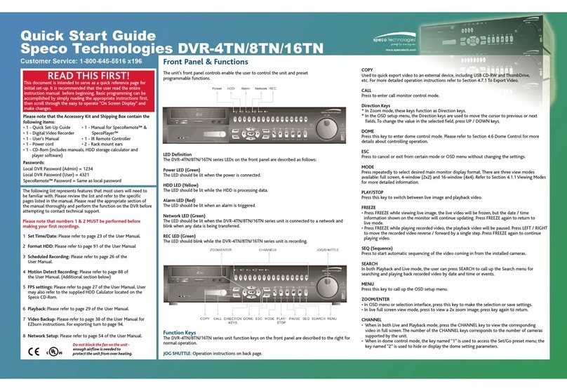
Speco DVR-16/IP User manual

Speco
Speco DVR-DS4TN User manual

Speco
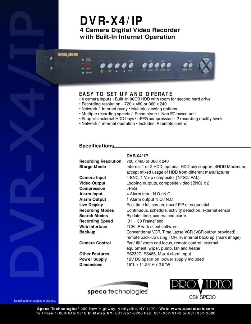
Speco DVR-X4/IP User manual

Speco
Speco DVR16TS750 User manual

Speco
Speco D4CS User manual

Speco
Speco DVR-4CF User manual

Speco
Speco HRLN User manual

Speco
Speco DVR-4TH Series User manual

Speco
Speco D8HS2TB User manual

Speco
Speco D4VN User manual