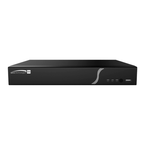
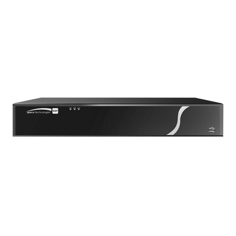
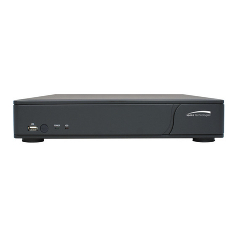
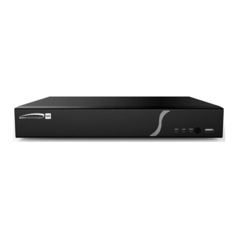
Speco DVR82HD User manual

User Guide(Ver.1.7)
Model: DVR82HD
2 Channel HDcctv + 8 Channel Full D1 Digital Video Recorder
About This User’s Guide
Before operating the unit, please read this user‟s guide thoroughly and retain it for future reference.

2
Cautions
Explanation of Graphical Symbols
WARNING
To reduce a risk of fire or electric shock, do not expose this product to rain or moisture.
CAUTION
Changes or modifications not approved by the manufacture will void the warranty of the product.
Using an incompatible battery may increase the risk of fire or explosion.
Replace only with the same or equivalent type battery recommended by the manufacture.
Discard used batteries according to manufacturer‟s instructions.
This symbol indicates the presence of important operating and maintenance
(servicing) instructions in the literature accompanying the product.
This symbol indicates the presence of “dangerous voltage” within the product’s
enclosure that may be of sufficient magnitude to constitute a risk of electric
shock, property damage, personal injury, or death.

3
These precautions must be followed for safety reasons.
Warning
Do not use if the unit emits smoke.
Do not disassemble the unit.
Do not place any heavy or sharp objects on the unit.
Do not place on uneven surface.
Do not expose to shock or vibration.
Do not move the unit when the unit is powered on.
Do not block, and allow dust to accumulate in the air vents.
Do not restrict airflow of the unit; doing so can damage the unit.
Installation and servicing should be performed only by qualified and
experienced personnel.
Turn off the power of the DVR when connecting Cameras, Audio or Sensor
Cables.
The manufacture is not responsible for any damage caused by improper use
of the product or failure to follow instructions for the product.
The manufacture is not responsible for any problems caused by or resulting
from the user physically opening the DVR for examination or attempting to
repair the unit.
The manufacture may not be held liable for any issues with the unit if the
warranty seal is removed.

4
Product Components
Please make sure the following components are included as specified below.
DVR Unit
Client Software CD
Remote Control
Battery1.5V (AAA x 2EA)
User‟s Guide
HDD SATA Cable (4 EA)
HDD Mounting Brackets (2 EA)
HDD Mounting Screws (16 EA)
HDD Mounting Rubber Ring (16 EA)
Power Cable (110V or 220V)
Mouse

5
Hard Drive Installation
1. Remove the screws and the top cover as specified below.
2. Fix the supplied HDD mounting bracket to the hard disk using the supplied mounting bracket screws.

6
3. Insert the HDD bracket to the hole and fix the screw.
4. Connect the supplied SATA cable and power cable to the hard disk.
NOTE) HDD2 SATA port is the main HDD port. When installing more than 2 HDDs, connect
HDD SATA cables in sequential order from HDD2.
NOTE) Please mount all HDDs which you want to use when installing at the first time. It does not allow
a movement, removal or supplement of HDD to the system which be in use.

7
Storage Estimation
Recording Condition
- Channel and Frame: 10 Channels (Full-HD@15fps or HD@30fps and D1@30/25fps)
- Recording by: Continuous
- Audio Recording: 10 Channel Audio On
HDD
LEVEL 5(H)
LEVEL 4
LEVEL 3
LEVEL 2
LEVEL 1(L)
day(s)
hour(s)
day(s)
hour(s)
day(s)
hour(s)
day(s)
hour(s)
day(s)
hour(s)
250GB
0
15
0
19
1
2
1
7
1
14
320GB
0
20
1
1
1
10
1
16
2
2
500GB
1
9
1
17
2
6
2
17
3
8
1TB
2
19
3
12
4
15
5
12
6
20
1.5TB
4
6
5
7
7
0
8
8
10
8
2TB
5
16
7
2
9
9
11
4
13
20

8
Specifications
Model
DVR82HD
Video
Input
Channel Input Level
2 CH HDcctv 720p / 1080p
8 CH Composite
Video Loss Check
YES
Output
Main Monitor Output
1 HDMI (Max. 1920x1080p60 and Various Resolution)
Sub Monitor Output
1 VGA (Max. 1920x1080p60 and Various Resolution)
CVBS and Spot
1 CVBS , 4 SPOT OUT
Audio
Input and Output
10 CH Input & 1 CH Output
Audio Codec
G.711
Alarm
Sensor Input
10 TTL, NC/NO Selectable
Alarm Out
4 Relay Out by Sensor, Motion and Video Loss
Record
Compression
H.264 (Main Profile)
Multi Operation
Quadplex (Playback, Recording, Backup, Network)
Resolution
HDcctv: 1920*1080, 1920*540, 1280*720, 640*360
Composite: 704x480, 704x240, 352x240
Recording Quality Grade
4 Levels
Recording Mode
Continuous, Schedule, Motion, Sensor, Manual
Motion Detection
Setup by Grid
Pre Recording
15 Seconds to 20 Minutes
Post Recording
10 Seconds to 60 Seconds
Playback
Multi Decoding
1, 4, 8, 10
Playback
Speed
Single Channel FF/FR
x0.25, x0.5, x2, x4, x8, x16, x32
Multi Channel FF/FR
x0.25, x0.5, x2, x4, x8, x16, x32
Search Mode
Timeline, Event, Archive, Log, Specific Time
Storage
HDD
Interface
Serial ATA
Capacity of 1 HDD
2TB
Internal HDD Number
4 EA
External Storage
1 eSATA
File System
NaFS2
Backup
Backup Format
JPEG, Video
Media
USB Flash Drive, USB External HDD, Network
User
Interface
Menu Display
GUI (Graphic User Interface)
Input Method
IR Remote Control, Mouse, Front Buttons
Serial Port
Console
1 RS-232C (D-sub 9pin)
PTZ & Keyboard Control
2 RS-485
Network
Dynamic DNS
Free DDNS
Streaming
RTP, RTSP

9
Network Interface
10/100/1000 Base TX Ethernet (RJ45 1EA)
Dual Network Streaming
2 CH HDcctv: H.264 640*360@120fps / 1280*720@120fps
8 CH Composite: CIF@240fps / D1@240fps
Network
Access
Web viewer (1:1)
Live, Search, Backup, PTZF
3G Mobile Viewer (1:1)
Live
Multi sites Monitoring Software(1:N)
Live, Search, Backup, PTZF
Features
DLS (Day Light Saving)
YES
Internal Beep
By Alarm, Motion, Video Loss, HDD Error
Multi Language
Yes
Software Upgrade
By USB Flash Drive, Network Remote Upgrade
NTP (Network Time Protocol)
YES
Digital Zoom
YES
Remote Setup
YES
General
Operation Condition
0~40C, Humidity 20~80%
Power
AC 100~127V/200~240V, 5~60Hz, 280W
Net Weight (Gross Weight)
6KGS (9.5KGS) / 13.2LBS (20.9LBS)
Unit Dimension (W x D x H)
417mm x 432mm x 99mm / 16.4" x 17" x 3.9"
Please note that specifications and unit exterior design are subject to change without notification.

10
Table of Contents
1. Main Features ............................................................................................................................. 13
2. Booting the System and Initial Setting ......................................................................................... 14
2-1. Booting the DVR and Basic Time Setting......................................................................................14
2-2. Setting Daylight Saving Time........................................................................................................15
2-3. Setting NTP (Network Time Protocol)...........................................................................................16
3. Name, Function and Connection ................................................................................................. 19
3-1. Front Panel...................................................................................................................................19
3-2. Rear Panel...................................................................................................................................20
3-3. Remote Control............................................................................................................................21
4. Setting up the DVR...................................................................................................................... 22
4-1. Setup –Main Live Screen.............................................................................................................22
4-2. Setup –DISPLAY.........................................................................................................................23
4-3. Setup –RECORD ........................................................................................................................25
4-3-1. Recording Schedules................................................................................................................27
4-4. Setup –DEVICE...........................................................................................................................28
4-4-1. ALARM-OUT.............................................................................................................................29
4-4-2. Controller & PTZ Setup .............................................................................................................30
4-4-3. Spot Out....................................................................................................................................31
4-4-4. Motion Zone Setup....................................................................................................................32
4-5. Setup –STORAGE.......................................................................................................................33
4-6. Setup –SYSTEM.........................................................................................................................35
4-7. Setup –SECURITY......................................................................................................................38
4-8. Setup –NETWORK......................................................................................................................40
4-8-1. Network Types ..........................................................................................................................41
4-8-2. DDNS........................................................................................................................................42
4-8-3. Network Port and Web Port.......................................................................................................43
4-8-4. Network Stream.........................................................................................................................43
4-9. Setup - CONFIG...........................................................................................................................44
5. Live, Search and Playback.......................................................................................................... 46
5-1. Live ..............................................................................................................................................46
5-1-1. Main Live Screen and Icon........................................................................................................46
5-1-2. Quick Operation Window...........................................................................................................47
5-2. Digital Zoom in Live and Playback Screen....................................................................................49
5-3. SEARCH Screen..........................................................................................................................49
5-3-1. TIME-LINE Search....................................................................................................................50
5-3-2. Event Search.............................................................................................................................51
5-3-3. Go To First Time........................................................................................................................51
5-3-4. Go To Last Time........................................................................................................................51
5-3-5. Go To Specific Time...................................................................................................................51

11
5-3-6. Archive Search..........................................................................................................................52
5-3-7. Log Search................................................................................................................................52
5-4. Play Mode....................................................................................................................................53
6. PTZ Control ................................................................................................................................. 54
7. Back Up.......................................................................................................................................... 55
7-1. Still Image Backup onto USB Flash Drive.....................................................................................55
7-2. Video Backup onto USB Flash Drive ............................................................................................55
7-3. Transferring Still Images or Video from the ARCHIVE List............................................................56
7-4. Playback of Backup Video............................................................................................................57
8. Network Access Using of SpecoTech Multi Client ........................................................................... 59
8-1. Overview......................................................................................................................................59
8-2. PC Requirements.........................................................................................................................59
8-3. Installation of the Program............................................................................................................60
8-4. Live Window.................................................................................................................................61
8-4-1. Main User Interface...................................................................................................................61
8-4-2. Control Buttons .........................................................................................................................61
8-5. Search and Playback Window......................................................................................................63
8-5-1. Main User Interface...................................................................................................................63
8-5-2. Main Control Panel....................................................................................................................63
8-6. Setup of SpecoTech Multi Client...................................................................................................66
8-6-1. General.....................................................................................................................................66
8-6-2. Event.........................................................................................................................................67
8-6-3. Record ......................................................................................................................................68
8-6-4. Display......................................................................................................................................69
8-6-5. About.........................................................................................................................................69
8-7. Remote Setup ..............................................................................................................................70
8-7-1. Display......................................................................................................................................71
8-7-2. Record ......................................................................................................................................72
8-7-3. Device.......................................................................................................................................73
8-7-4. Storage......................................................................................................................................74
8-7-5. System......................................................................................................................................75
8-7-6. Network.....................................................................................................................................76
8-7-7. Remote Upgrade.......................................................................................................................77
8-8. Operation .....................................................................................................................................78
8-8-1. Addition, Delete, and Modify of DVR Sites.................................................................................78
8-8-2. Connect and Disconnect ...........................................................................................................80
8-8-4. Recording Video on Local PC during Live .................................................................................82
8-8-5. Local Playback and Remote Playback.......................................................................................83
8-8-6. AVI Backup during Playback......................................................................................................85
9. Network access using the Web-browser Viewer.............................................................................. 87
10. Network access using the Smart Phone Viewer............................................................................ 89

12
10-1. 3G App Viewer for iPhone ..........................................................................................................89
10-2. 3G App Viewer forAndroid Phone..............................................................................................91
APPENDIX: Network Connection - LAN ............................................................................................. 93
APPENDIX: Network Connection –Internet and DDNS...................................................................... 95
APPENDIX: E-SATA CONNECTION .................................................................................................. 99

13
1.Main Features
HDcctv Compatible
2 channel HDcctv and 8 channel analog full D1
Easy Record, Copy and Setup
Recording Rate: 120fps @ 720p HDcctv resolution
H.264 high quality compression saves HDD space
Simultaneous live view/playback while continuing to record/network transfer or backup
Remote monitoring/recording/playback/configuration and control via internet
4 Channel Audio Recording
Individual Channel Operation
Automatic Video Input, Video Loss, and HDD Error Detection
Automatic camera detection (Plug & Play)
Covert camera operation provides enhanced security and administrator control
Dynamically programmable recording priority, motion detection, alarms and scheduling
Simple and Easy Graphic User Interface
Simple Scheduler
Simple Schedule
HDMI Output / VGA Output
Network software supports 10/100/1000Mbps
USB 2.0 port for video clip exporting and easy firmware upgrade via USB Flash Drive
Exclusive File Format Backup and Player
Variety of Ways Network Access via CMS Network Client Software, Web-Viewer, and Mobile Viewer
S.M.A.R.T. (Self-Monitoring, Analysis, and Reporting Technology for HDD)
NOTE: Under federal law, The Fourth Amendment to the U.S. Constitution, Title III of the Omnibus Crime
Control and Safe Streets Act of 1968, as amended by the Electronic Communications Privacy Act of 1986 (18
U.S.C. § 2510, et seq.), and the Foreign Intelligence Surveillance Act of 1978 (50 U.S.C. 1801, et seq.)
permit government agents, acting with the consent of a party to a communication, to engage in warrantless
interceptions of telephone communications, as well as oral and electronic communications.

14
2.Booting the System and Initial Setting
2-1. Booting the DVR and Basic Time Setting
1. During the first start up, the following logo and message will be displayed.
2. After the system initializing is completed, select the language and set date and time as specified
below.

15
2-2. Setting Daylight Saving Time
To enable Daylight Saving feature/NTP synchronization, take the following steps.
1. Enter the SETUP mode. The default Password is “1111”.
2. Go to SETUP>SYSTEM>SET DATE & TIME
3. Select ON from the DAYLIGHT SAVING dropdown menu.

16
2-3. Setting NTP (Network Time Protocol)
1. When the DVR is connected with internet and the DVR need to be syncronized with NTP
(Network Time Protocol), set SETUP>SYSTEM>NTP ON.
2. Select proper TIME ZONE time.
Table2.3.1. GMT Time Zone
State
Standard Time
Daylight-Saving Time
AL
Alabama
GMT-6
GMT-5
AK
Alaska
GMT-9
GMT-8
AK
Alaska (Aleutian Islands)
GMT-10
NA
AZ
Arizona
GMT-7
NA
AZ
Arizona (Navajo)
GMT-7
GMT-6

17
AR
Arkansas
GMT-6
GMT-5
CA
California
GMT-8
GMT-7
CO
Colorado
GMT-7
GMT-6
CT
Connecticut
GMT-5
GMT-4
DC
District of Columbia
GMT-5
GMT-4
DE
Delaware
GMT-5
GMT-4
FL
Florida
GMT-5
GMT-4
FL
Florida (W)
GMT-6
GMT-5
GA
Georgia
GMT-5
GMT-4
HI
Hawaii
GMT-10
NA
ID
Idaho (N)
GMT-8
GMT-7
ID
Idaho (S)
GMT-7
GMT-6
IL
Illinois
GMT-6
GMT-5
IN
Indiana
GMT-5
GMT-4
IN
Indiana (SW / NW)
GMT-6
GMT-5
IA
Iowa
GMT-6
GMT-5
KS
Kansas
GMT-6
GMT-5
KS
Kansas (W)
GMT-7
GMT-6
KY
Kentucky (E)
GMT-5
GMT-4
KY
Kentucky (W)
GMT-6
GMT-5
LA
Louisiana
GMT-6
GMT-5
ME
Maine
GMT-5
GMT-4
MD
Maryland
GMT-5
GMT-4
MA
Massachusetts
GMT-5
GMT-4
MI
Michigan
GMT-5
GMT-4
MI
Michigan (W)
GMT-6
GMT-5
MN
Minnesota
GMT-6
GMT-5
MS
Mississippi
GMT-6
GMT-5
MO
Missouri
GMT-6
GMT-5
MT
Montana
GMT-7
GMT-6
NE
Nebraska
GMT-6
GMT-5
NE
Nebraska (W)
GMT-7
GMT-6
NV
Nevada
GMT-8
GMT-7
NH
New Hampshire
GMT-5
GMT-4
NJ
New Jersey
GMT-5
GMT-4
NM
New Mexico
GMT-7
GMT-6
NY
New York
GMT-5
GMT-4
NC
North Carolina
GMT-5
GMT-4
ND
North Dakota
GMT-6
GMT-5
ND
North Dakota (W)
GMT-7
GMT-6

18
OH
Ohio
GMT-5
GMT-4
OK
Oklahoma
GMT-6
GMT-5
OR
Oregon
GMT-8
GMT-7
OR
Oregon (E)
GMT-7
GMT-6
PA
Pennsylvania
GMT-5
GMT-4
RI
Rhode Island
GMT-5
GMT-4
SC
South Carolina
GMT-5
GMT-4
SD
South Dakota (E)
GMT-6
GMT-5
SD
South Dakota (W)
GMT-7
GMT-6
TN
Tennessee (E)
GMT-5
GMT-4
TN
Tennessee (W)
GMT-6
GMT-5
TX
Texas
GMT-6
GMT-5
TX
Texas (W)
GMT-7
GMT-6
UT
Utah
GMT-7
GMT-6
VT
Vermont
GMT-5
GMT-4
VA
Virginia
GMT-5
GMT-4
WA
Washington
GMT-8
GMT-7
WV
West Virginia
GMT-5
GMT-4
WI
Wisconsin
GMT-6
GMT-5
WY
Wyoming
GMT-7
GMT-6
NOTE: If you want the unit to automatically synchronize the local time, the Time Zone
must be properly set according to your local time zone.

19
3.Name, Function and Connection
3-1. Front Panel
The following information will help you to operate the front panel controls.
Figure 3.1.1. Front Panel
Table 3.1.1. Indication Lamps
Name
Description
CH1~10
Indicating that the channel is being recorded.
HDD
Indicating that the system is accessing the hard disk.
RECORD
Indicating that the system is recording video data.
ALARM
Indicating that when sensor(s) is/are triggered or motion is detected.
NETWORK
Indicating that when Network client connects through the network.
BACKUP
Indicating that USB or DVD-RW storage device is stored images or video.
Table 3.1.2. Front Panel Buttons
Name
Description
POWER
POWER ON/ OFF
NUMBER
Channel keys. For channel 10, press the 0 key. For channel 11, press the +10 and 1
key. For channel 16, press the +10 and 6 key.
REW
Press to rewind the footage in playback mode.
F/REW
Jump/Step backward. In playback mode, the position moves 60 seconds backward.
FF
Press to fast forward the footage in playback mode.
F/ADV
Jump/Step forward. In playback mode, the position moves 60 seconds forward.
REC
Press to start or stop manual recording.
PLAY/PAUSE
Press to play/pause the footage in playback mode.
DISPLAY
Press to toggle the screen mode. (Single, Quad, and 10 splits mode)
SEQ
Enable/disable the automatic sequence of display in Single, Quad, and 10 splits mode.
AUDIO
Press to set the audio output mode. (Mute, Single Chanel, or Mix)
PTZ
Press to control Pan/Tilt/Zoom operations.
SETUP
Press to enter SETUP menu.
ALARM
Press to set the alarm output mode. (On or Off)
BACKUP
Press to capture video in jpeg format in live or playback mode.

20
SEARCH
Press to go to SEARCH menu in live display mode.
Press to move left or to change the values in Setup mode.
It is also used as the number 4 when entering password.
Press to move up the menu in Setup mode.
It is also used as the number 1 when entering password.
Press to move right or to change the values in Setup mode.
It is also used as the number 2 when entering password.
Press to move down the menu in Setup mode.
It is also used as the number 3 when entering password.
Press to select desired menu item or to store the setup value.
ESC
Press for temporary storage of the changed value or to return to the previous menu
screen.
USB Port
To archive still-image or video into a USB memory or upgrade firmware with USB
memory stick, connect a USB memory to the USB terminal on the front panel.
3-2. Rear Panel
Figure 3.2.1. Rear Panel
Table 3.2.1. Rear panel connections
NO
Connection
Purpose
1
VIDEO IN
8 BNC connectors for video input. (NTSC/PAL 1~8ch)
2
LOOP
8 BNC connectors for video output. (Loop Back)
3
SPOT
4 composite video outputs for spot monitoring.
4
AUDIO IN
8 connectors for audio input. (1~10ch)
AUDIO OUT
1 connector for audio output.
5
VIDEO IN
2 HD-SDI connectors for video input. (9~10ch)
Table of contents
Other Speco DVR manuals

Speco
Speco VT Instruction manual

Speco
Speco DVRPC16T Instruction Manual

Speco
Speco EZVR4/8 User manual

Speco
Speco HRN Series User manual

Speco
Speco N8NRN User manual

Speco
Speco CS Series User manual

Speco
Speco N32NRE User manual

Speco
Speco EZVR4 User manual

Speco
Speco N16NRN User manual

Speco
Speco CS16 Technical manual