manuals.online logo
Brands
  1. Home
  2. •
  3. Brands
  4. •
  5. SPI
  6. •
  7. Measuring Instrument
  8. •
  9. SPI 10G12 User manual

SPI 10G12 User manual

MECHANICAL INTERCHANGEABLE ANVIL MICROMETER
swissprec.com
1
Anvil retainer nut
7 Thimble
2
Interchangeable Anvils
8 Ratchet Stop
3
Frame
9 Standard
4
Spindle Anvil
10 Wrench
5
Spindle
lock 11 Anvil torque pressure control
6
Sleeve
12 Guide Rings
MECHANICAL INTERCHANGEABLE
ANVIL MICROMETER
OPERATION MANUAL
SPI 10G12
IMPORTANT NOTICE
The interchangeable anvils are
individually adjusted and calibrated to
the specific supplied micrometer
frame with the set. Measurement
errors will occur if they are used with
a micrometer frame from a different
set.
Operating Environment:
Working temperature: 0~ +40℃.
Humidity: 80 %
Specifications:
Range Resolution Accuracy +/-
inch mm inch mm inch mm
0 to 6 0 to150
.001 0.01
.0002 0.006
6 to 12 150 to 300 .0003 0.009
12 to 16 300 to 400 .0004 0.011
16 to 20 400 to 500 .0005 0.013
20 to 24 500 to 600 .0006 0.015
24 to 28 600 to 700 .0006 0.016
28 to 32 700 to 800 .0007 0.018
32 to 36 800 to 900 .0008 0.020
36 to 40
900 to 1000
.0018
0.020
Method of reading:
.001inch Resolution
Reading from
Reading Inch
Sleeve
0.175
Thimble
0.005
Total 0.180
.0001inch Resolution
Reading from
Reading inch
Sleeve
0.175
Thimble
0.005
Sleeve vernier
0.0002
Total
0.1802
MECHANICAL INTERCHANGEABLE ANVIL MICROMETER
swissprec.com
•Adjustment if deviation in excess of 0.002
"
/ 0.05 mm:
Use the supplied wrench to loosen the pressure ratchet (8). Lightly tap the end of the
pressure ratchet to loosen the thimble (7) from the spindle taper. Rotate the thimble (7)
until the zero is in alignment with the sleeve (6) base line. Carefully tighten the pressure
ratchet (8) ensuring that the zero position is correct.
Measuring Procedure:
To measure the work piece, rotate the thimble (7) until both anvils (2) make contact with
the feature being measured. Rotate the pressure ratchet (8) or friction thimble (not shown)
between 1 to 1.5 revolutions to ensure that the measuring anvils (2) are correctly seated. If
the measurement cannot be read in this position lock the spindle lock (5) and carefully
remove the micrometer from the work piece and observe the reading.
Parallax Error:
Parallax error refers to a deviation in the reading caused by not viewing the micrometer
at right angles to the base line on the sleeve (6)
Calibration:
It is recommended that this precision measuring tool be calibrated at a periodic interval
as follows:
•Annually
•At an interval that ensures that the accuracy is not compromised between
calibration intervals
•As outlined in your company’s quality manual
Changing Anvils and ensuring Zero Setting:
Remove the anvil retainer nut (1) from the frame (3). Insert the desired
interchangeable anvil (2) into the frame (3). Replace the anvil retainer nut (1)
loosely onto the frame (1). Align the pins of the anvil torque device (11) to
the holes in the retainer nut (1). Tighten the anvil retainer nut (1) with the
anvil torque device (11). Use the thimble (7) to open the anvils to accept
the appropriate mic standard (9). Place the guide rings (12) over the mic
standard (9) leaving enough room for the assembly to fit between the
micrometer anvils. (2)&(4). Slide the guide rings (12) in the outer direction so
that they are each centered where the micrometer anvils (2)&(4) make
contact with the mic standard (9). Use the pressure ratchet to close the
micrometer spindle (4) until it makes contact with the mic standard (9). Turn
the pressure ratchet 1 to one 1.5 turn to ensure that the correct
measurement can be taken. Observe the zero line on the thimble (7) to
ensure that it is on the base line of the sleeve (6). If necessary make
adjustment as per special instruction 2.
Zero Setting:
Clean both anvils with a clean cloth to ensure both anvils are free of
contamination. Rotate the spindle (4) by the pressure ratchet (8) until both
anvils are both touching or making contact with the micrometer standard
for micrometers larger than 0 to 1 inch range. Ensure that the zero on the
thimble (7) is in alignment with the base line on the sleeve (6).
•Adjustment of deviation less than 0.002
"
/ 0.05 mm:
Use the wrench supplied to rotate the sleeve (6) until the zero on the
thimble (7) aligns with the base line on the sleeve.

Other SPI Measuring Instrument manuals

SPI C170 CHLORINE User manual

SPI

SPI C170 CHLORINE User manual

SPI D141 User manual

SPI

SPI D141 User manual

SPI 18-010-9 User manual

SPI

SPI 18-010-9 User manual

SPI 11-983-4 Instruction Manual

SPI

SPI 11-983-4 Instruction Manual

SPI ABSOLUTE DIGITAL CALIPER User manual

SPI

SPI ABSOLUTE DIGITAL CALIPER User manual

SPI SPI-P170 User manual

SPI

SPI SPI-P170 User manual

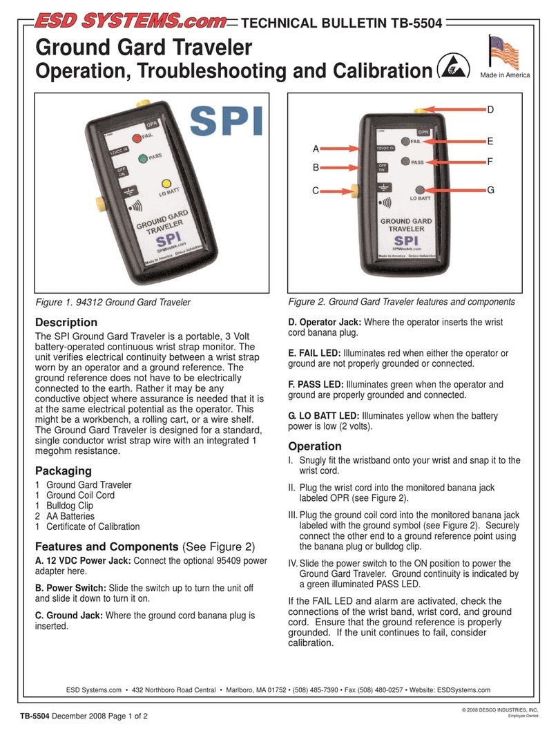
SPI Ground Gard Traveler Operating instructions

SPI

SPI Ground Gard Traveler Operating instructions

SPI 20-186-3 User manual

SPI

SPI 20-186-3 User manual

SPI 94200 Instruction Manual

SPI

SPI 94200 Instruction Manual

SPI 10-702-9 User manual

SPI

SPI 10-702-9 User manual

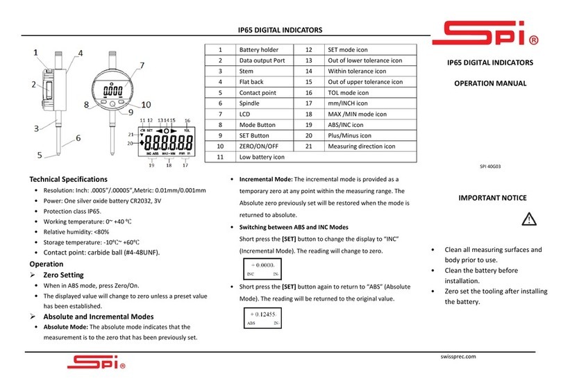
SPI 40G03 User manual

SPI

SPI 40G03 User manual

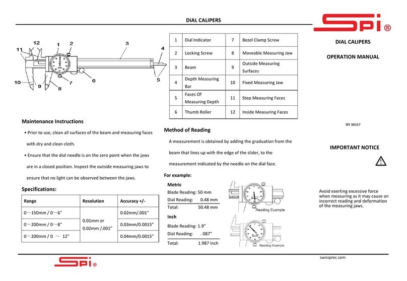
SPI DIAL CALIPER User manual

SPI

SPI DIAL CALIPER User manual

Popular Measuring Instrument manuals by other brands

ICP DAS USA PM-4324-400P-MTCP user manual

ICP DAS USA

ICP DAS USA PM-4324-400P-MTCP user manual

Klein Tools CL800E instruction manual

Klein Tools

Klein Tools CL800E instruction manual

GSi 18 user manual

GSi

GSi 18 user manual

GW Instek GFC-8270H manual

GW Instek

GW Instek GFC-8270H manual

YOKOGAWA AQ6376 user manual

YOKOGAWA

YOKOGAWA AQ6376 user manual

Transforming Technologies Resistance RANGER CM2800 instruction manual

Transforming Technologies

Transforming Technologies Resistance RANGER CM2800 instruction manual

WEHRLE MODULARIS Composite ETK-EAX operating instructions

WEHRLE

WEHRLE MODULARIS Composite ETK-EAX operating instructions

Precision Gold N73BZ instruction manual

Precision Gold

Precision Gold N73BZ instruction manual

Bosch FAA-420-RI-DIN installation guide

Bosch

Bosch FAA-420-RI-DIN installation guide

Siemens 5SV8001-6KK operating instructions

Siemens

Siemens 5SV8001-6KK operating instructions

NeurOptics NPi-200 Instructions for use

NeurOptics

NeurOptics NPi-200 Instructions for use

KAM Combi Cluster instruction manual

KAM

KAM Combi Cluster instruction manual

RS PRO RS-128M instruction manual

RS PRO

RS PRO RS-128M instruction manual

Consonics CyberTek Qualifier user guide

Consonics

Consonics CyberTek Qualifier user guide

Mitutoyo ID-N manual

Mitutoyo

Mitutoyo ID-N manual

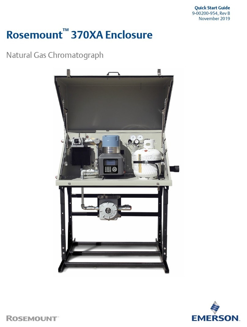
Emerson Rosemount 370XA quick start guide

Emerson

Emerson Rosemount 370XA quick start guide

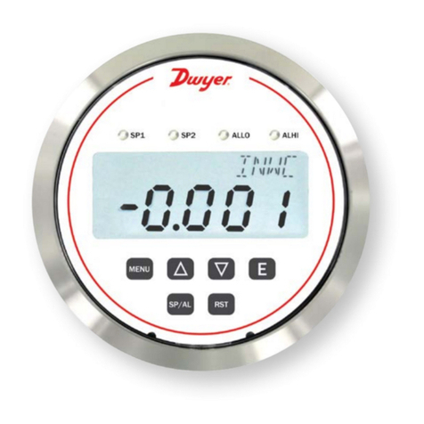
Dwyer Instruments RPME Series Specifications-installation and operating instructions

Dwyer Instruments

Dwyer Instruments RPME Series Specifications-installation and operating instructions

fafnir UM Series Technical documentation

fafnir

fafnir UM Series Technical documentation

manuals.online logo
manuals.online logoBrands
  • About & Mission
  • Contact us
  • Privacy Policy
  • Terms and Conditions

Copyright 2025 Manuals.Online. All Rights Reserved.