manuals.online logo
Brands
  1. Home
  2. •
  3. Brands
  4. •
  5. Sport-thieme
  6. •
  7. Accessories
  8. •
  9. Sport-thieme 115 0953 User manual

Sport-thieme 115 0953 User manual

Thanks for choosing Sport-Thieme equipment!
In order to enjoy this product please note the following instructions for safety, use and maintenance before assembly.
Assembly instruction Cat.-no.
: 115 0953
2392905
239 2918
113 6500
239 2400
239 2413
0118816 · © 2018 Sport-Thieme GmbH
Cat.-no. 115 0953:
Sport-Thieme®
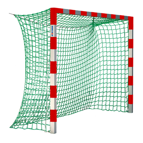
Handball Goal, 3x2 m,
Free-standing with Fixed
Net Brackets
Sport-Thieme®
Handball Goal
3x2 m, Free-standing with Fixed Net Brackets
Cat.-no. 113 6500:
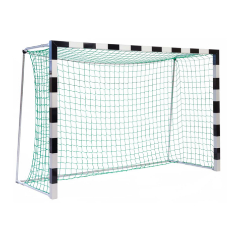
Sport-Thieme®
Handball Goal, 3x2 m,
standing in ground sockets.
With xed net brackets
D-38367 Grasleben ·Germany
sport-thieme.com · info @sport-thieme.com
Phone: +49 53 57 181 543 · Fax: +49 53 57 181 921
2
Assembly instruction Cat.-no.
115 0953; 113 6500
1. Scope of delivery
Please check the following content before assembly.
The following indicated quantities refer to 1 goal. In case of a delivery in pairs we double the amount cor-
respondingly. Pictured colours of proles are only samples and may dier from delivered proles.
Piece Description
1Galvanized steel ground tube Ø ¾“
1Crossbar, prole 80 x 80mm
2Upright, prole 80 x 80mm
1Hexagon screwdriver SW6, DIN 911, length approx. 470mm (only for goal in ground sockets)
Piece Description
2Aluminium cast corner joint
2Upright cap
1 Accessories
Piece Description
2Rigid net hoop
Piece Description
Following parts only for catalogue no.
113 6500 – goal in ground sockets
2Ground socket, length 300 mm
2Cap for ground socket
3
Assembly instruction Cat.-no.
115 0953; 113 6500
Accessories
Piece Description
32 Net holder
8Nut, 40 mm, thread M8
2Bush with thread M8, of aluminium round tube 20 x 5 mm, length 40 mm
6Plastic holder
8Hexagon socket screw M8 x 20, DIN 7991
8Hexagon socket screw M8 x 14, DIN 912
8Hexagon screw, M8 x 16, DIN 933
2Hexagon screw M8 x 90, DIN 931
2Hexagon screw M8 x 12, DIN 933
2Self-locking nut M8, DIN 985
4Self-locking cap nut M8, DIN 986
8Nut M8, DIN 934
4Ring nut M8 x 50
8Plug pin
1Hexagon screwdriver SW5, DIN 911, black
1Hexagon screwdriver SW6, DIN 911, length 120 mm
1Assembly instruction
4
Assembly instruction Cat.-no.
115 0953; 113 6500
2. Assembly of the goal
The following tools are necessary:
- 2 wrench/ring spanners 13 mm
- 1 mallet/hammer
- 1 drill Ø 1,5 mm
- 1 thin screw driver (for net hook xing if necessary)
a) Assembly of crossbar/uprights:
Lay crossbar and uprights on the ground, groove facing upwards and mitres joining. Stick at each goal frame corner 4 nuts
with thread M8, length 40 mm into the groove of the net hook rail (push 2 into the upright and 2 into the crossbar, see 1st
picture bottom left). Stick cast corner joint into crossbar’s end (see 2nd picture bottom right). Then add the upright. Take care
that the internal edge of corner upright/crossbar is nearly closed. The external edge should be somewhat open, see 3rd pic-
ture bottom left. Screw 2 hexagon socket screws DIN 7991, M8 x 20 in the internal corner (see 4th picture bottom right).
PfostenLatte
2. insert aluminium cast
corner joint
leave open external edge
3. push mitre of
internal edge close
together
4. screw hexagon socket
screws M8 x 20 slightly
1. push nuts into the groove
in angled position
screws screwless
the hexagon
socket screws
5
Assembly instruction Cat.-no.
115 0953; 113 6500
Then join upright and crossbar at the external edge and adjust upright and crossbar. Screw 2 hexagon socket screws DIN
7991, M8 x 20 in the external corner and tighten all screws (see picture bottom right).
Advice: Due to production tolerances of the aluminium cast corner joints problems during adjustment of corners may possibly
occur. Then shorten the stamps in the uprights with a flat le.
b) Assembly of net hoops at the top
Place rigid net hoops on the right and left side of crossbar/upright construction. Push nuts in the corners to the holes in the
upper angle. Fixing of net hoop at the top: Screw 4 socket screws M8 x 16 mm, DIN 933 screwless into the speed nuts (see
picture bottom left).
join and adjust corner
Between standing
6
Assembly instruction Cat.-no.
115 0953; 113 6500
c) Assembly of net hoops at the bottom
Screw from upright’s inside 4 hexagon socket screws M8 x 14, DIN 912 in the bottom end of the upright with extended Allen
key SW6, length 120 mm. Fix from the outside 4 nuts M8, DIN 934 (see 2nd to 4th bottom pictures). Then adjust net hoops at
the top and at the bottom and tighten all screws.
Assembly of net hoops upright - for goal in ground socket, cat.no. 113 6500:
The assembly is done as described above but with extended hexagon screw-driver SW6, length approx. 470 mm (see the follo-
wing pictures).
7
Assembly instruction Cat.-no.
115 0953; 113 6500
d) Assembly of caps
Stick caps in the open ends of uprights (see picture bottom left). Bore them with drill 1.5 mm through the holes provided in
the uprights. Then x plug pins with a hammer/mallet (see picture bottom right).
e) Assembly of ring nut
Stick from the inside ring nuts M8 x 50 through lateral and upper net hoop holes and x them with cap nuts M8, DIN 986 (see
bottom picture).
f) Assembly of ground tube
Stick hexagon screw DIN 931, M8 x 90 through bush of aluminium tube (see picture bottom left). Then push bush into the
ground tube (see picture bottom mid) and screw hexagon screw DIN 933, M8 x 12 through holes of bush and ground tube.
Tighten screw (see picture bottom right).
holes to x ring nuts
hole to x the
ground tube
screw ring nut from
the inside to the
outside and x with
cap nut
8
Assembly instruction Cat.-no.
115 0953; 113 6500
Fix ground tube between the net hoops (see 1st picture bottom left). Screw 1 self-locking nut M8, DIN 985 so that the nut out-
side is flush with the screw of the bush (see picture bottom right). Then unscrew hexagon screw at the ground tube (see 2st
picture bottom left). Finally push screw with self-locking nut completely into the ground tube so that the nut is directly xed
on the net hoop (see last picture bottom right). Then tighten all screws and nuts.
3. Assembly of the net
a) The net is not part of the delivery.
Fix net holders at the net rope. Bend open net holders a little and press rope into the holders. We recommend the following
distribution of net holders:
crossbar : 16 pieces
uprights : 8 pieces each
After having mounted all net holders x net at the goal construction. Erect the goal. Stick net holders in the net hook rail and
x them with a 90 degrees’ rotation. Use a thin screw driver if necessary (please avoid damages at the goal).
hole to x the
ground tube
2. unscrew screw
3. push screw with nut
completely into the
ground tube
1. nut outside flush
with screw
9
Assembly instruction Cat.-no.
115 0953; 113 6500
Fix net with plastic holders in the bottom part of net hoops. Cut o protruding ends of plastic holders
(see picture bottom right).
b) Fix ends of upper and lower tensioning rope at the mounted ring nuts. Cut o protruding rope ends (see bottom picture).
c) Dismantling of the net is also done by rotation of the net holders through 90 degrees. Use again a thin screw driver if neces-
sary.
10
Assembly instruction Cat.-no.
115 0953; 113 6500
4. Assembly of the ground sockets
a) For handball gates with a size of 3,00 x 2,00 m the distance of the ground sockets must be 3,08 m (middle socket – middle
socket = center distance).
b) Concrete ground sockets according to the sketch. Foundation dimensions: 800 x 800 x 800 mm.
c) Do not apply an acceleration mixture or antifreeze during as these adhesives may cause damages to the ground sockets.
d) After hardening of the concrete, the goal can be inserted into the sockets.
5. Maintenance, safety and storage instructions
This goal is only constructed for Handball and not for other purposes. Check all screwed
fastenings before use and repeat it from time to time. It has to be protected against over-
turning at any time.
Do not climb net or goal frame. It is not allowed to x additional parts or extensions at the
goal frame which may impair the safety of the goal (according to EN 749).
Check screwed fastenings regularly and change damaged and wearing parts if need be. The unit should be maintained once a
year by skilled personnel.
Notice
Due to our continuous quality check of products and equipment technical modications are possible.
To avoid damage and misuse goals have to be stored secured and in an upright position when not in use.
Only use water for cleaning the surfaces. Do not use alcohol or any aggressive chemicals!
All images and texts are intellectual property of Haspo Sportgeräte GmbH & Co. KG.
Any usage requires explicit permission.
11
Assembly instruction Cat.-no.
115 0953; 113 6500
12
Assembly instruction Cat.-no.
115 0953; 113 6500

Other manuals for 115 0953

1

This manual suits for next models

5

Other Sport-thieme Accessories manuals

Sport-thieme Small Training Goal 1,80x1,20 m Assembly instructions

Sport-thieme

Sport-thieme Small Training Goal 1,80x1,20 m Assembly instructions

Sport-thieme 11 113 6526 Assembly instructions

Sport-thieme

Sport-thieme 11 113 6526 Assembly instructions

Sport-thieme 259 4503 User guide

Sport-thieme

Sport-thieme 259 4503 User guide

Sport-thieme 1095601 Assembly instructions

Sport-thieme

Sport-thieme 1095601 Assembly instructions

Sport-thieme Small Training Goal 1,20x0,80 m Assembly instructions

Sport-thieme

Sport-thieme Small Training Goal 1,20x0,80 m Assembly instructions

Sport-thieme 247 1600 User manual

Sport-thieme

Sport-thieme 247 1600 User manual

Sport-thieme 116 3562 Manual

Sport-thieme

Sport-thieme 116 3562 Manual

Sport-thieme 113 5985 Installation guide

Sport-thieme

Sport-thieme 113 5985 Installation guide

Sport-thieme Trolley User manual

Sport-thieme

Sport-thieme Trolley User manual

Sport-thieme 115 0780 User manual

Sport-thieme

Sport-thieme 115 0780 User manual

Sport-thieme 11 201 0902 Assembly instructions

Sport-thieme

Sport-thieme 11 201 0902 Assembly instructions

Sport-thieme 113 6526 User manual

Sport-thieme

Sport-thieme 113 6526 User manual

Sport-thieme 113 5914 User manual

Sport-thieme

Sport-thieme 113 5914 User manual

Sport-thieme Soft trampoline 11 127 8705 User manual

Sport-thieme

Sport-thieme Soft trampoline 11 127 8705 User manual

Sport-thieme 11 242 1618 Assembly instructions

Sport-thieme

Sport-thieme 11 242 1618 Assembly instructions

Sport-thieme 115 6603 Manual

Sport-thieme

Sport-thieme 115 6603 Manual

Sport-thieme 115 2584 User manual

Sport-thieme

Sport-thieme 115 2584 User manual

Sport-thieme SunVolley Plus User manual

Sport-thieme

Sport-thieme SunVolley Plus User manual

Sport-thieme 11 115 2207 Assembly instructions

Sport-thieme

Sport-thieme 11 115 2207 Assembly instructions

Sport-thieme 115 9501 User manual

Sport-thieme

Sport-thieme 115 9501 User manual

Sport-thieme 11 116 3849 Assembly instructions

Sport-thieme

Sport-thieme 11 116 3849 Assembly instructions

Popular Accessories manuals by other brands

SKY PARAGLIDERS REVERSE 2 user manual

SKY PARAGLIDERS

SKY PARAGLIDERS REVERSE 2 user manual

Hortensus E6100 Series owner's manual

Hortensus

Hortensus E6100 Series owner's manual

STEINEL IR Micro LiveLink Information

STEINEL

STEINEL IR Micro LiveLink Information

Data Harvest Smart Wireless 1110PK manual

Data Harvest

Data Harvest Smart Wireless 1110PK manual

SEA SUNSET manual

SEA

SEA SUNSET manual

4O3A Azimuth Reader instruction manual

4O3A

4O3A Azimuth Reader instruction manual

Axis F1025 installation guide

Axis

Axis F1025 installation guide

Knick SE 503 Series Instructions for use

Knick

Knick SE 503 Series Instructions for use

BAT GIOTTO Use and maintenance instruction manual

BAT

BAT GIOTTO Use and maintenance instruction manual

Nittan Sensortec ST-PY-AS instruction manual

Nittan

Nittan Sensortec ST-PY-AS instruction manual

VWR Avantor VWR OPOX 11-3 operating manual

VWR

VWR Avantor VWR OPOX 11-3 operating manual

Honeywell DC515 P2 Series Getting started

Honeywell

Honeywell DC515 P2 Series Getting started

Omron ZFX-C10 COMMUNICATION user manual

Omron

Omron ZFX-C10 COMMUNICATION user manual

Anemoment TriSonica Mini user manual

Anemoment

Anemoment TriSonica Mini user manual

Steinberg UR22 Operation manual

Steinberg

Steinberg UR22 Operation manual

Awntech RN22 Owner's Manual & Installation Instructions

Awntech

Awntech RN22 Owner's Manual & Installation Instructions

Radio Bridge RBS101-WAT-RCZ2 user guide

Radio Bridge

Radio Bridge RBS101-WAT-RCZ2 user guide

Byron Home Easy HE-205 installation instructions

Byron

Byron Home Easy HE-205 installation instructions

manuals.online logo
manuals.online logoBrands
  • About & Mission
  • Contact us
  • Privacy Policy
  • Terms and Conditions

Copyright 2025 Manuals.Online. All Rights Reserved.