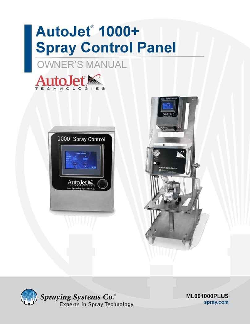
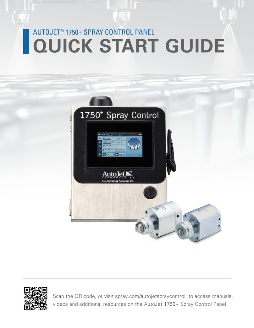
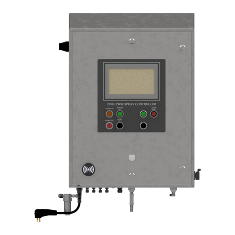
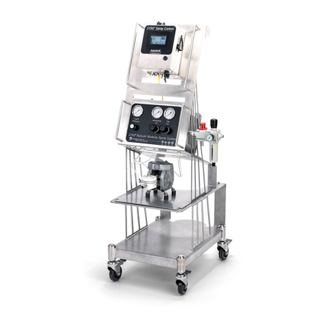
Spraying Systems AutoJet 2150+ User manual

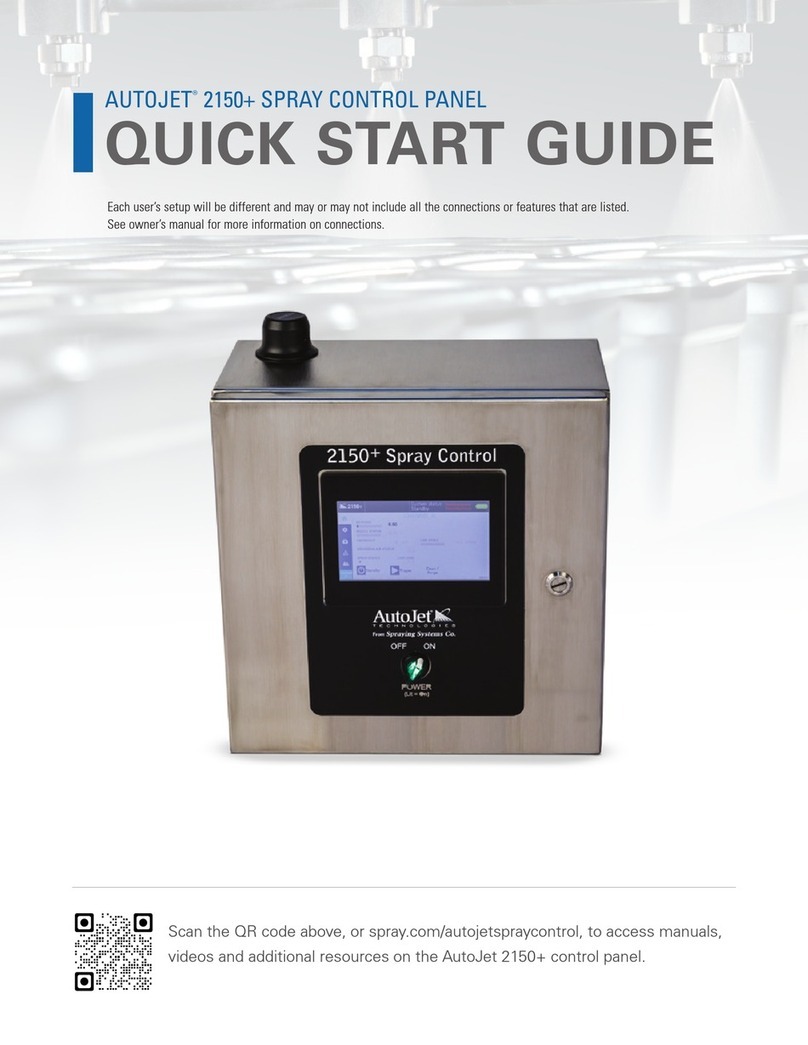
AutoJet® 2150+
Spray Control Panel
OWNER’S MANUAL
ML002150PLUS
spray.com

TABLE OF CONTENTS
1. Preface·······································································3
1.1 Important···························································3
1.2 How To Use This Manual ···································3
2. Safety·········································································3
2.1 General Safety Informaon ·······························3
2.2 Unpacking The System·······································4
3. 2150+ Overview·························································5
3.1 System Features·················································5
3.2 System Specicaons·········································5
3.3 Precision Spray Control (PSC)·····························6
3.4 Posion Or Mount The System··························7
3.5 Plug And Spray Connecons ······························7
3.6 Remote Connecon ···········································8
3.7 Screen Buons And Icons ··································8
3.8 HMI Operaons—Set Spray Parameters ···········9
3.9 Recipes·······························································9
4. 2150+ Home Screen·················································10
4.1 Home Screen—Channel A and B······················10
4.2 Home Screen Opons ······································11
4.3 Purge And Clean···············································12
5. General Sengs·······················································13
5.1 Sengs Screen·················································13
5.2 User Management Sengs······························14
5.3 User Groups ·····················································16
6. Supplying Air To The System····································17
6.1 Adjustments and Operaons···························17
7. Applicaon Sengs ·················································18
7.1 Spray Nozzle Sengs·······································18
7.2 Spray Timing Modes·········································22
7.3 Fixed Spray Time··············································22
7.4 Variable Spray Time ·········································25
7.5 Conguraon ···················································29
7.6 Recipe Sengs·················································31
7.7 Duty Cycle ························································33
7.8 Trigger······························································35
7.9 Tank Level Sensor·············································36
8. Pressure Sensor (Opon)·········································37
8.1 Liquid Pressure (Pressure Sensor)····················37
8.2 Pressure Sensor Spare Parts ····························38
9. Speed/Encoder (Opon)···········································39
9.1 Speed/Encoder··················································39
9.2 Encoder Selecon·············································· 40
9.3 Encoder Spare Parts·········································· 41
10. Flow Meter (Opon)···············································42
10.1 Flow Meter Sengs ········································ 42
10.2 Assembly Specicaons··································43
10.3 Flow Meter Spare Parts···································44
11. Faults And Alarms··················································· 44
11.1 Faults And Alarms Sengs······························44
12. Maintenance And Troubleshoong························45
12.1 Maintenance And Troubleshoong Sengs··· 45
13. Diagnoscs······························································ 47
14. Trigger Devices And Accessories····························· 47
14.1 Electric Nozzle Cord Set ··································47
14.2 Trigger Cable ··················································· 48
14.3 Photoelectric Object Sensor····························48
14.4 Color Sensor····················································49
14.5 Proximity Sensor ············································· 49
14.6 Trigger Interlock··············································49
14.7 Foot Switch······················································49
14.8 Hand Trigger Pendant ····································· 50
14.9 Thru-Beam Sensor··········································· 50
14.10 Laser Sensor (Short)·······································51
14.11 Laser Sensor (Long)········································51
14.12 Fault Output Signal ········································51
14.13 Fault Output cable Kit····································52
14.14 Extension Cable··············································53
14.15 Input Signal ···················································· 53
14.16 Level Sensor Input·········································· 54
14.17 Trigger Devices Overview·······························54
15. Faults And Troubleshoong····································55
15.1 Internal Components ······································58
16. Ethernet IP Manual (Oponal)································59
16.1 Studio 5000 Import Example···························59
16.2 Loading the Registered EDS File ·····················61
16.3 Ethernet IP Address List: Read Address··········63
16.4 Ethernet IP Address List: Write Address·········64
16.5 BIT Numbers, Faults, and Their Descripons·· 65
17. Spare And Replacement Parts ································ 66
3
1.1 IMPORTANT
The AutoJet® 2150+ Spray Control Panel and all components are produced, tested, and checked at the factory. The sys-
tem can be dangerous if used incorrectly. Read this manual carefully and pay aenon to any safety instrucons.
Operators must always follow the general safety instrucons in the working area and aim to prevent accidents.
The manufacturer reserves the right to make changes in standard construcon without prior nocaon.
Images and diagrams in this manual may not be exact representaons of the system conguraon.
1.2 HOW TO USE THIS MANUAL
This manual is intended to be a source of informaon for the operators and technicians who may be installing,
interacng with, or servicing/maintaining Spraying Systems Co.® systems and components.
This manual contains important safety warnings, installaon instrucons, operang instrucons, troubleshoong, and
maintenance informaon.
ICONS
WARNING: The User can be seriously injured, damage their health, and/or seriously damage the
system.
CAUTION: Product, process, or environment can be damaged or be in danger if the instrucons are
not followed correctly.
ATTENTION: Supplementary informaon for the user that draws aenon to possible problems.
SECTION 1
PREFACE
SECTION 2
SAFETY
2.1 GENERAL SAFETY INFORMATION
READ AND FOLLOW INSTRUCTIONS
All safety related and operang instrucons should be read before the system is operated. Follow all operang in-
strucons.
SERVICING
Do not aempt to service this system unless you have been trained or authorized to conduct repairs. Only authorized
and qualied service personnel should aempt to service this system. Service by unauthorized personnel will void
any warranes.
WARNING: Before performing any maintenance, make sure electrical power is o and that any air
and liquid pressure is bled from the system.
REPLACEMENT PARTS
This system has been designed with components that work together to provide the best system performance. When
replacement parts are required, only Spraying Systems Co.® recommended components should be used to maintain
proper system operaon, electrical and pneumac safety. The use of any unauthorized replacement parts will void
any warranes.
UNINTENDED USE
Use of Spraying Systems Co.® equipment in ways other than those described in the documentaon supplied with
the equipment may result in injury to persons or damage to property. Examples of unintended use of equipment:

4
• Using incompable materials
• Making unauthorized modicaons
• Removing or bypassing safety guards or interlocks
• Using incompable or damaged parts
• Using unapproved auxiliary equipment
• Operang equipment in excess of maximum rangs
REGULATIONS AND APPROVALS
Make sure all equipment is rated and approved for the environment in which it is used. Any approvals obtained for
Spraying Systems Co.® equipment will be voided if instrucons for installaon, operaon, and service are not followed.
All phases of equipment installaon must comply with federal, state, and local codes.
PERSONAL PROTECTIVE EQUIPMENT
Spraying Systems Co. strongly recommends the use of appropriate safety equipment when working in potenally
hazardous environments or with potenally hazardous chemicals. This safety equipment includes, but is not limited to,
the following:
• Protecve hat
• Safety glasses or face shield
• Chemical-resistant safety gloves and apron
• Long sleeve shirt and long pants
Users of this product should never place themselves in the path of the resulng spray. Users should consult and follow
the recommendaons of the Safety Data Sheet (SDS) of any chemical or uid sprayed using this system.
PRESSURIZED SYSTEMS
It is important to recognize proper safety precauons when using a pressurized spray system. When dealing with
pressure applicaons, the system pressure should never exceed the lowest rated component. Always know the system
and all component capabilies, maximum pressures, and ow rates.
WARNING: Fluids under pressure can penetrate skin and cause severe injury.
ATTENTION: Always remember to carefully read the chemical manufacturer's labels and SDS and
follow all direcons.
WARNING OF SHOCK HAZARD
To reduce the risk of electric shock, do not open the cover on electrical control panel. For service contact
Spraying Systems Co.® at 1-866-321-2250.
WARNING: Plug panels into a GFCI outlet.
WARNING: To prevent injury, avoid contact with potenally hot parts. Components can cause severe
burns. Do not aim the spray at any person or part of the body. Do not place any part of your body in
the spray paern.
2.2 UNPACKING THE SYSTEM
The system components come carefully packaged to protect them from damage. Use cauon when opening the crate.
The crate will contain all parts needed to install the unit. Parts of the unit may be wrapped in bubble wrap. Remove all
of the packaging material wrapping the system. Once unpacked and removed the from the crate, the system is ready
for installaon and connecon.
CAUTION: The packaging may contain exposed cables, hoses, or other components. Always exercise
cauon when opening boxes to avoid accidental damage or slicing of various components.

5
SECTION 3
2150+ OVERVIEW
The 2150+ is the advanced level oering in the Spray Control System (SCS) Series. It provides ON/OFF ming control
and liquid pressure control for both electrically- and pneumacally-actuated spray nozzles. The system comes in a
variety of design conguraons depending on the spray applicaon, therefore, you may or may not have all the
features described in this owner’s manual.
2150+ VERSIONS
• Single/Dual Channel, 48V nozzle driver (Standard)
• Single/Dual Channel, 24V nozzle driver (Oponal)
• High Capacity, 48V (Standard) nozzle driver/24V nozzle driver (Oponal)
3.1 SYSTEM FEATURES
The AutoJet® 2150+ Spray Control System provides precise liquid delivery and spray nozzle control in an aordable,
easy-to-use, turn-key soluon. The system can be used with water, oils, lubricants, inks, stains, water-based solvents,
and non-abrasive slurries. The system is designed to spray most non-ammable or non-volale materials. Liquids and
materials that ow with viscosies below 1000 cP at 68° F (20° C) can be sprayed with the correct spray nozzle and
controlled with this unique spray system soluon.
PLUG AND SPRAY COMPATABILITY
Plug and Spray provides quick electrical hook-up for all nozzles, an Air Control Package (ACP), triggers, and any other
compable SCS Series accessories - including a level sensor, pressure sensor, ow meter and line speed encoder. An
Ethernet bulkhead is included in the Plug and Spray array.
SPRAY CONTROL
• SCS Series uid delivery versions available: Pump, Pumpless, Pressure Pot, and Coang Supply Unit.
• Nozzle compability: air- or electrically-actuated, hydraulic or air atomizing nozzles.
• Recipe based ming: Create and store up to 20 user programmed recipes. (Oponal)
• Timing modes: Fixed/Variable spray me, and Fixed/Variable spray distance (Repeat funcon available for all four
modes).
• Pressure and ow monitoring: Pressure sensor and ow meter accessories allow for real-me monitoring of
current spray parameters.
3.2 SYSTEM SPECIFICATIONS
• Spray control panel weight: 37 lbs. (16.3 kg) approximate
• Max nozzle distance: 15 m (55 .)/min
• 1-100% duty cycle adjustment for electric spray nozzles.
• Input for sensor or remote trigger/relay dry contact
• Independent ming ranges for spray and delay adjustable from 0 to 9,999.99 seconds
• Max. no. of 10000AUH-03 PulsaJet Spray Nozzles: 16 per channel
• Max. no. of 10000AUH-10 PulsaJet Spray Nozzles: 5 per channel
• Max. no. of 10000AUH-0050 PulsaJet Mini Spray Nozzles: 8 per channel (48V driver version only)
POWER REQUIREMENTS
• 110/230, 50/60 Hz, 1 Ph, 8.8A. (Plug into GFCI outlets)

6
SPECIFICATIONS:
• 7” HMI Touch Screen control and display
—HMI window kit (oponal)
• Wall mountable stainless steel enclosure, washdown
with door closed
—Power ON/OFF switch-Power on indicator light
—Power cord, 6 (2m) length
• Power input: 120VAC, 50/60, single phase
—Global compability mul-voltage power cords
available.
• Built-in Wi-Fi wireless access point.
DIMENSIONS
• Width: 16 inches
• Depth: 10 inches
• Height: 18.5 inches
STANDARD ENVIRONMENTAL SPECIFICATIONS:
• To be installed indoors
• Min. ambient temperature: 41°F
• Max. ambient temperature: 104°F
• Max. humidity: 90%
• Not explosion proof (non-Ex)
• Height above sea level: <3,280 feet
SINGLE CHANNEL
• 48V nozzle driver (Standard)
—48Vdc/10A power supply
• 24V nozzle driver (Oponal)
—24Vdc/10A power supply
DUAL CHANNEL
• 48V nozzle driver (Standard)
—Two (2) 48Vdc / 10A power supplies
• 24V nozzle driver (Oponal)
—Two (2) 24Vdc / 10A power supplies
HIGH CAPACITY
• 48V nozzle driver (Standard)
—Two (2) 48Vdc / 10A power supplies
• 24V nozzle driver (Oponal)
—Two (2) 24Vdc / 10A power supplies
3.3 PRECISION SPRAY CONTROL (PSC)
The PulsaJet® automac spray nozzle is an electrically-actuated hydraulic atomizing nozzle. This nozzle sprays the
product in a controlled way using a Pulse Width Modulaon (PWM) algorithm to control the sprayed amount without
aecng the spray angle. PWM is the fundamental control principle that allows a signicant reducon in ow by
regulang the relaonship between the on/o mes that the nozzle operates.
Short pulses of o-me and longer pulses of on-me produce a spray paern that appears connuous, but actually
reduces the overall ow delivered to the target surface. This provides beer ow control with larger spray ps that are
less prone to clogging. The droplet size is aected by the pressure of the liquid. With PSC, the droplet size and spray
angle are independent of the liquid ow because the nozzle can work at the
same liquid pressure for variable liquid ows.
PSC involves switching the spray nozzle on and o repeatedly at a controlled
rate, called the modulang frequency. The modulang frequency is the number
of mes the nozzle is switched on and o in one second and is measured in
Hertz (Hz). If a spray nozzle is switched on and o 10 mes per second, the
modulang frequency is 10 Hz. The me from when the nozzle turns on to the
next me the nozzle turns on is called the period, in this case 1/10th of a
second.
Within a single period, the nozzle is switched on, then o. The me that the
nozzle is on, divided by the total me of the period, gives a percentage which is
called the duty cycle. For example, if the period is 0.10 seconds, and the nozzle
is on for half of that me, then the duty cycle is 50%. For the same period, if the
nozzle is on for 0.08 seconds then the duty cycle is 80%. Therefore, at an 80%
duty cycle, the ow will theorecally be 80% of the maximum ow rate (= 100%
ow rate) at a given pressure for the nozzle. Using PSC, the ow rate for a spray
applicaon can be easily controlled without the need to adjust the spray
pressure or spray p.

7
3.5 PLUG AND SPRAY CONNECTIONS
3.4 POSITION OR MOUNT THE SYSTEM
The system should be placed in a convenient locaon near the spray applicaon. A properly grounded power outlet
must be easily accessible.
—Determine if the unit will be free-standing or wall mounted.
CONTROL PANEL ONLY VERSION
Note: The Control Panel Only version should be wall mounted.
Install wall anchors that are designed to support at least 25 lbs., according to the anchor manufacturer’s specicaons.
The mounng holes are on 14.5" centers and are made for 0.5" screws.
Channel A and Channel B bulkheads (boom of 2150+)
7” HMI
Power Switch
Plug and Spray Connecons
(boom of spray control panel)
Power Cord
All the connecons are the same as the full system. Located on the boom of the panel the connecons are as follows.
Plug provided power cord into the exisng whip cord at the boom of panel.
• Main - Used for the output connecon for all electric spray nozzles and cylinder air.
• Trig - The input connecon for the system trigger or sensor.
• Fan/Atm Air - The output connecon for the fan/atomizing air.
• T. int. - Used for the oponal trigger interlock or level switch input.
• Remote Setpoint (Duty Cycle) - 4-20 mA, Analog input is accessible through this connecon.
• Level - Used for Tank Level sensor. Connect the sensor to the “Level” connecon. On the HMI, go to Applicaon
Sengs to acvate the level sensor sengs.
• Pressure - Liquid Pressure settings require an active pressure sensor connection to the panel. When connected, the
input settings are to be calibrated to match the specifications of the pressure sensor. Connect the pressure cable to
the “Pressure” connection.
• Encoder - (Speed) settings require a connected line speed encoder. Connect the sensor to the “Encoder” connec-
tion. On the HMI, go to Application Settings to activate the encoder.
• Flow - Connect the unit and then connect the “Flow” meter cable to the panel. Set the input values to match the
specicaons of the ow meter.
Dual Channel Spray Control Panel

8
3.6 REMOTE CONNECTION
Users can connect to the 2150+ with a mobile device via Wi-Fi to create an access point. Once set-up is complete, you
can adjust sengs, view alarms, troubleshoot, review maintenance schedules, and more on the connected mobile
device. The 2150+ Preventave Maintenance (PM) scheduler allows the user to set various maintenance reminders by
months or number of cycles. An alarm will appear on the HMI when the maintenance is due.
SMART DEVICE CONNECTION
1. Go to the Play Store or Apple App store and download a VNC viewer app, such as RealVNC Viewer.
2. Power on the 2150+ (if system is not already on).
3. In Wi-Fi sengs on your mobile device, locate the Wi-Fi SSID, typically SSCO_xxxxxx. Select connect and enter the
default password of SSCO2150.
Note: There is a chance that your network administrator blocks this type of connecon.
4. Finally, open VNC Viewer and connect to the 2150+ at: 192.168.0.20:5900.
3.7 SCREEN BUTTONS AND ICONS
SIDE BAR NAVIGATION
Navigate to home screen.
Navigate to sengs screen.
Navigate to diagnoscs screen
Navigate to alarms screen, turns orange with
an acve alarm present.
Switch to a dierent user.
TOP BAR STATUS INFORMATION
Navigate to about screen.
Recipes
Displays current system status.
Reset Alarm
SCREEN BUTTONS
Field is editable
Toggled On
Toggled O
Standby or Run
Trigger

9
3.8 HMI OPERATION—SET SPRAY PARAMETERS
1. Set the system to manual mode. Disconnect the nozzles. Set all pressure regulators to 0. Turn on the main air
pressure and increase liquid pressure gradually to ush the system. Everything is now ushed except for the
nozzles.
2. Connect the nozzles, set the pressure regulators to the required pressure and check for leakage.
3. If the nozzle type isn’t set, go to the Spray Nozzle Sengs secon of this manual.
TO START THE SYSTEM
1. Verify the system status is in “Run” mode (top bar, right corner).
2. If not, press “run” unl the system is in “RUN” mode.
3. Be sure a recipe is selected If you have purchased the oponal soware upgrade and the desired PWM setpoint is
set in the recipe (between 1% and 100% depending on the applicaon).
3.9 RECIPES
A recipe is a pre-congured set of ming and spray parameters designed to help transion quickly from one applicaon
to the next. The 2150+ is capable of storing up to 20 user created recipes.
By default, the 2150+ control panel has simple ming to operate PulsaJet electric spray nozzles. The recipe funcon can
be added anyme by entering an unlock code as shown below. A recipe can be loaded by selecng it from the
dropdown menu and clicking “Apply” to transfer the sengs to the 2150+. If you edit the currently selected recipe, you
must press “apply” again for the changes to be applied.
Preprogrammed recipes can be accessed quickly from any screen by selecng the recipe secon of the top bar. The
recipe sengs secons contains four tabs. The drop down list near the top of the page allows you to select which
recipe you would like to view, edit, or apply as the current spray parameters.
Enter recipe code in the box at the boom of the screen

10
4.1 HOME SCREEN—CHANNEL A AND B
The 2150+ is available in either a single or dual channel conguraon. In a single channel system, there will be no
channel name or designaon shown on the home screen. In a dual channel system, the Channel A label will be visible in
the lower le corner of the screen and under the top bar.
In a dual channel system, Channel B is also available for conguraon. To access Channel B, press the Channel A
labeled box in the lower le-hand corner of the screen. Channel B appears with a dierent color home screen
background color to allow for easy idencaon of the currently selected channel.
Home screen, Channel A for a dual channel 2150+
Home screen, Channel B for a dual channel 2150+
Selecng the 2150+ icon in the top le-hand corner of the screen will bring up the About screen for the spray control
panel.
SECTION 4
2150+ HOME SCREEN

11
4.2 Home Screen Options
The home screen at the top and side bars will always be visible and accessible.
Setpoint: Displays the congurable mode in the applicaon you are set in.
Nozzle status: Displays the current nozzle spray status as a percentage of the maximum ow rate.
Atomizing air status: Atomizing Air Status and spray status are read-only representaons of the current status.
Adjust atomizing air in sengs, and toggle the spray status by using the run or trigger buons.
Spray status: Shows whether the nozzle is currently spraying or not.
Frequency: is read only representaons of the current status and displays the actual cycles per minute.
Low level: will display if a level sensor is connected and congured for the 2150+.
Liquid pressure, remote setpoint, line speed (duty cycle), ow rate, and applicaon rate conguraons are based on
the current spray parameters (if you have these applicaons)and are read-only values.
STANDBY/RUN
Using this Toggle buon, you can swap between Run and Standby states.
• Run: The system will spray if it is triggered.
• Standby: The system will stop spraying and will not react to a new trigger signal.
If the system is busy spraying, it will nish the “follower” for the air output to cleanly stop spraying.
TRIGGER
The trigger buon is only shown if the trigger source has been set to “Buon on home screen” in “Trigger sengs”.
Depending on the sengs, you will have:
• Fixed spray mode, Momentary buon (single shot mode): starts a spray when clicked.
• Variable spray mode, Toggle buon: starts & stops a spray when clicked.
CLEAN/PURGE: Access or trigger the clean and purge cycle sengs.
2150+ Home Screen

12
PURGE
The purge cycle is commonly used to empty the uid lines of liquid, or as an addional way to drain a tank or pressure
pot.
The purge cycle automacally sets the nozzle duty cycle to 100% (fully open) and requires the operator to manually
turn the cycle on or o using the labeled indicator. The cycle will connue unl it is manually turned o. The other
values are not editable while the purge cycle is acve.
CLEAN
The clean cycle is commonly used to clear a nozzle that appears to be clogged and requires the operator to set three
editable values.
These values include:
• Clean Duty Cycle — Set between 1–100%
• Max Cycle Speed—Set between 60–5,000 cycles/minute
• Clean Time—Set between 1–250 seconds
4.3 PURGE AND CLEAN
Purge and clean cycles can be toggled on or o with their labeled On/O indicators at the boom of the screen. A blue
indicator with the dot on the right side shows the currently selected and acve cycle.
Purge and Clean sengs screen

13
SECTION 5
GENERAL SETTINGS
General sengs relate to the spray control panel itself and how operators interact with the 2150+.
5.1 SETTINGS SCREEN
The 2150+ allows operators to manage users and user sengs, change the language (where applicable), view system
informaon, and view the acvity log.
LANGUAGE
Here you will be able to change the language of the user interface text if available.
ABOUT SCREEN
This screen displays informaon about the system. You can nd the following informaon in the about screen:
• Spray controller serial number
• Spray controller soware version and revision number
• Spray controller/panel upme
• User interface panel soware version/hardware descripon
• Current date/me
Sengs screen

14
ACTIVITY LOG
The 2150+ tracks all changes to crical sengs and records which users make these changes; this informaon is
available in the acvity log. Users within the User Group cust_admin can view these acvity reports on the 2150+ or
export the acvity report via a USB sck.
5.2 USER MANAGEMENT SETTINGS
The 2150+ allows you to edit and/or create your own users so that each person who interacts with the system can have
their own personal login details.
Note: When the system is started for the very rst me, and for every reboot thereaer, it boots up to “default” (user)
which has admin rights (which can edit all sengs).
ATTENTION: A system restart is required to apply any changes made to user sengs.
Note: Should it ever be required contact your local Spray Specialist to receive instrucons on how to perform a total
system reset to factory sengs.
Login or switch user screen
Users buon
User management screen
Acvity Log Screen
Switch User
Sign out the current user by signing in a new user. This screen will also appear when selecng the users icon on the
le menu bar.

15
CHANGE PASSWORD
Allows you to change the password of the user that is
currently logged in. Enter the user’s current password then
enter the desired new password. Select “Change” to conrm
the acon.
Change password screen
ADD USER
Create a new user and assign them to a User Group. Ensure
that you use the drop-down menu to pick the correct user
group. Select “Add” to add the user to the 2150+ user list.
EDIT USER
Edit the selected user’s properes. You can change the
user’s password for them, or change their User Group.
Edit user screen Add user screen
SETTINGS
The Sengs opon within Add new user gives you
addional opons.
You can:
• Require the new user to change their inial password
on their rst login
• Change how long the new user may remain logged in
without any acvity
• Seng the value to 0 will leave the user logged in unl
they choose to log out, or the system is rebooted.
Add new user—sengs
DELETE USER
This screen allows a created user to be deleted. You must
select the username and group of the user you want to
delete, then select “Delete” to remove the user.
Delete User Screen
LOG OUT
Yes or no choice to log out the current user. The 2150+ will
return to the “default” user aer someone logs out.

16
5.3 USER GROUPS
The system contains four preloaded users (username and password sets) that are the factory (default) sengs. Users
can choose to use (or edit) these exisng users or create new users as they see t.
Each of these default users has a dierent level of user rights to interact with the system based on their selected User
Group. It is very important to pay close aenon to the selected User Group for each current and created user. The
table below shows the factory default users, user groups, and user rights. The minimum password length for all user
groups is four (4) characters, and all user groups have access to basic spray control panel features.
Factory (Default) User Rights and Sengs
Default
Username
Inial
Password User Group
Log O
Time (min)
Advanced
Features
Edit/Add
Users
Reboots
to User
operator oper operators n/a
default default cust_admin n/a xxx
admin admin cust_admin 15 xx
SSCO 60189 admin 15 xx
USER GROUP:
Operators
These users can trigger the system and put it in standby mode. Operators can change the duty cycle setpoint. All other
funcons are disabled or read-only for users in the operator user group.
• The factory sengs user “operator” is a member of this user group.
Cust_admin
These users have full control over all system sengs and can edit or create new users.
• The factory sengs user “admin” is a member of this user group.
Admin
There is a fourth factory sengs user “SSCO” that is included with the system in User Group admin.
This user is included as a backup opon to reset User Group cust_admin passwords if they are lost.
Do not use the “SSCO” user for daily operaon of the unit. User Group admin and User Group cust_admin have the
exact same access rights.
ATTENTION: A system restart is required to apply any changes made to user sengs.
Default Username:
Inial startup and all reboots of the system will load into the factory sengs “default” user prole.
Under factory sengs, the user “default” is within the user group default, which has the exact same level of access as
user group cust_admin.
• With factory sengs, this user has full control over the system and can edit or create new users.
• Users can edit this user to change its access level.
• Can be changed to user group “operator” to remove edit access.
• Can set an Inacvity logo me to require someone using the system to log in with their personal credenals aer
a set period of me.

17
SECTION 6
SUPPLYING AIR TO THE SYSTEM
6.1 ADJUSTMENTS AND OPERATIONS
1. Turn the red valve on the air inlet valve/regulator/lter clockwise to the on posion. Turn regulator that is on top of
the air lter to an air pressure between 40-100 psi (2.8-6.9 bar). Air pressures higher than this will shorten the life of
the pump.
2. Adjust the regulated air pressures (regulators on front panel).
If applicable, depending on the spray system you may have anywhere from Liquid Pressure regulaon only to
Liquid Pressure; Pump Air (preset); Atomizing Air (drop size); Fan Air (spray angle/paern).
3. Each air control line is equipped with a manual air pressure regulator. The regulators can be adjusted by rst pulling
up on the knob to unlock the regulator and then turning clockwise to increase and counterclockwise to decrease the
pressure.
4. When the desired air pressure is reached, press down on the knob to lock it in place.
Note: The system is equipped with cylinder air for air actuated spray nozzles. Cylinder air pressure is equal to the inlet
air pressure to the system. It is not regulated; therefore, you must provide a minimum of 45 psi (3.1 bar) to the
system. It must be above 45 psi (3.1 bar) to actuate air actuated nozzles like Spraying Systems Co.® 1/4JAU
series.
5. Adjust the Liquid Pressure regulator. For pump version ensure that the pump inlet air valve is in the “open” posion.
The regulator can be adjusted by rst pulling up on the knob and then turning clockwise to increase and
counterclockwise to decrease the pressure. When the proper liquid pressure is reached, press down on the knob to
lock it in place.
Air Connecon Specicaons
2150+ Home Screen

18
Applicaon sengs allow you to customize the spray parameters to achieve the desired spray coverage and ow rates.
These sengs will also allow you to congure certain 2150+ accessories, such as the pressure sensor, ow meter, or
line speed encoder.
Note: Applicaon Sengs and Recipe Sengs conguraon are the same. Use recipe funcon to congure most
sengs if the recipe feature is included in your system conguraon.
7.1 SPRAY NOZZLE SETTINGS
Note: See Conguraon secon or Recipe Sengs for more informaon on ming sengs.
Main Connecon Specicaons:
The Nozzle Sengs screen allows for the eding of the Nozzle type and Cycle Speed.
—Nozzle Type: nozzle family selecon, atomizing air selecon and ancipator/follower me.
—Cycle Speed: allows for the eding of the minimum and maximum cycles per minute.
Nozzle sengs screen
SECTION 7
APPLICATION SETTINGS
Applicaon Sengs
Color Code: Main
Pin
#Color Descriptio
n
1Brown PWM +
2white Fault
3Blue PWM -
4Black N/A

19
ANTICIPATOR/FOLLOWER TIME
The system will start spraying when it receives a trigger signal and stop when the trigger signal is removed.
If the system is equipped with an air atomizing nozzle, the 2150+ will switch the air output on before it starts spraying
to allow the spray paern to develop fully. When the system stops spraying, the air will connue for a short period
aer to guarantee no large droplets can drip o of the nozzle. Max me for both is 10 seconds.
Note: The ancipator me must not be shorter than the start delay me set in the ming sengs.
When a spray paern is generated where the o me < (ancipator me + follower me), the air output remains on
for the duraon of this paern.
Ancipator-Follower
Overlapping anticipator / follower sequence
Selecng Nozzle Type:
—Nozzle Family: Select the type of nozzle supplied with the system.
—Enable Atomizing Air if required.
—Advanced nozzle sengs allows for eding the PWM Waveform sengs.
Eding nozzle type

20
PARAMETERS—ADVANCED NOZZLE SETTINGS
For custom applicaons, it is possible to change the properes of the nozzle manually. These sengs should only be
modied by instrucon from qualied SSCO personnel except for the nozzle cycle count.
WARNING: Incorrect sengs can permanently damage the spray nozzle!
Negave Pulse: Pulse me in milliseconds
• Used to speed up the closing of the electric spray nozzle, duraon is dependent on nozzle model and supply
voltage.
V Hold: Holding voltage in V
• Aer the posive pulse, the signal drops to a hold voltage. This voltage is dependent on the type of nozzle and the
liquid pressure. 24V is a safe value for this, but it can somemes be lowered to minimize power consumpon and
heang of the spray nozzle.
Gun (Nozzle) Oset: Oset me in milliseconds
• The dierence in the opening and closing me of the PulsaJet nozzle can be corrected by using the oset value.
The default value is 0ms. For example: If the oset value is set to -1ms, the on period will be decreased by 1ms and
the o period will be increased by 1ms.
If a nozzle wear cycle count alarm has been acvated, the counter must be reset in this screen aer the nozzle has
been replaced.
Eding advanced nozzle sengs
Other manuals for AutoJet 2150+
1
Table of contents
Other Spraying Systems Control Panel manuals

Spraying Systems
Spraying Systems AutoJet 1000+ User manual

Spraying Systems
Spraying Systems AUTOJET 1750+ User manual

Spraying Systems
Spraying Systems AutoJet 2150+ User manual

Spraying Systems
Spraying Systems AutoJet 2850+ User manual

Spraying Systems
Spraying Systems AutoJet 1000+ User manual

Spraying Systems
Spraying Systems AUTOJET 1550+ User manual

Spraying Systems
Spraying Systems AutoJet 1000+ User manual

Spraying Systems
Spraying Systems AUTOJET 1750+ User manual

Spraying Systems
Spraying Systems AutoJet 1000+ User manual

Spraying Systems
Spraying Systems AutoJet 1750+ User manual