English
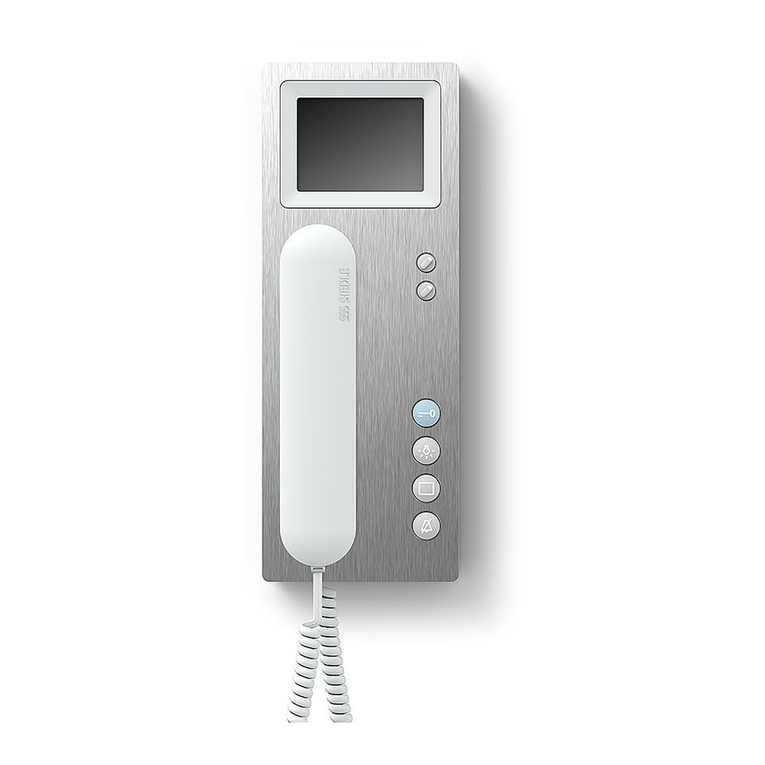
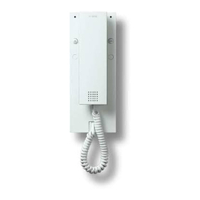
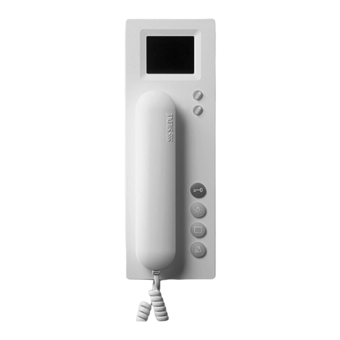
Comfort bus telephone with colour
monitor for door and internal
telephony.
Functions:
Calling, speech, vision, door
•
release and storey calls
Colour monitor 8.8 cm (3.5”)
•
Integrated video memory for 28 •
pictures, upgradable with SD card
Door release and light button
•
Keys for switching and control •
functions
Internal speech communication
•
display of switching statuses •
Silencing button for the ring tone•
11 ring tones•
Call and speech volume can be•
modied in 5 stages
Monitor button for current picture
•
5-way button for video memory •
and zoom function
Video memory function (only with
•
additional installation)
Intercom functions
Call forwarding
•
Internal group call•
Collective announcement•
Doormatic•
Callback•
Setting an internal callback•
Electrical voltage
Mounting, installation and servicing
work on electrical devices may only
be performed by a suitably qualied
electrician.
Electrostatic charging
As a result of electrostatic charging,
direct contact with the circuit board
can result in destruction of the
device. Direct contact with the circuit
board must therefore be avoided.
Scope of delivery
BTCV 850-... (Base plate and
•
housing with circuit board)
Receiver
•
Spiral cable•
Dummy card for SD card slot•
Operating instructions for the•
end user
This product information
•
Mounting
Strip back cable to appr. 80 mm.
Recommended mounting height
1
appr. 1.50 m to centre device.
Open the device from the back
2
by releasing the base plate with the
locking lever.
When mounting directly on the
3
wall, fasten the base plate using
4 screws, paying attention that
the plate is the right way up (top
marking).
When mounting on a switch box,
4
use the screw openings in the centre
of the device, paying attention that
the plate is the right way up (top
marking).
Install in accordance with the AS
5
diagram. The cores of the installa-
tion cable must be stored inside the
free installation space in the base
plate.
Insert the coloured plug of the
6
spiral cable into the socket at the
housing. A distinct click is audible
when the plug is correctly inserted.
Insert the other end of the spiral
7
cable into the receiver until the plug
clicks audibly into place. This con-
nection can no longer be detached.
Slot the housing into the base
8
plate and close by applying a light
pressure.
Dismantling
To remove the housing, press
9
the lock upwards using a at blade
screwdriver. The circuit board and
receiver remain on the upper part of
the housing.
Lettering
The lettering panel can be
10
inscribed to indicate the button
functions. The see-through panel
can be lifted at the side.
Terminal assignment
TaM/TbM Input In-Home bus
TaM/TbM Throughput
In-Home bus
ERT/ETb Storey call button
+M/-M Additional supply
20–30 V DC for video
memory function and
door parallel call
S1/S1 Potential-free contact
for additional bell
Commissioning
Installation, commissioning and
programming are described in the
system manual (enclosed with line
rectiers BNG/BVNG 650-... ).
Note
As in the as-delivered / de-energized
status, the contact position of the
bistable relay (contact S1/S1) cannot
be dened, the bus supply to the
device must be connected before-
hand to ensure that the bistable
relay functions correctly.
Video memory
The device‘s video memory is only
active when the bus telephone has
a supplementary power supply. It
stores the last 28 pictures taken by
the door camera. In the event of a
power failure, the video memory is
deleted.
Setting the language, date and
time
After rst switching on the monitor,
the language must be selected. The
display then changes over to the
input of date and time.
Assigning the monitor buttons
The monitor is operated using a
5-way button. The Enter key is used
to switch on the monitor or conrm
a selected function. The control but-
tons are used for navigation within
the different menu levels.

