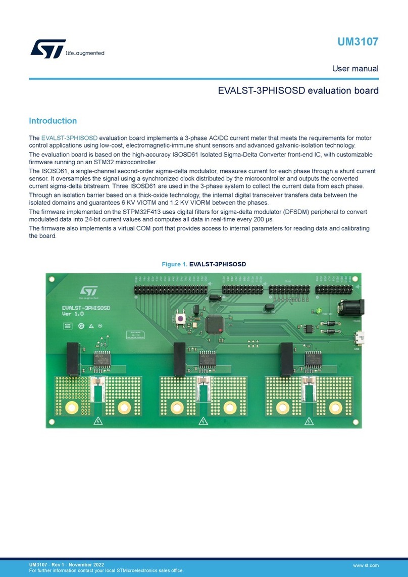
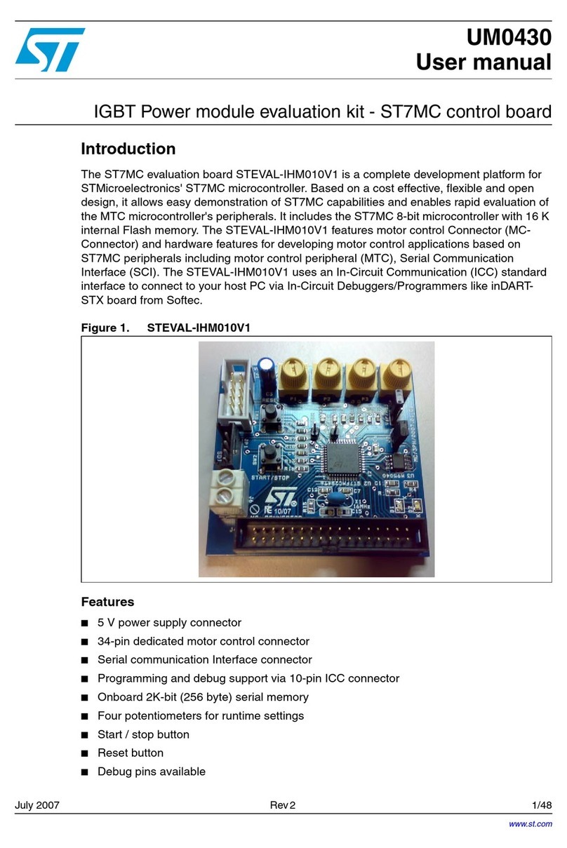
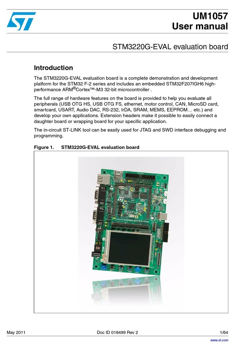
ST STM3210B-EVAL User manual

February 2010 Doc ID 13472 Rev 5 1/46
UM0426
User manual
STM3210B-EVAL
evaluation board
Introduction
The STM3210B-EVAL is an evaluation board for STMicroelectronic’s ARMTM Cortex-M3
core-based STM32F10x 128 K microcontrollers. It is designed as a complete development
environment for the STM32F10x microcontrollers with full speed USB2.0, CAN2.0A/B
compliant interface, two I2C channels, two SPI channels, three USART channels with
smartcard support, internal 20KB SRAM and 128KB Flash, JTAG and SWD debugging.
With a complete range of hardware evaluations features, the STM3210B-EVAL board is
designed to help developers evaluate all device peripherals (such as USB, motor control,
CAN, MicroSD Card™, smartcard, USART) and develop their own applications. Extension
connectors make it possible to easily connect a daughterboard or wrapping board for a
specific application.
This user manual provides information on using the STM3210B-EVAL board and its
hardware features.
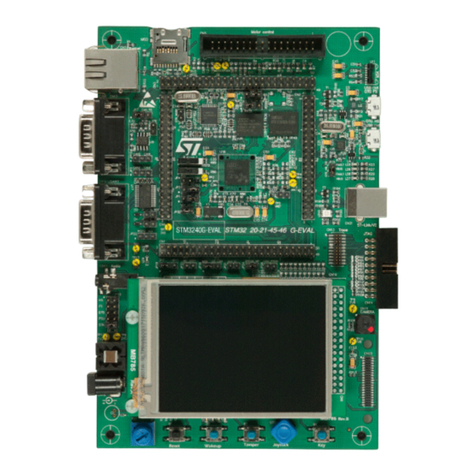
Figure 1. STM32F10X 128 K evaluation board (STM3210B-EVAL)
www.st.com
www.BDTIC.com/ST

Contents UM0426
2/46 Doc ID 13472 Rev 5
Contents
1 Overview . . . . . . . . . . . . . . . . . . . . . . . . . . . . . . . . . . . . . . . . . . . . . . . . . . 4
1.1 Features . . . . . . . . . . . . . . . . . . . . . . . . . . . . . . . . . . . . . . . . . . . . . . . . . . . 4
1.2 Order code . . . . . . . . . . . . . . . . . . . . . . . . . . . . . . . . . . . . . . . . . . . . . . . . . 4
2 Hardware layout and configuration . . . . . . . . . . . . . . . . . . . . . . . . . . . . . 5
2.1 LCD configuration . . . . . . . . . . . . . . . . . . . . . . . . . . . . . . . . . . . . . . . . . . . . 8
2.1.1 MB895/S or MB542 board version B-01 or later . . . . . . . . . . . . . . . . . . . 8
2.1.2 MB542 board version B-00 or earlier . . . . . . . . . . . . . . . . . . . . . . . . . . . . 9
2.2 Power supply . . . . . . . . . . . . . . . . . . . . . . . . . . . . . . . . . . . . . . . . . . . . . . . 9
2.3 Boot option . . . . . . . . . . . . . . . . . . . . . . . . . . . . . . . . . . . . . . . . . . . . . . . . 10
2.4 Clock source . . . . . . . . . . . . . . . . . . . . . . . . . . . . . . . . . . . . . . . . . . . . . . . 11
2.5 Reset source . . . . . . . . . . . . . . . . . . . . . . . . . . . . . . . . . . . . . . . . . . . . . . 11
2.6 Audio . . . . . . . . . . . . . . . . . . . . . . . . . . . . . . . . . . . . . . . . . . . . . . . . . . . . 12
2.7 Serial flash . . . . . . . . . . . . . . . . . . . . . . . . . . . . . . . . . . . . . . . . . . . . . . . . 12
2.8 CAN . . . . . . . . . . . . . . . . . . . . . . . . . . . . . . . . . . . . . . . . . . . . . . . . . . . . . 12
2.9 RS-232 . . . . . . . . . . . . . . . . . . . . . . . . . . . . . . . . . . . . . . . . . . . . . . . . . . . 13
2.10 Motor control . . . . . . . . . . . . . . . . . . . . . . . . . . . . . . . . . . . . . . . . . . . . . . 13
2.11 Smartcard . . . . . . . . . . . . . . . . . . . . . . . . . . . . . . . . . . . . . . . . . . . . . . . . . 13
2.12 MicroSD Card . . . . . . . . . . . . . . . . . . . . . . . . . . . . . . . . . . . . . . . . . . . . . . 14
2.13 Temperature sensor . . . . . . . . . . . . . . . . . . . . . . . . . . . . . . . . . . . . . . . . . 14
2.14 Analog input . . . . . . . . . . . . . . . . . . . . . . . . . . . . . . . . . . . . . . . . . . . . . . . 14
2.15 IrDA . . . . . . . . . . . . . . . . . . . . . . . . . . . . . . . . . . . . . . . . . . . . . . . . . . . . . 14
2.16 USB . . . . . . . . . . . . . . . . . . . . . . . . . . . . . . . . . . . . . . . . . . . . . . . . . . . . . 14
2.17 Development and debug support . . . . . . . . . . . . . . . . . . . . . . . . . . . . . . . 15
2.18 Display and input devices . . . . . . . . . . . . . . . . . . . . . . . . . . . . . . . . . . . . . 15
3 Connectors . . . . . . . . . . . . . . . . . . . . . . . . . . . . . . . . . . . . . . . . . . . . . . . 16
3.1 USB type B connector CN1 . . . . . . . . . . . . . . . . . . . . . . . . . . . . . . . . . . . 16
3.2 CAN D-type 9-pin male connector CN2 . . . . . . . . . . . . . . . . . . . . . . . . . . 16
3.3 Analog input connector CN3 . . . . . . . . . . . . . . . . . . . . . . . . . . . . . . . . . . 17
3.4 Power supply connector CN4 . . . . . . . . . . . . . . . . . . . . . . . . . . . . . . . . . . 17
3.5 RS-232 connector CN5 with RTS/CTS handshake support . . . . . . . . . . . 18
www.BDTIC.com/ST

UM0426 Contents
Doc ID 13472 Rev 5 3/46
3.6 RS-232 connector CN6 . . . . . . . . . . . . . . . . . . . . . . . . . . . . . . . . . . . . . . 18
3.7 JTAG debugging connector CN7 . . . . . . . . . . . . . . . . . . . . . . . . . . . . . . . 19
3.8 Audio jack CN8 . . . . . . . . . . . . . . . . . . . . . . . . . . . . . . . . . . . . . . . . . . . . . 19
3.9 SWD debugging connector CN9 . . . . . . . . . . . . . . . . . . . . . . . . . . . . . . . 19
3.10 Trace debugging connector CN10 . . . . . . . . . . . . . . . . . . . . . . . . . . . . . . 20
3.11 Daughterboard extension connectors CN12 and CN13 . . . . . . . . . . . . . . 21
3.12 Motor control connector CN14 . . . . . . . . . . . . . . . . . . . . . . . . . . . . . . . . . 25
3.13 MicroSD connector CN15 . . . . . . . . . . . . . . . . . . . . . . . . . . . . . . . . . . . . . 26
3.14 Smartcard connector CN16 . . . . . . . . . . . . . . . . . . . . . . . . . . . . . . . . . . . 26
4 Schematics . . . . . . . . . . . . . . . . . . . . . . . . . . . . . . . . . . . . . . . . . . . . . . . 27
Appendix A STM3210B-EVAL I/O assignments . . . . . . . . . . . . . . . . . . . . . . . . . . 41
Revision history . . . . . . . . . . . . . . . . . . . . . . . . . . . . . . . . . . . . . . . . . . . . . . . . . . . . 45
www.BDTIC.com/ST

Overview UM0426
4/46 Doc ID 13472 Rev 5
1 Overview
1.1 Features
●Three 5 V power supply options: power jack, USB connector or daughterboard
●Boot from user Flash, test Flash or SRAM
●Audio play and record
●64 Mbyte MicroSD Card™
●Type A and Type B smartcard support
●8 Mbyte serial Flash
●I2C/SMBus compatible serial interface temperature sensor
●Two RS-232 communication channels with support for RTS/CTS handshake on one
channel
●IrDA transceiver
●USB 2.0 full speed connection
●CAN 2.0A/B compliant connection
●Induction motor control connector
●JTAG, SWD and trace tool support
●240x320 TFT color LCD
●Joystick with 4-direction control and selector
●Reset, wakeup, tamper and user push buttons
●Four LEDs
●RTC with backup battery
●Extension connector for daughterboard or wrapping board
1.2 Order code
To order the STM32F10x 128 K evaluation board, use the order code STM3210B-EVAL.
www.BDTIC.com/ST

UM0426 Hardware layout and configuration
Doc ID 13472 Rev 5 5/46
2 Hardware layout and configuration
The STM3210B-EVAL board is designed around a STM32F103VBT6 microcontroller in a
100-pin LQFP package.
The hardware block diagram Figure 2 shows the connections between the STM32F10x
microcontroller and peripherals (LCD, SPI Flash, USART, IrDA, USB, Audio, CAN bus, RTC,
smartcard, MicroSD Card and motor control).
Figure 3 will help you locate these features on the evaluation board.
Figure 2. Hardware block diagram
STM32F103VBT6
Fixed 3.3V
Power Supply Audio Circuit
ADC
PWM
Temperature
sensor I2C1
RS232
transceiver
USART1 USART DB9
male connector
LED, Key &
Joystick
GPIO Extension
Connector for
GPIOs
8Mbyte Flash
10-pin SWD
connector
Debug
20-pin JTAG
connector
20-pin future
JTAG
connector with
Trace
SPI1
64MByte
MicroSD card
USB Type B
connector
USB
CAN
transceiver
CAN CAN DB9
connector
BNC connectorADC
RS232
transceiver
USART2 USART DB9
male connector
IrDA
transceiver
USART3
LCD Module SPI2
Motor control
connector MC Smart card
interface chip
Smart
card
Smart card
connector
www.BDTIC.com/ST

Hardware layout and configuration UM0426
6/46 Doc ID 13472 Rev 5
Figure 3. STM3210B-EVAL board layout
CN12
Extension connector
CN5
USART2
U1
STM32F103VBT6
CN6
USART1
U11
IrDA
CN1
USB
CN4
5V power
U17
MIC
B1
RESET B2
WAKEUP CN16
Smartcard B4
Tamper U18
Joystick B3
General
purpose key
CN14
Motor control
CN2
CAN connector
CN9
SWD
CN10
Trace
CN7
JTAG
U17
Color LCD
CN8
Audio jack
RV1
Potentiometer
CN13
Extension connector
CN15
MicroSD Card
www.BDTIC.com/ST

UM0426 Hardware layout and configuration
Doc ID 13472 Rev 5 7/46
The following sections provide jumper settings for configuring your STM3210B-EVAL board
and peripherals.
Two types of jumpers are used on the STM3210B-EVAL board:
●3-pin jumpers with two possible positions, for which the possible settings are presented
in schematics in the following sections
●2-pin jumpers with two possible settings:
– Fitted: the circuit is closed.
– Not fitted: the circuit is open (see Figure 4.).
Figure 4. Settings for two-pin jumpers
Not fitted Fitted
www.BDTIC.com/ST

Hardware layout and configuration UM0426
8/46 Doc ID 13472 Rev 5
2.1 LCD configuration
The STM3210B-EVAL can be delivered with either one of two LCDs daughterboards
mounted, depending on the board version.
●MB895/S: only one LCD reference
●MB542: two different LCDs are possible depending on the MB542 version.
These two LCDs look alike and operate in the same way, however they have different control
circuits, and therefore require different software drivers.
You must ensure that the demonstration software pre-loaded in the Flash memory of the
microcontroller on the evaluation board supports the LCD that you have.
2.1.1 MB895/S or MB542 board version B-01 or later
If your STM3210B-EVAL product includes the MB895/S or MB542 board version B-01 or
later, it is mounted with:
●LCD reference AM240320L8TNQW-00H (from Ampire).
●Controller reference is ILI9320 (from ILITEK, www.ilitek.com).
●The products that include this LCD have a label on the daughterboard (to the left of the
display) as shown in Figure 5.
The demonstration software delivered with the evaluation boards that carry this label is
STM3210B-EVAL_DEMO version 1.1 or later. It automatically detects which version of the
LCD is mounted on the daughterboard, and it supports both.
Figure 5. LCD label on MB542 board version B-01 or later
Table 1. LCD label on MB542 board version B-01 or later
Label marking Meaning
MB542B-0120743001 LCD version B-01
B PCB version B
01 Version 01
20743001 Board ID 20743001
www.BDTIC.com/ST

UM0426 Hardware layout and configuration
Doc ID 13472 Rev 5 9/46
2.1.2 MB542 board version B-00 or earlier
If your STM3210B-EVAL product includes the MB542 board version B-00 or earlier, it is
mounted with:
●LCD reference AM-240320LTNQW01H.
●Controller reference is HX8312-A (from Himax, www.himax.com.tw).
●The products that include this LCD do not have a label on the component side of the
daughterboard as shown in Figure 6. The label is on the solder side, therefore not
visible when the MB452 board is screwed onto the MB525 board.
The demonstration software delivered with the evaluation boards that do not carry a visible
label is STM3210B-EVAL_DEMO version 1.0 or earlier. This software only supports the
LCD reference AM-240320LTNQW01H.
Note: You can download the latest version of the software demonstration from the
STmicroelectronics support site, www.st.com/mcu. The STM3210B-EVAL_DEMO software
is included in the STM3210B-EVAL demonstration software user manual (UM0435)
download file. STM3210B-EVAL_DEMO version 1.1 and later support both types of LCD.
Figure 6. No LCD label on component side of MB542 board version B-00
2.2 Power supply
The STM3210B-EVAL board is designed to be powered by a 5 V DC power supply and to be
protected by PolyZen U6 in case of incorrect power supply configuration. It is possible to
configure the evaluation board to use any of the following sources for the power supply.
●5 V DC power adapter connected to CN4, the power supply jack labeled “PSU” (for
Power Supply Unit) on the silkscreen
●5 V DC power with 500 mA limitation from CN1, the type-B USB connector on the
evaluation board labeled “USB” on the silkscreen
●5 V DC power from both CN12 and CN13, the daughterboard extension connectors
labeled “DTB” (for daughterboard) on the silkscreen
The power supply is configured by setting the related jumpers JP4, JP9 and JP11 as
described in Table 2.
www.BDTIC.com/ST

Hardware layout and configuration UM0426
10/46 Doc ID 13472 Rev 5
The LED LD5 is lit when the STM3210B-EVAL board is powered correctly.
2.3 Boot option
The STM3210B-EVAL board is able to boot from:
●Embedded user Flash
●System memory with boot loader for ISP
●Embedded SRAM for debugging
The boot option is configured by setting the switches SW1 and SW2 as shown in Table 3.
The two possible positions of these micro switches are shown in Figure 7.
Figure 7. Switch positions
Table 2. Power related jumpers
Jumper Description
JP4
JP4 is used to select one of the three possible power supply resources.
For power supply from the power supply jack (CN4) to the STM3210B-
EVAL only, JP4 is set as shown (default setting):
For power supply from the daughterboard connectors (CN12 and
CN13) to the STM3210B-EVAL only, JP4 is set as shown:
For power supply from USB (CN1) to the STM3210B-EVAL only, JP4 is
set as shown:
For power supply from power supply jack (CN4) to both the
STM3210B-EVAL board and to a daughterboard connected on CN12
and CN13, JP4 is set as shown below. The daughterboard must not
have its own power supply connected.
JP9 Measures the consumption of VDD and VDDA.
Default setting: Fitted
JP11
Vbat is connected to 3.3V power when JP11 is set as shown (default
setting):
Vbat is connected to battery when JP11 is set as shown:
PSU
DTB
USB
PSU
DTB
USB
PSU
DTB
USB
PSU
DTB
USB
1 2 3
1 2 3
1 < > 0
Switch in
position “1” Switch in
position “0”
www.BDTIC.com/ST

UM0426 Hardware layout and configuration
Doc ID 13472 Rev 5 11/46
2.4 Clock source
Two clock sources are available on the STM3210B-EVAL board for the STM32F10X
microcontroller and RTC.
●X1, 32 KHz crystal for embedded RTC
●X2, 8 MHz crystal with socket for the STM32F10X microcontroller. It can be removed
from the socket when the internal RC clock is used.
2.5 Reset source
The reset signal of the STM3210B-EVAL board is active low and the reset sources include:
●Reset button B1
●Debugging tools from connector CN7, CN9 and CN10
●Daughterboard from CN13
Table 3. Boot switches
Switch Boot from Switch configuration
SW1
SW2
STM3210B-EVAL boots from user Flash when SW2 is set
as shown to the right (default setting).
In this configuration, the position of SW1 doesn’t affect the
boot process.
Boot 0 = 0, Boot 1 = X
STM3210B-EVAL boots from embedded SRAM when
SW1 and SW2 are set as shown to the right.
Boot 0 = 1, Boot 1 = 1
STM3210B-EVAL boots from system memory when SW1
and SW2 are set as shown to the right.
Boot 0 = 1, Boot 1 = 0
1 < > 0
SW
1
Boot
1
SW2
Boot
0
1 < > 0
SW
1
Boot
1
SW2
Boot
0
1 < > 0
SW
1
Boot
1
SW2
Boot
0
Table 4. Reset jumper
Jumper Description
JP10
Enables reset of the STM32F10X microcontroller embedded JTAG TAP controller
each time a system reset occurs. JP10 connects the TRST signal from the JTAG
connection with the system reset signal RESET#.
Default setting: Not fitted
www.BDTIC.com/ST

Hardware layout and configuration UM0426
12/46 Doc ID 13472 Rev 5
2.6 Audio
The STM3210B-EVAL board supports both audio recording and playback. This can be
disabled or enabled by setting the jumpers JP6 and JP7. The audio volume can be adjusted
using the potentiometer RV2, and the microphone amplifier gain can be adjusted using the
potentiometer RV3.
2.7 Serial flash
A 64 Mbit serial Flash connected to SPI1 of the STM32F10X microcontroller shares the
same SPI port with the MicroSD Card using a different chip select signal. Serial Flash chip
select is managed by the standard I/O port PA4.
2.8 CAN
The STM3210B-EVAL board supports CAN 2.0A/B compliant CAN bus communication
based on 3.3 V CAN transceiver. The high-speed mode, standby mode and slope control
mode are available and selected by setting JP2.
Table 5. Audio jumpers
Jumper Description
JP6 Audio power amplifier TS4871 is forced into standby mode when JP6 is not fitted.
Default setting: Fitted
JP7 Microphone pre-amplifier MAX4061 is forced into shutdown mode when JP7 is fitted.
Default setting: Not fitted
Table 6. CAN jumpers
Jumper Description
JP2
CAN transceiver functions in standby mode when JP2 is set as shown below:
CAN transceiver functions in high-speed mode when JP2 is set as shown below:
CAN transceiver functions in slope control mode when JP2 is not fitted.
(Default setting)
JP3 CAN terminal resistor is enabled when JP3 is fitted.
Default setting: Not fitted
1 2 3
1 2 3
www.BDTIC.com/ST

UM0426 Hardware layout and configuration
Doc ID 13472 Rev 5 13/46
2.9 RS-232
Two type D 9-pin connectors, CN6 (USART1) and CN5 (USART2) are available on the
STM3210B-EVAL board. The USART1 connector is connected to the RS-232 transceiver
U10, and the USART2 connector with RTS/CTS handshake signal support is connected to
the RS-232 transceiver U9.
2.10 Motor control
The STM3210B-EVAL board supports induction motor control via a 34-pin connector, CN14,
which provides all required control and feedback signals to and from a motor power-drive
board. Available signals on this connector include emergency stop, motor speed, 3-phase
motor current, bus voltage, heatsink temperature coming from the motor drive board and 6
channels of PWM control signals going to the motor drive circuit.
Special motor current sampling operation is enabled by setting jumper JP8.
2.11 Smartcard
The STMicroelectronics smartcard interface device ST8024 is used on the STM3210B-
EVAL board for asynchronous 3V and 5V smartcards. It performs all supply protection and
control functions based on the connections with the STM32F10X microcontroller, which are
listed inTable 8. An example of smartcard is provided with the board called GSM file system
sample. With this board, you can play basic commands, select a file and do simple
read/write operations to become familiar with this interface and the ISO/IEC 7816-3
protocol.
Table 7. Motor control jumpers
Jumper Description
JP8
Enables special motor current sampling operation when JP8 is fitted (PD2 connected
to PB0). The IO pins PD2 and PB0 are disconnected and can be used by the
daughterboard when JP8 is not fitted.
Default setting: Fitted
JP12 JP12 must be open when the digital encoder signal comes from pin31 of CN14. It
must be closed when an analog signal comes from pin31 of CN14.
Default setting: Not fitted (open)
Table 8. Connection between ST8024 and STM32F10X
ST8024 signals Description Connect to
STM32F10X
5V/3V Smartcard power supply selection pin PD11
I/OUC MCU data I/O line PB10
XTAL1 Crystal or external clock input PB12
OFF Detect presence of a card, Interrupt to MCU PE14
RSTIN Card reset input from MCU PB11
CMDVCC Start activation sequence input (active low) PE7
www.BDTIC.com/ST

Hardware layout and configuration UM0426
14/46 Doc ID 13472 Rev 5
2.12 MicroSD Card
The 64 Mbyte or 128 Mbyte MicroSD Card, which is connected to SPI1 of the STM32F10x
microcontroller (shared with serial Flash), is available on the board. The MicroSD Card chip
selection is managed by the standard I/O port PC12.
2.13 Temperature sensor
One I2C interface temperature sensor STLM75 (–55°C to +125°C), which is connected to
I2C1 of the STM32F10x microcontroller, is available on the board. Two discrete N-channel
enhancement MOS-FETs are used to demonstrate how different voltage level devices can
be connected to the same I2C bus.
2.14 Analog input
One BNC connector, CN3, is connected to PC1, the ADC channel 11 of the STM32F10x
microcontroller as an external analog input.
2.15 IrDA
IrDA communication is supported by the IrDA transceiver U11, which is connected to
USART3 of the STM32F10x microcontroller. It can be enabled or disabled by setting the
jumper JP5.
2.16 USB
The STM3210B-EVAL board supports USB2.0 compliant full-speed communication via a
USB type B connector (CN1). The evaluation board can be powered by this USB connection
at 5 V DC with a 500 mA current limitation. USB disconnect simulation can be implemented
by disconnecting a 1.5 K pull-up register from the USB+ line. The USB disconnect
simulation feature is enabled by setting JP1.
Table 9. IrDA jumpers
Jumper Description
JP5 Enables/disables the IrDA transceiver. IrDA is enabled when JP5 is fitted, and
disabled when JP5 is not fitted.
Default setting: Fitted
Table 10. USB jumpers
Jumper Description
JP1
USB 1.5 K pull-up register is always connected to USB+ line when
JP1 is set as shown.
USB 1.5 K pull-up register can be disconnected by software from the
USB+ line when JP1 is set as shown (default setting). In this case,
USB connect/disconnect features are managed by the standard IO
port PD9.
1 2 3
123
www.BDTIC.com/ST

UM0426 Hardware layout and configuration
Doc ID 13472 Rev 5 15/46
2.17 Development and debug support
The following debug connectors are available on the STM3210B-EVAL board:
●CN7, an industry standard 20-pin JTAG interface connector for connection of
debugging/programming tools for ARM7 and ARM9 core-based devices.
●CN9, a 10-pin SWD debug connector that supports the new Serial Wire Debug feature
of ARM Cortex-M3 devices.
●CN10, a 20-pin connector for legacy and future JTAG tools that are compliant with ARM
CoreSight.
2.18 Display and input devices
The 240x320 TFT color LCD (U17) and 4 general purpose LEDs (LD1, 2, 3, 4) are available
as display devices. A 4-direction joystick with selection key, general purpose pushbutton
(B3), wakeup button (B2) and tamper detection button (B4) are available as input devices.
The STM3210B-EVAL board also supports a second optional 122x32 graphic LCD that can
be mounted on the U19 connector. The graphic LCD is not provided.
Table 11. LCD modules
Graphic LCD U17 (default) Character LCD U19 (optional)
U17 pin Description Pin connection U19 pin Description Pin connection
1CS PB2 1Vss GND
2 SCL PB13 2 Vcc +3.3 V
3 SDI PB15 3 VO -
4RS PD7 4CLK PB13
5 WR PD15 5 SID PB15
6RD GND 6CS PB2
7 SDO PB14 7 A +5 V
8 RESET# RESET# 8 K GND
9VDD +3V3
10 VCI +3V3
11 GND GND
12 GND GND
13 BL_VDD +3V3
14 BL_Control PA8
15 BL_GND GND
16 BL_GND GND
www.BDTIC.com/ST

Connectors UM0426
16/46 Doc ID 13472 Rev 5
3 Connectors
3.1 USB type B connector CN1
Figure 8. USB type B connector CN1 (front view)
3.2 CAN D-type 9-pin male connector CN2
Figure 9. CAN D-type 9-pin male connector CN2 (front view)
Table 12. USB type B connector (CN1)
Pin number Description Pin number Description
1VBUS(power) 4GND
2 DM 5, 6 Shield
3DP
Table 13. CAN D-type 9-pin male connector (CN2)
Pin number Description Pin number Description
1, 4, 8, 9 NC 7 CANH
2CANL 3,5,6GND
www.BDTIC.com/ST

UM0426 Connectors
Doc ID 13472 Rev 5 17/46
3.3 Analog input connector CN3
Figure 10. Analog input connector CN3 (top view)
3.4 Power supply connector CN4
The STM3210B-EVAL board can be powered from a DC 5 V power supply via the external
power supply jack (CN4) shown in Figure 11. The central pin of CN4 must be positive.
Figure 11. Power supply connector CN4 (front view)
Table 14. Analog input connector CN3
Pin number Description Pin number Description
1GND 4GND
2 GND 5 Analog input/PC1
3GND
1
4
5
3
2
DC +5V
GND
www.BDTIC.com/ST

Connectors UM0426
18/46 Doc ID 13472 Rev 5
3.5 RS-232 connector CN5 with RTS/CTS handshake support
Figure 12. RS-232 connector CN5 with RTS/CTS handshake support (front view)
3.6 RS-232 connector CN6
Figure 13. RS-232 connector CN6 (front view)
Table 15. RS-232 connector CN5 with full modem control support
Pin number Description Pin number Description
1 NC 6 Connect to Pin 4
2 USART2_RXD 7 USART2_RTS
3 USART2_TXD 8 USART2_CTS
4 Connect to Pin 6 9 NC
5GND
Table 16. RS-232 connector CN6
Pin number Description Pin number Description
1 NC 6 Connect to Pin 4
2 USART1_RXD 7 Connect to Pin 8
3 USART1_TXD 8 Connect to Pin 7
4 Connect to Pin 6 9 NC
5GND
www.BDTIC.com/ST

UM0426 Connectors
Doc ID 13472 Rev 5 19/46
3.7 JTAG debugging connector CN7
Figure 14. JTAG debugging connector CN7 (front view)
3.8 Audio jack CN8
A 3.5 mm mono audio jack CN8 is available on the STM3210B-EVAL board. The speaker
U12 is bypassed when earphones are plugged into CN8.
3.9 SWD debugging connector CN9
Figure 15. SWD debugging connector CN9 (top view)
Table 17. JTAG debugging connector
Pin number Description Pin number Description
1 3.3V power 2 3.3V power
3TRST 4GND
5TDI 6GND
7TMS 8GND
9TCK 10GND
11 RTCK 12 GND
13 TDO 14 GND
15 RESET# 16 GND
17 DBGRQ 18 GND
19 DBGACK 20 GND
19 17 15 13 11 9 7 5 3 1
20 18 16 14 12 10 8 6 4 2
9 7 5 3 1
10 8 6 4 2
www.BDTIC.com/ST

Connectors UM0426
20/46 Doc ID 13472 Rev 5
3.10 Trace debugging connector CN10
Figure 16. Trace debugging connector CN10 (front view)
Table 18. SWD debugging connector (CN9)
Pin number Description Pin number Description
1 +3V3 2 SWDIO/PA13
3GND 4SWCLK/PA14
5 GND 6 SWO/PB3
7GND 8TDI/PA15
9 GND 10 RESET#
Table 19. Trace debugging connector (CN10)
Pin number Description Pin number Description
1 3.3V power 2 TMS/PA13
3GND 4TCK/PA14
5 GND 6 TDO/PB3
7GND 8TDI/PA15
9 GND 10 RESET#
11 GND 12 TraceCLK/PE2
13 GND 14 TraceD0/PE3 or
SWO/PB3
15 GND 16 TraceD1/PE4 or
nTRST/PB4
17 GND 18 TraceD2/PE5
19 GND 20 TraceD3/PE6
19 17 15 13 11 9 7 5 3 1
20 18 16 14 12 10 8 6 4 2
www.BDTIC.com/ST
Other manuals for STM3210B-EVAL
1
Table of contents
Other ST Motherboard manuals

ST
ST EVAL-L99DZ200 User manual

ST
ST STM32H7 Nucleo-144 User manual

ST
ST UM2163 User manual

ST
ST STEVAL-PLC001V1 User manual

ST
ST STEVAL-PCC001V1 User manual

ST
ST NUCLEO-WL55JC STM32WL User manual

ST
ST STEVAL-LVLP01 User manual

ST
ST EnFilm EFL1K0AF39 User manual

ST
ST STM32 Nucleo User manual

ST
ST X-NUCLEO-IDW01M1 User manual

ST
ST STM32439I-EVAL User manual

ST
ST SPC58XXMB User manual

ST
ST SPC56B-DIS User manual

ST
ST BlueNRG-LP User manual

ST
ST EVAL-FDA903U-SA User manual

ST
ST STEVAL-ISB041V1 User manual

ST
ST STEVAL-PCC010V1 User manual

ST
ST EVAL-L99ASC03 User manual

ST
ST STEVAL-LLL014V1 User manual

ST
ST STEVAL-MKI132V1 User manual