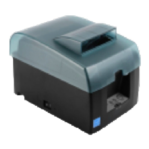
Star SP6000 SERIES User manual

DOT MATRIX PRINTER
SP6000 SERIES
Hardware Manual

< Approval: CEL >
Trademark acknowledgments
SP6000 : Star Micronics Co., Ltd.
Notice
•All rights reserved. Reproduction of any part of this manual in any form whatsoever, without STAR’s express
permission is forbidden.
•e contents of this manual are subject to change without notice.
•All eorts have been made to ensure the accuracy of the contents of this manual at the time of going to press.
However, should any errors be detected, STAR would greatly appreciate being informed of them.
•e above notwithstanding, STAR can assume no responsibility for any errors in this manual.
Copyright
©
2014 Star Micronics Co., Ltd..

TABLE OF CONTENTS
1. Unpacking and Installation......................................................................... 1
1-1. Unpacking ........................................................................................... 1
1-2. Notes about Installation....................................................................... 1
2. Parts Identication and Nomenclature....................................................... 2
3. Setup ............................................................................................................ 3
3-1. Connecting the Interface Cable to the PC............................................. 3
3-2. Connecting the Interface Cable to the Printer ...................................... 4
3-3. Connecting Power Cable ...................................................................... 5
3-4. Turning the Power On.......................................................................... 5
3-5. Ribbon Cartridge and Head Gap .......................................................... 6
3-6. Loading a Fanfold Paper ...................................................................... 8
3-7. Loading a Cut Sheet........................................................................... 11
3-8. Setup Precautions .............................................................................. 12
4. Control Panel............................................................................................. 13
4-1. Name of each part.............................................................................. 13
4-2. Features according to Panel Buttons................................................... 13
4-3. LED Indications................................................................................. 14
5. Maintenance............................................................................................... 15
6. External Specications .............................................................................. 16
-
1
-
1. Unpacking and Installation
* Accessories vary depending on the model and the
region where the printer was purchased.
1-1. Unpacking
Aer unpacking the unit, check that all the necessary accessories are included in the package.
1-2. Notes about Installation
1. Choose a rm, level surface where the printer will not be exposed to vibration.
2. Make sure that the printer is connected to a reliable power outlet. It should not be on the same electric circuit as copi-
ers, refrigerators, or other appliances that cause power spikes.
3. e power outlet you plan to connect to for power should be nearby and unobstructed.
4. Make sure that the printer is not exposed to direct sunlight.
5. Make sure that the printer is well away from heaters and other sources of extreme heat.
6. Do not locate the printer in a badly ventilated or dusty environment.
7. Make sure that the room where you are using the printer is not too humid.
8. Use the printer within the boundaries indicated in the environmental requirements. Even when the ambient tem-
perature and humidity are within the specications, avoid radical changes in environmental conditions. e suitable
operating temperature range is as follows:
Temperature Operating: 0°C to 35°C
Stand-by: -30°C to 65°C
Humidity Operating: 30% to 80%
Stand-by: 20% to 90%
9. When disposing of the printer, obey local regulations.
Printer
Holding plate
Safety Instructions
CD-ROM
Ribbon Cartridge

-
2
-
2. Parts Identication and Nomenclature
Printer cover
Open when loading paper or
the ribbon cartridge.
It is also used to reduce noise. Power switch
Turnstheprinteron
and o.
Paper guide plate
Feeds the paper horizon-
tally.
Control panel
Includesbuttonstooperatetheprinterand
lamps indicating the status of the printer.
(Refer to Section "4. Control Panel)
Rear cover
Open when loading paper. It is
also used to protect the printer
from dust and reduce noise.
Connects to the power
source via a cable.
Power connector
Connects to a host PC through
a cable.
Parallel interface connector
ConnectstoahostPCthrough
a cable.
USB interfaceconnector

-
3
-
3. Setup
3-1. Connecting the Interface Cable to the PC
3-1-1. Parallel Interface Cable
Connect the parallel cable to a parallel port on your PC.
3-1-2. USB Interface Cable
Connect the USB cable to a USB port on your PC.

-
4
-
3-2. Connecting the Interface Cable to the Printer
Printer cables are not included in the package.
Obtain an appropriate cable that complies with the specications beforehand.
Because the appropriate interface cable diers depending on the system that you are connecting the printer to, contact
the dealer that you bought the product from if you are unsure about what cable to use.
Note: Before connecting or disconnecting an interface cable, be sure to disconnect the power cable from the outlet.
3-2-1. Parallel Interface Cable
To connect a parallel cable, follow the procedure given below.
(1) Make sure that the power cable is not connected to the outlet.
(2) Connect the interface cable to the connector on the rear panel of the printer.
Fasten the connector clasps.
3-2-2. USB Cable
To connect a USB cable, follow the procedure given below.
(1) Make sure that the power cable is not connected to the outlet.
(2) Connect the USB cable to the USB port.
Parallel interface cable
USB cable

-
5
-
3-3. Connecting the Power Cable
Note: Before connecting or disconnecting the power cable, make sure that the printer and all the devices connected
to it are turned o.
(1) Connect the power cable to the connector on the printer.
Note: Use the power cable included with the printer.
(2) Insert the power cable plug into the outlet.
Note:• e included power cable is for exclusive use with this product.
Rated voltage: 100 – 240 V (Inlet type). Frequency: 50/60 Hz
• Takeintoconsiderationthenoiseintheenvironmentthattheprinterisinstalledin,andtakeappropriate
measures to protect the printer from static electricity, AC line noise, etc.
3-4. Turning the Power On
Connect the power cable according to the procedure in section 3-3, “Connecting the Power Cable”.
Turn on the power switch on the right side of the printer.
he POWER lamp on the control panel will ash. (No paper status)

-
6
-
3-5. Ribbon Cartridge and Head Gap
When loading the ribbon cartridge or setting the head gap, make sure that the power cable plug is disconnected from
the outlet.
3-5-1. Loading the Ribbon Cartridge
(1) Make sure that the power cable is not connected to the outlet.
(2) Remove the printer cover.
Hold the upper part of the head carriage and move it to the middle of the printer.
(3) Rotate the ribbon feed knob in the direction of the arrow until the ink ribbon becomes tight.
(4) Please install the ribbon cassette to the printer securely following the illustration shown below.
1
0
2
3
1
0
2
3
1
0
2
3
A
A
B
B
(NG)(OK)
Do not touch the print head immediately after printing because
it may still be hot. When loading the ribbon cartridge, move the
head carriage while holding its upper part.
Head carriage
Feed knob

-
7
-
(5) If the ink ribbon will not pass under the head easily, push in the ink ribbon using a thin object.
(6) Aer loading the ribbon cartridge, rotate the ribbon feed knob again in the direction of the arrow until the ink ribbon
becomes tight.
3-5-2. Setting the Head Gap
Referring to the table below, adjust the head gap according to the paper type and thickness..
Head Gap Position Paper Thickness (Total Thickness)
0 -
1(*10.06 to 0.12 mm
2 0.12 to 0.16 mm
3 0.16 to 0.20 mm
(*1: Head gap position 1 is the standard position.
Aer loading the ribbon cartridge or setting the head gap, attach the printer cover.
(NG)(OK)
1
0
2
3
1
0
2
3

-
8
-
3-6. Loading a Fanfold Paper
3-6-1. Paper Specications
Paper width 88.9 to 152.4 mm (3.5 to 6.0 inches)
Paper Length (One page) 76.2 to 558.8 mm (3.0 to 22 inches)
Paper thickness 0.07 to 0.20 mm (70 to 200 μm)
Copy Capability 3 sheets (Original + 2 copies)
3-6-2. Procedure
(1) Turn on the power switch of the printer.
(2) Referring to the gure below, remove the rear cover.
(3) Raising the tractor lever on the outside of the tractor allows the tractor to be moved.
If the tractor lever is lowered, the tractor’s position is xed.
First, move the le side tractor using the scale as a guide, and then lower the tractor lever to secure it.
Position for
left side of paper
Rear cover
Tractor
Tractor lever

-
9
-
(4) Open the tractors on the le and right side.
(5) Set the fanfold paper so that the sprockets match the sprocket holes on the paper, and then close the tractors.
(6) Adjust the position of the right side tractor, and then secure it.
(NG) (NG)(OK)
Sprocket holes
(Continuous paper)
Sprocket
(Tractor)

-
10
-
(7) Push the red circles in the gure below to attach the rear cover, paying attention to the attaching direction.
(8) Press the SET/EJECT button on the control panel to automatically set the paper to the start printing position.
For smooth feeding, it is recommended to place the continuous paper approximately 100 mm away from the printer.
Leave a gap of approximately 100 mm

-
11
-
3-7. Loading a Cut Sheet
(1) Turn on the power switch of the printer.
(2) Set the le side guide to match the size of the paper, and then insert the paper straight in the direction of the arrow
until it stops.
(3) e paper is automatically set to the start printing position.
Note: If cut paper is fed while fanfold paper is set on the tractors, the continuous paper will be released from the
tractors. To use fanfold paper again, reset it onto the tractors.
Position for left side of paper
[ Supported Paper ] 1 sheet
Paper width: 101.6 to 148.0 mm
Paper Length: 101.6 to 210.0 mm
Paper thickness: 0.07 to 0.18 mm
[ Supported Paper ] 1 sheet
Paper size:
A4 Portrait / A5 Landscape
Paper thickness: 0.07 to 0.18 mm

-
12
-
Caution Symbol
ese symbols are located near the print head.
Because the thermal print head is hot immediately aer printing, do not touch it.
is symbol is located near the screws securing the case or the protective plate, which
should not be opened by individuals other than service personnel. Individuals, other
than service personnel, should not remove these screws. High voltage areas in the case
can be dangerous.
WARNING
lIf you notice smoke or strange odors coming from this product, turn the power switch o immediately, and remove
the power cord from the AC outlet. For repairs, contact the dealer that you bought the product from.
lNever attempt to repair the product yourself. Doing so can be dangerous.
lNever disassemble or modify the product. Doing so may result in injury, re, or electric shock.
lDuring and immediately aer printing, the area around the print head is very hot. Don’t touch it because you could
be burned.
CAUTION
lWe recommend that you unplug the printer from the power outlet whenever you do not plan to use the printer for
long periods.
Because of this, you should locate the printer so that the power outlet it is plugged into is nearby and easy to access.
lIf an AC cord set is supplied with the product, the power cord that is included has been specially designed for the
product.
lMake sure that the printer and the PC are turned o and unplugged from their AC outlets before you make connec-
tions.
lDo not open the printer covers while the printer is printing or cutting.
lIf liquid or foreign objects (such as coins and paper) enter the inside of the printer, turn the power switch o,
disconnect the power cord from the AC outlet, and consult the dealer that you bought the product from.
Continuing to use the printer may lead to a short-circuit, which may cause electric shock or re.
lDo not operate the printer if there is moisture (which has been caused by condensation or another factor) on the
front surface of the head.
3-8. Setup Precautions

-
13
-
4-1. Name of each part
4-2. Features according to Panel Buttons
Refer to the following table.
e meanings of the symbols are as follows, ○: press the button, l: hold down the button. When both symbols are shown,
press the ○button while the lbutton is held down.
Printer status SET/EJECT
button
FEED
button
ONLINE
button Functions
ON-LINE ○Switches to o-line.
○Feeds paper to the cut position aer printing with continuous paper is
complete.
○Switches between high-speed and high-precision.
OFF-LINE ○Switches to on-line.
○Performs a line feed.
○Inserts/ejects continuous paper or ejects cut paper.
l○Feeds paper (page break).
○lFeeds paper slightly in the feeding direction.
○lFeeds paper slightly in the reverse direction.
○lChanges the auto loading position (see table below).
l○Sets the current paper position as the feeding position.
Power is turned
on while pressed lSelf-printing (Firmware version, Memory switch setting status)
lSelf-printing (Firmware version, Rolling ASCII <7 lines>, All ASCII
<Dra/Courier: 10 cpi, 12 cpi, proportional>, All kanji)
lHex dump mode: All signals sent from the host computer to the printer
are printed in hexadecimal code.
< During Auto Loading Position Change Mode >
SET/EJECT
button
FEED
button
ONLINE
button Functions
○lResets the feeding position to its factory default position, and then exits.
○lSaves the new feeding position, and then exits.
4. Control Panel
POWER lamp ONLINE lamp
SET/EJECT button ONLINE button
FEED button
MODE lamp

-
14
-
4-3. LED Indications
4-3-1. Normal status
If an error is detected, check the recovery conditions. Recovery is possible without changing the status of the printer.
Status POWER MODE ONLINE Recovery condition
Status ON
-
ON
-
Oine ON
-
OFF
-
High Quality Mode ON OFF
- -
High Speed Mode ON ON
- -
Paper Out Flashing 1 Sec.
-
OFF e printer recovers when you set a new paper roll
and close the cover.
Head high temperature
detection ON
-
Flashing 1 Sec. e printer recovers automatically when the ther-
mal head cools.
4-3-2. Error Indications
Turn o the printer, check the recovery conditions, and then turn on the printer again.
If the same error occurs aer restarting the printer, repairs are necessary.
Error description POWER MODE ONLINE Cause
Watchdog Timer
Flashing 0.5 Sec. OFF OFF Watchdog Timer time up
Mechanical Error Flashing 0.5 Sec. ON OFF Mechanical failure
Head ermistor error Flashing 0.5 Sec. OFF ON Head ermistor Detected Erroneous Value
PCB ermistor error Flashing 0.5 Sec. OFF Flashing 0.5 Sec. PCB ermistor Detected Erroneous Value
Power voltage down Flashing 0.5 Sec. Flashing 0.5 Sec. OFF ower Voltage Error Value Detected
FLASH Access Error Flashing 0.5 Sec. Flashing 0.5 Sec. Flashing 0.5 Sec. FLASH ROM Access Problem
RAM Access Error Flashing 0.5 Sec. Flashing 1 Sec. OFF RAM Access Problem
Firmware Error Flashing 0.5 Sec. Flashing 1 Sec. Flashing 1 Sec.
-
Note 1: If an unrecoverable error occurs, turn o the printer as quickly as possible.
2: If a power supply voltage error occurs, a power supply fault may be the cause of the error.
3:If paper is jammed, turn o the printer, remove the jammed paper, and then turn on the printer again.
If another type of unrecoverable error occurs, consult your dealer for repairs.

-
15
-
e printer may be adversely aected by paper dust or other types of dust.
To avoid trouble caused by dust, remove dust from inside the printer and keep each part well maintained.
Note: Make sure that the printer’s power switch is turned o when performing maintenance.
Clean the printer approximately once every 6 months or more oen when dust is visible.
Use a brush or small vacuum cleaner to remove the dust.
1
0
2
3
5. Maintenance

-
16
-
6. External Specications
External Dimensions: 275.0 mm (W) × 294.0 mm (D) × 163.0 mm(H)
Weight: Approx. 3.4 kg
14.0 54.0 240.0261.0
275.0
294.0
163.0
unit: mm

http://www.starmicronics.com/support/
Rev. 1.0
Table of contents
Other Star Printer manuals

Star
Star SP700 Series User manual

Star
Star SM-L200 SERIES User manual

Star
Star MP212FP-24-A Operating instructions

Star
Star TSP700 SERIES User manual

Star
Star SM-S401 User manual

Star
Star SM-S230I SERIES User manual

Star
Star futurePRNT TSP100IIU Manual

Star
Star LC-7211 User manual

Star
Star SP2000 Series Operating and maintenance manual

Star
Star StarPRNT mC-Print3 Series Manual

Star
Star HSP7000 User manual

Star
Star SM-S220 Series User manual

Star
Star TSP100III Series User manual

Star
Star SM-T300 User manual

Star
Star StarPRNT mC-Print3 Series User manual

Star
Star NX-2480 User manual

Star
Star SM-S400 Quick start guide

Star
Star LC-4522 User manual

Star
Star HSP7000 User manual

Star
Star TSP100IIIBI Quick start guide