manuals.online logo
Brands
  1. Home
  2. •
  3. Brands
  4. •
  5. Status Instruments
  6. •
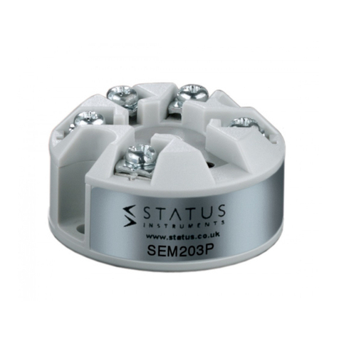
  7. Transmitter
  8. •
  9. Status Instruments SEM110 User manual

Status Instruments SEM110 User manual

D2133_01_04 CN5082 SEM110 User Guide
1.0 GENERAL
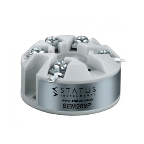
The SEM110 series are high performance two wire (4 to 20) mA
transmitters designed to accept most standard industrial temperature,
thermocouple, slide wire and variable resistance sensors which operate
over most common ranges. Automatic thermocouple cold junction
compensation is provided on thermocouple versions where the output is
directly referenced to the mV input, allowing linearisation to be carried out
by the loop monitoring instrumentation, if required. The device is potted
inside a plastic enclosure, suitable for head mounting into any DIN style
enclosure. Screw terminals are provided for wire connections. Trim
potentiometers are provided to allow calibration adjustments.
2.0 SEM110 SPECIFICATION @ 20 ºC
Part Number Input Type
SEM110TC Isolated (Un-grounded) Thermocouple types
K,T,J,R,S,N
SEM110P PT100, PT10, PT1000
SEM110W Slide Wire
SEM110Z Variable resistance
SEM110D Differential PT100
OUTPUT (4 to 20) mA two wire (Max 30 mA)
SUPPLY VOLTAGE (10 to 45) V DC reverse connection protected.
30 VDC Max I.S. version
AMBIENT TEMP (0 to 70) ºC operation
(-40 to 100) ºC storage
AMBIENT HUMIDITY (0 to 95) % (non condensing)
CONNECTION Screw Terminal
Recommended cable size 2.5 mm sq.
ZERO DRIFT ±2 µA/ºC
SPAN DRIFT ±0.01 %/ºC
LOOP RESISTANCE 700 R Max (24 V)
EMC Conforms to BS EN 61326
3.0 INSTALLATION
3.1 Mechanical
The transmitter is mounted using two 4.5 mm diameter holes, on standard
33 mm fixing centres. This transmitter has been specifically designed to
be mounted inside a DIN standard probe head, which must provide
adequate protection to moisture, corrosive atmospheres etc. All cable
entries should be sealed using the correct size cable gland.
Care must be taken when locating the transmitter to ensure the ambient
temperature remains inside the specified range of (0 to 70) ºC. The
diagram shows the mechanical layout with a typical application of the
transmitter mounted inside a probe head enclosure.
Mounting Holes: 2 Holes 4.5 mm Diameter, 33 mm Centres
3.2 Electrical
Connections to the transmitter are made to the screw terminals provided
on the top face.
The SEM110 conforms to BS EN 61326 and as such, the radiated
electromagnetic susceptibility is tested to 3 v/m. It is therefore recommend
that during the installation process, the instrument should be mounted
away from any high powered radio transmitters and away from any heavy
switching gear.
To maintain EMC compliance input/sensor wires must be less than 3
metres long and output wiring must use screened twisted pair cable with
the screen earthed at one end only.
All three input wires must have the same core diameter to maintain equal
lead resistance in each wire. T/C sensors must be ungrounded.
The transmitter is protected against reverse connection by means of a
series diode, therefore incorrect connection of the output wires will result in
near zero current flow in the loop. Incorrect connection or failure of the
sensor wires will result in the transmitter saturating, T/C versions go
upscale, whilst resistance sensor inputs go either upscale or downscale
dependant upon which wire breaks. The most common failure would be a
total sensor burnout, in which case the
transmitter will go upscale.
3.3 connections
Pt 100, 3 Wire
Only TC with Isolated Junction
Type D, Differential Temperature
Type W, Slide wire
Type Z, Variable Resistor
The diagram shows the method of connection to provide a (4 to 20) mA
current loop output.
SEM110
TEMPERATURE TRANSMITTER
Designed, manufactured and supported by:
Status Business Park, Gannaway Lane
Tewkesbury Glos. GL20 8FD. UK
Tel: +44 (0)1684 296818 Fax: +44 (0)1684 293746
Email: [email protected]
Every effort has been taken to ensure the accuracy of this specification, however we do
not accept responsibility for damage, injury, loss or expense resulting from errors and
omissions, and we reserve the right of amendment without notice
LOAD
POWER
(24V NOM)
SUPPLY
-
+
Ra-Rb
Rb
Ra
20mA
4mA
3 2 . 0 1 .8
5 3 . 0
Z e ro
S p a n
D2133_01_04 CN5082 SEM110 User Guide
The Pt100 sensor shown as an example would normally take the form of a
probe assembly with a three wire output. Refer to connection drawing for
other connection types. The output loop shows a 24 V DC power supply
used to provide loop excitation, the transmitter and a load all connected in
series. The load symbol represents other equipment in the loop e.g.
indicators, controllers, loggers etc. Sometimes these instruments come
with the 24 V supply built in as standard, this simplifies wiring and reduces
cost. Care must be taken when designing the (4 to 20) mA circuit to
ensure that the total burden of the loop, that is the total voltage
requirements of all the equipment in the loop added together, does not
exceed the power supply voltage. If a number of instruments are
connected in the loop, ensure that only one instrument is tied to ground.
Grounding the loop at two points will result in shorting out part of the loop
and therefore any instruments in that part of the loop will not operate.
4.0 Calibration
Calibration is only recommended when the user has access to suitable
equipment, together with a reasonable knowledge of instrumentation
calibration techniques. The following instructions act as a guideline to
calibration.
4.1 A precision calibrator will be required, to simulate the type of
sensor the transmitter is designed for, together with a set of
tables giving the sensor output against process variable, (e.g.
resistance against temperature for a PT100 sensor). A
precision digital current meter together with a 24 V DC supply
will also be needed. Read the SEM110 label to establish the
transmitter range i.e. the process variable input for 4 mA and
20 mA. The side label also indicates the location of the span
and zero pots.
4.2 Connect calibrator to input terminals, using the correct
compensation wire for thermocouples inputs and three wire
connection for RTD inputs. Connect the output positive to +24
V, negative to 0 V via current meter. Turn power on.
4.3 Set simulator to 4 mA process variable and adjust ZERO
trimmer for 4.000 mA output. ±0.002mA
4.4 Set simulator to 20 mA process variable and adjust SPAN
trimmer for 20.000 mA output ±0.002 mA.
4.5 Repeat steps 4.3 and 4.4 until both points are in calibration.
4.6 Turn power off and remove calibration equipment.
5.0 SEM110X\* VERSIONS - FOR USE IN POTENTIALLY EXPLOSIVE
ATMOSPHERES
5.1 ATEX Certificate
The SEM110X/* models has been issued with a EC-type examination
certificate, confirming compliance with the European ATEX directive
94/9/EC for :-
Intrinsic safety II 1 G EEx ia IIC T5.
The equipment bears the Community Mark and subject to local codes of
practice, may be installed in any of the European Economic Area (EEA)
member countries. The SEM110X housing is coloured light blue to identify
the equipment as suitable for Hazardous area use. The equipment must
be installed and maintained in accordance with local requirements for
electrical equipment for use in potentially explosive atmospheres, eg
EN60079-14 & EN60079-17. This instruction sheet describes installation
which conforms with BS EN60079-14 & BS EN60079-17 Electrical
Installation in Hazardous Areas. When designing systems outside the UK,
the local Code of Practice should be consulted.
5.2 Atex marking
Common Information
Manufacturer Status Instruments Ltd
Type Number SEM110X/P
SEM110X/TC
SEM110X/W
CE Marking 0891
Explosive Protection Marking
(Type ia) Intrinsic Safety
II 1 Equipment Group and category
G Type of explosive atmosphere (Gas)
EEx ia IIC T5 Intrinsic safety information
TRL03ATEX21004X Certificate reference
5.3 Special Conditions for Safe Use
As indicated by the Certificate Reference "X" suffix, special conditions
apply for safe use for both intrinsic safety and energy limitation
applications. They are as follows:-
5.4 Zones, Gas Groups, and T rating.
When connected to a approved system the SEM110X/* may be installed
in:-
Zone 0 explosive gas air mixture continuously present
Zone 1 explosive gas air mixture likely to occur in normal use
Zone 2 explosive gas air mixture not likely to occur and if it does, it will
only occur for a short time.
Be used in gas groups;-
Group A propane
Group B ethylene
Group C hydrogen
Allowable Temperature classification / ambient temperature:-
Intrinsic safety (Type ia)
Class
T5 100°C : Ta = -20°C to +40°C
T4 135°C : Ta = -25°C to +55°C
T3 200°C : Ta = -25°C to +55°C
T2 300°C : Ta = -25°C to +55°C
T1 450°C : Ta = -25°C to +55°C
5.5 Environmental Protection
This equipment must be housed in an enclosure which provides a degree
of protection of at least IP54. The enclosure must be suitable for the
atmosphere and environment in which it is installed (eg If of plastic
material, must be resistant to chemical corrosion, UV light, temperature,
humidity etc.)
5.6 Maintenance
This intrinsically safe equipment contains no user serviceable, adjustable
or replaceable parts. No attempt should be made to repair a faulty
SEM110X/* transmitter, all units must be returned to the manufacture for
repair or replacement. Attempt service or replacement of parts may
invalidate the explosive protection features of the equipment.
5.7 Connection Diagram
They equipment must be electrically connected as shown below:-
SEM110X\* Working Parameters
Ui 28 V
I i 93.3 mA
Pi 0.653 W
Ci 0 nF
Li 0 uH
-
SE M110XCALIBRAT O R
D C
+ - +24V
A
SENSOR
SEM110X
3 1
4
5
2
BARRIER
Maximum
output
Vo 30V
Io 100mA
Po 750mW
DC
SUPPLY
+
-

Other Status Instruments Transmitter manuals

Status Instruments SEM310 User manual

Status Instruments

Status Instruments SEM310 User manual

Status Instruments SEM210 User manual

Status Instruments

Status Instruments SEM210 User manual

Status Instruments SEM1603TC User manual

Status Instruments

Status Instruments SEM1603TC User manual

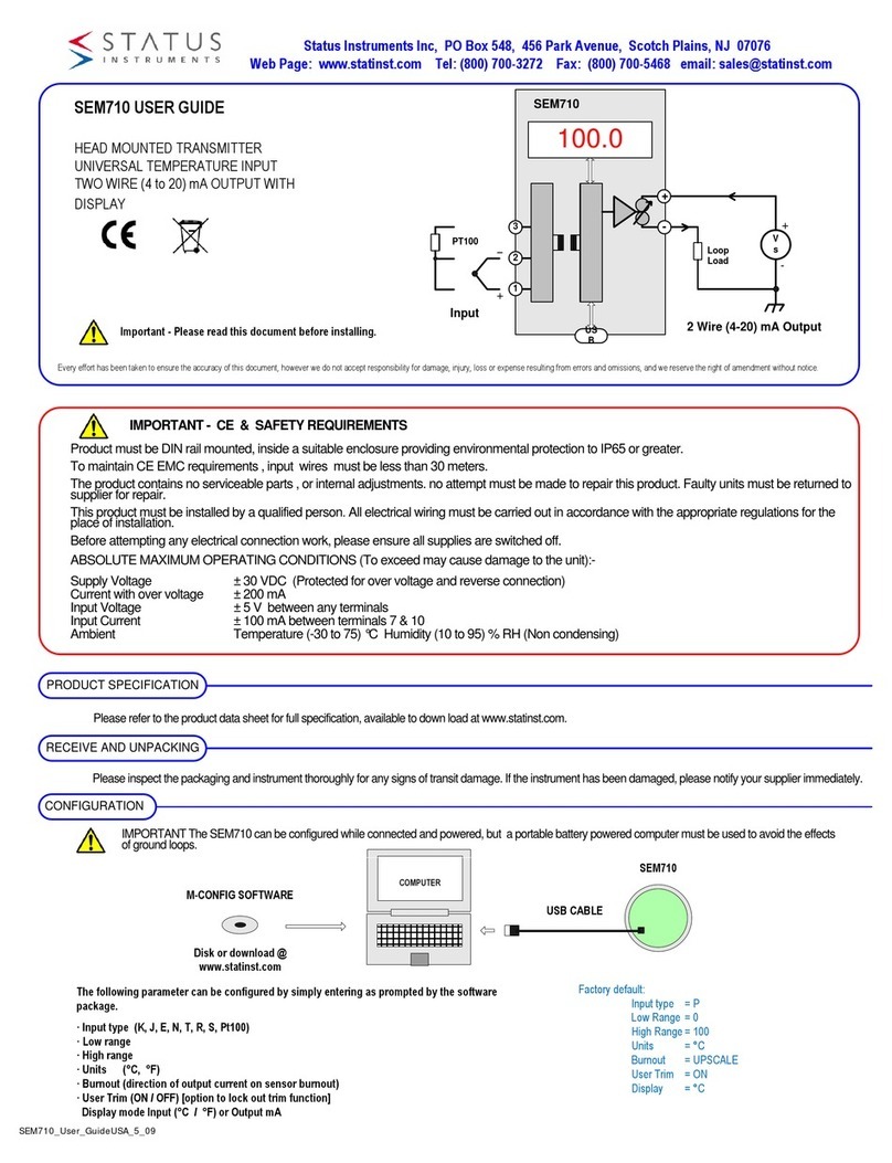
Status Instruments SEM710 User manual

Status Instruments

Status Instruments SEM710 User manual

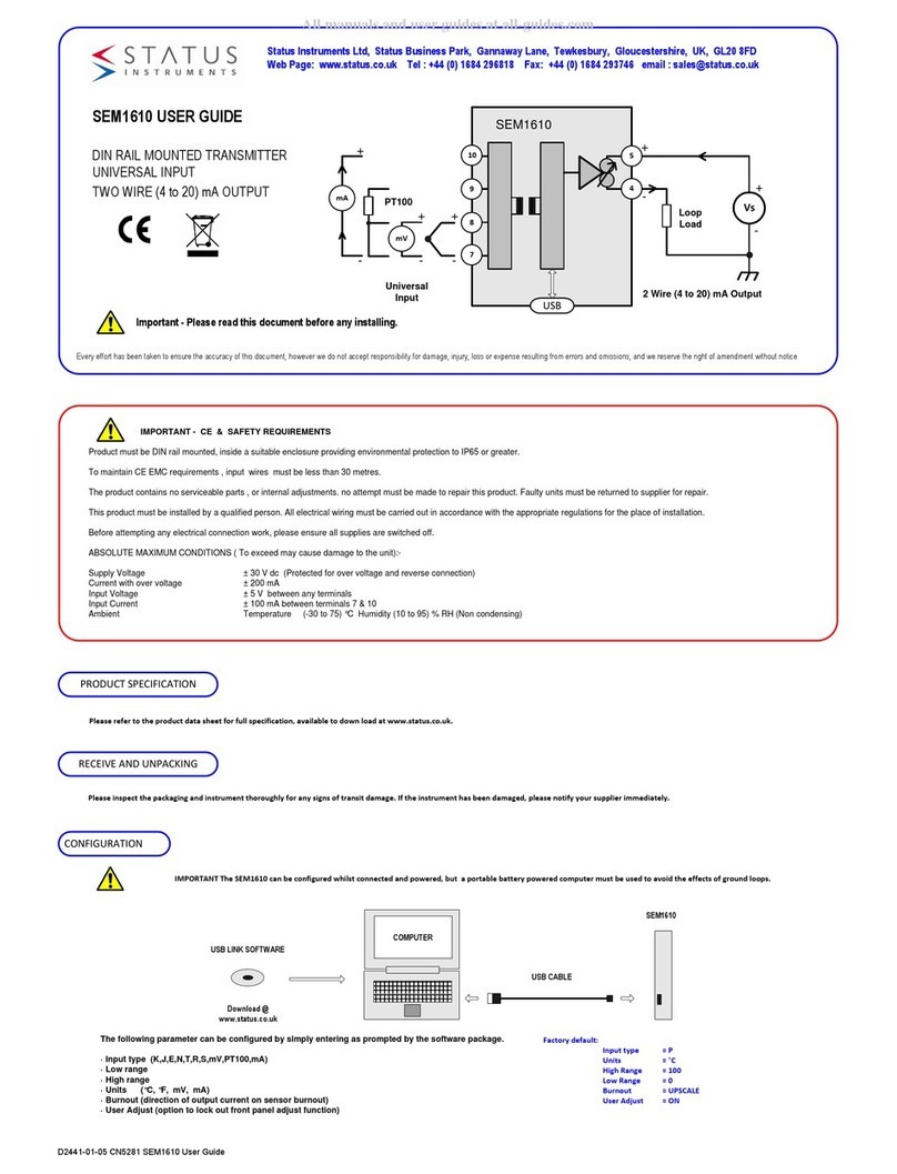
Status Instruments SEM1610 User manual

Status Instruments

Status Instruments SEM1610 User manual

Status Instruments SEM1605/P User manual

Status Instruments

Status Instruments SEM1605/P User manual

Status Instruments WTX700 Series User manual

Status Instruments

Status Instruments WTX700 Series User manual

Status Instruments SEM310 User manual

Status Instruments

Status Instruments SEM310 User manual

Status Instruments SEM206/P User manual

Status Instruments

Status Instruments SEM206/P User manual

Status Instruments SEM210X Installation instructions

Status Instruments

Status Instruments SEM210X Installation instructions

Status Instruments SEM203P MKII User manual

Status Instruments

Status Instruments SEM203P MKII User manual

Status Instruments SEM523P User manual

Status Instruments

Status Instruments SEM523P User manual

Status Instruments SEM203/TC User manual

Status Instruments

Status Instruments SEM203/TC User manual

Status Instruments SEM1610 User manual

Status Instruments

Status Instruments SEM1610 User manual

Popular Transmitter manuals by other brands

Superior Broadcast SBFM100-SS user manual

Superior Broadcast

Superior Broadcast SBFM100-SS user manual

Argos E0207TR-2 user manual

Argos

Argos E0207TR-2 user manual

Monacor JTS PT-920BG/5 instruction manual

Monacor

Monacor JTS PT-920BG/5 instruction manual

WAREMA EWFS Operating and installation instructions

WAREMA

WAREMA EWFS Operating and installation instructions

Audiovox Prestige APS-2K4MS Programming guide

Audiovox

Audiovox Prestige APS-2K4MS Programming guide

BWI Eagle AIR-EAGLE SR PLUS Product information bulletin

BWI Eagle

BWI Eagle AIR-EAGLE SR PLUS Product information bulletin

Novatech CONTROLS 1738 Technical manual

Novatech CONTROLS

Novatech CONTROLS 1738 Technical manual

scope Connexions CX6USA Installation & user manual

scope

scope Connexions CX6USA Installation & user manual

B&C WGATX1 user manual

B&C

B&C WGATX1 user manual

R.V.R. Electronica AUD2MP1 user manual

R.V.R. Electronica

R.V.R. Electronica AUD2MP1 user manual

CYP PU-507TX-CVGA Operation manuals

CYP

CYP PU-507TX-CVGA Operation manuals

SMAR TT 400 SIS Owner's operation and maintenance manual

SMAR

SMAR TT 400 SIS Owner's operation and maintenance manual

Ahlborn ALMEMO 8390-1 Operating	 instruction

Ahlborn

Ahlborn ALMEMO 8390-1 Operating instruction

M-system W2VS instruction manual

M-system

M-system W2VS instruction manual

blukii Smart Key Go Mini manual

blukii

blukii Smart Key Go Mini manual

Cadi SmartSense SmartTAG STG-821W user manual

Cadi

Cadi SmartSense SmartTAG STG-821W user manual

GF Signet 9950 operating instructions

GF

GF Signet 9950 operating instructions

blukii Smart Key Go 500 manual

blukii

blukii Smart Key Go 500 manual

manuals.online logo
manuals.online logoBrands
  • About & Mission
  • Contact us
  • Privacy Policy
  • Terms and Conditions

Copyright 2025 Manuals.Online. All Rights Reserved.