manuals.online logo
Brands
  1. Home
  2. •
  3. Brands
  4. •
  5. Staubli
  6. •
  7. Cables And Connectors
  8. •
  9. Staubli CombiTac uniq CT-GOF User manual

Staubli CombiTac uniq CT-GOF User manual

1 / 4
MA000 (de_en)
Montageanleitung
MA000 (de_en)
Assembly instructions
MA213-06 (fr_en)
Notice de montage
MA213-06 (fr_en)
Assembly instructions
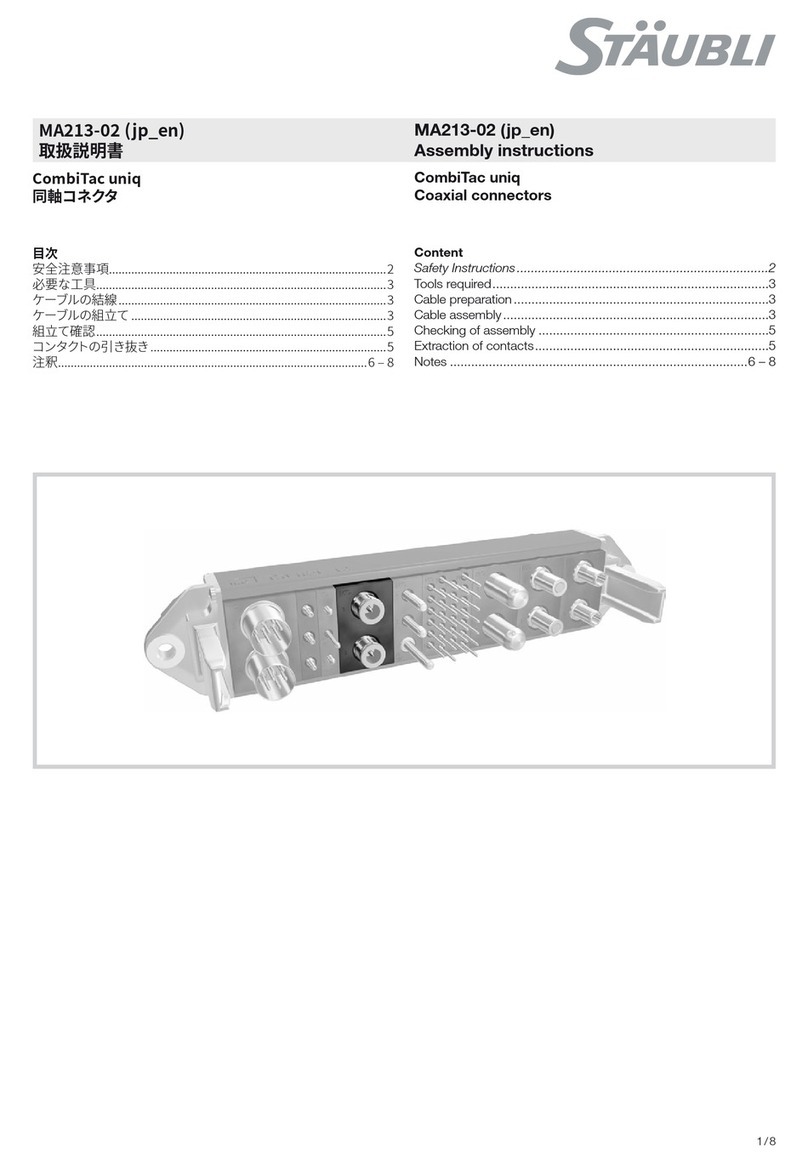
CombiTac uniq
bre optique en verre CT-GOF
CombiTac uniq
Glass Optical Fibre CT-GOF
Sommaire
Consignes de sécurité ����������������������������������������������������������������2
Montage ������������������������������������������������������������������������������������3
Démontage��������������������������������������������������������������������������������4
Capuchons de protection ����������������������������������������������������������4
Content
Safety Instructions����������������������������������������������������������������������2
Assembly�����������������������������������������������������������������������������������3
Disassembly ������������������������������������������������������������������������������4
Protective caps ��������������������������������������������������������������������������4
2 / 4
Consignes de sécurité Safety instructions
Le montage et l’installation des produits ne doivent être ef-
fectués que par du personnel qualié et formé en respectant
toutes les dispositions de sécurité et réglementations légales
applicables�
Stäubli Electrical Connectors (Stäubli) décline toute responsa-
bilité en cas de non-respect de ces consignes�
The products may be assembled and installed exclusively by
suitably qualied and trained specialists duly observing all ap-
plicable safety regulations�
Stäubli Electrical Connectors (Stäubli) does not accept any li-
ability in the event of failure to observe these warnings�
Utiliser uniquement les pièces et outils recommandés par
Stäubli� Suivre scrupuleusement les étapes de préparation et
de montage décrites ici, faute de quoi ni la sécurité ni le res-
pect des caractéristiques techniques ne sont garantis� Ne pas
modier le produit d’une quelconque manière.
Use only the components and tools specied by Stäubli. In
case of self-assembly, do not deviate from the preparation and
assembly instructions as stated herein, otherwise Stäubli can-
not give any guarantee as to safety or conformity with the
technical data� Do not modify the product in any way�
Les connecteurs non fabriqués par Stäubli qui sont enchables
avec des éléments Stäubli, et parfois qualiés de «compatibles
Stäubli» par les fabricants, ne répondent pas aux exigences
d’une liaison électrique sûre et stable à long terme. Ils ne
doivent pas, pour des raisons de sécurité, être enchés dans
des éléments Stäubli� Nous déclinons par conséquent toute
responsabilité si ces connecteurs non approuvés par Stäubli
sont utilisés avec des éléments Stäubli et qu’il en résulte des
dommages�
Connectors not originally manufactured by Stäubli which can
be mated with Stäubli elements and in some cases are even
described as ”Stäubli-compatible” by certain manufacturers
do not conform to the requirements for safe electrical connec-
tion with long-term stability, and for safety reasons must not
be plugged together with Stäubli elements� Stäubli therefore
does not accept any liability for any damages resulting from
mating such connectors (i�e� lacking Stäubli approval) with
Stäubli elements�
Les travaux décrits ici ne doivent pas être effectués
sur des parties parcourues par un courant ou sous
tension.
The work described here must not be carried out
on live or load-carrying parts.
La protection contre les chocs électriques doit être
assurée par le produit nal et garantie par l’utili-
sateur.
Protection from electric shock must be assured by
the end product (i.e. by the correctly assembled
plug connector) and by its user.
Les connecteurs ne doivent pas être débranchés
sous charge. L’embrochage et le débrochage sous
tension sont permis.
The plug connections must not be disconnected
under load. Plugging and unplugging when live is
permitted.
Avant chaque utilisation, il conviendra de vérier
visuellement (en particulier l‘isolation) l‘absence de
tout défaut externe. En cas de doute concernant
la sécurité du matériel, il conviendra de faire appel
à un expert ou de procéder au remplacement du
connecteur incriminé.
Each time the connector is used, it should previously
be inspected for external defects (particularly in the
insulation). If there are any doubts as to its safety, a
specialist must be consulted or the connector must
be replaced.
Les connecteurs dans le boîtier sont protégés contre
l‘eau conformément au degré de protection IP indi-
qué pour le produit.
The plug connectors in the housing are protected
from water in accordance with the IP protection
class stated for the relevant product.
Les connecteurs non branchés doivent être protégés
contre l’humidité et la saleté. Il est interdit d’embro-
cher des connecteurs encrassés.
Unmated plug connectors must be protected from
moisture and dirt. The male and female parts must
not be plugged together when soiled.
Pour des caractéristiques techniques détaillées, se
reporter au catalogue des produits.
For further technical data please see the product
catalogue.
Explication des symboles Explanation of the symbols
Mise en garde contre une tension électrique dan-
gereuse Warning of dangerous voltages
Mise en garde contre un danger Warning of a hazard area
Remarque ou conseil utile Useful hint or tip
3 / 43 / 4
1
2
3
Montage Assembly
Remarque:
La confection des contacts de
bres optiques doit être effectuée
par du personnel spécialisé avec un
équipement approprié. Pour le sertis-
sage du manchon de xation, il est
recommandé d’utiliser une pince à
sertir à matrice hexagonale et ouver-
ture de clé de 3.3mm.
Note:
The assembly of glass bre con-
tacts must be carried out by special-
ised personnel with the appropriate
equipment. For crimping the reten-
tion sleeve, a crimping tool with a
hexagonal form and a wrench size of
3.3mm is recommended..
(ill. 1)
Introduire les câbles confectionnés
latéralement dans la plaque-support�
Ramener les câbles en arrière jusqu’à
ce que les contacts soient en appui
dans la plaque-support�
(ill. 1)
Insert assembled cable laterally into
the holding plate�
Pull back cable until contacts are posi-
tioned in the holding plate�
(ill. 2)
Pousser les contacts avec la plaque-
support dans le corps isolant, veiller à
un positionnement correct (1-4)�
(ill. 2)
Push contacts into the contact carrier
with the holding plate�
Make sure that they are correctly
positioned� (1-4)
(ill. 3)
Pousser la plaque-support vers le
corps isolant jusqu’à ce que les pattes
d’arrêt s’enclenchent de manière
audible�
(ill. 3)
Press holding plate towards the con-
tact carrier until retaining latches have
both engaged audibly�
Attention
Contrôler la position!
Attention
Check correct position!
4 / 44 / 4
7
4
6
S
8
S
5
Fabricant/Producer:
Stäubli Electrical Connectors AG
Stockbrunnenrain 8
4123 Allschwil/Switzerland
Tél. +41 61 306 55 55
Fax +41 61 306 55 56
mail [email protected]
www.staubli.com/electrical
© by Stäubli Electrical Connectors AG, Switzerland – MA213-06 – 01.2017, Index a, Marketing Communications – Sous réserve de modications / Subject to alterations
Démontage Disassembly
(ill. 4)
Plier légèrement la patte d’arrêt vers
l’extérieur� Selon la position de monta-
ge, on pourra s’aider d’un tournevis�
(ill. 4)
Bend the retaining latch slightly out-
wards� Depending on the installation
position, a screwdriver may be used�
(ill. 5)
Depuis le côté d’embrochage, exercer
une pression sur les contacts jusqu’à
ce que la plaque-support soit dé-
verouillée� Répéter l’opération sur la
deuxième patte d’arrêt�
(ill. 5)
From the plugging side, exert pressure
on the contacts until the holding plate
is pushed out of the retention� Repeat
operation on the second retaining
latch�
(ill. 6)
Extraire la plaque-support avec les
contacts du corps isolant� Dans le cas
de contacts mâles, il est recommandé
d’exercer la pression sur les contacts
avec un contact femelle non-câblé.
Cela permet d’exercer une pression
plus élevée et protège la surface ter-
minale des bres contre l’endomma-
gement et l’encrassement�
(ill. 6)
Pull holding plate out of the contact
carrier with the contacts� When deal-
ing with pin contacts, it is recom-
mended to exert pressure on the
contacts with an unassembled socket
contact� This enables greater pressure
to be exerted and protects the end
surface of the bres from damage and
dirt�
Capuchons de protection Protective caps
Contacts pré-assemblés avec ca-
puchons de protection (ill. 7-8)
Pre-assembled contacts with pro-
tective caps (ill. 7-8)
Attention
Enlever tous les capuchons de
protection (S) avant la connexion�
Attention
Before plugging, remove all the
protective caps (S)�

Other Staubli Cables And Connectors manuals

Staubli KBT21BV-GS Series User manual

Staubli

Staubli KBT21BV-GS Series User manual

Staubli MPC3-BS User manual

Staubli

Staubli MPC3-BS User manual

Staubli CombiTac uniq POF contacts User manual

Staubli

Staubli CombiTac uniq POF contacts User manual

Staubli PV-KST4 UR Series User manual

Staubli

Staubli PV-KST4 UR Series User manual

Staubli PV-KST4 UR Series User manual

Staubli

Staubli PV-KST4 UR Series User manual

Staubli KST10BV-AX/M C Series User manual

Staubli

Staubli KST10BV-AX/M C Series User manual

Staubli CombiTac MA213-09 User manual

Staubli

Staubli CombiTac MA213-09 User manual

Staubli PV-AZS4 User manual

Staubli

Staubli PV-AZS4 User manual

Staubli MA417-1 User manual

Staubli

Staubli MA417-1 User manual

Staubli PV-BVK4 User manual

Staubli

Staubli PV-BVK4 User manual

Staubli 16BL-PP User manual

Staubli

Staubli 16BL-PP User manual

Staubli PV-AZS4 User manual

Staubli

Staubli PV-AZS4 User manual

Staubli PV-ADB4-EVO 2 UR Series User manual

Staubli

Staubli PV-ADB4-EVO 2 UR Series User manual

Staubli SMK425-L User manual

Staubli

Staubli SMK425-L User manual

Staubli MA231 User manual

Staubli

Staubli MA231 User manual

Staubli Multi-Contact SLS410-BK User manual

Staubli

Staubli Multi-Contact SLS410-BK User manual

Staubli MA169 User manual

Staubli

Staubli MA169 User manual

Staubli MC PV-KBT3/IV User manual

Staubli

Staubli MC PV-KBT3/IV User manual

Staubli CombiTac direqt User manual

Staubli

Staubli CombiTac direqt User manual

Staubli PV-KBT4-EVO ST Series User manual

Staubli

Staubli PV-KBT4-EVO ST Series User manual

Staubli 16BL-CP User manual

Staubli

Staubli 16BL-CP User manual

Staubli RobiFix User manual

Staubli

Staubli RobiFix User manual

Staubli CombiTac uniq CT-GOF User manual

Staubli

Staubli CombiTac uniq CT-GOF User manual

Staubli CombiTac MA213-06 User manual

Staubli

Staubli CombiTac MA213-06 User manual

Popular Cables And Connectors manuals by other brands

Philips SWV7166W Specifications

Philips

Philips SWV7166W Specifications

Eaton ZB4-209-DS2 Instruction leaflet

Eaton

Eaton ZB4-209-DS2 Instruction leaflet

DVIGear DVI-26xxx-AOC quick start guide

DVIGear

DVIGear DVI-26xxx-AOC quick start guide

Avermedia EzRecorder 130 user manual

Avermedia

Avermedia EzRecorder 130 user manual

Marechal Electric MELTRIC CS1000 operating instructions

Marechal Electric

Marechal Electric MELTRIC CS1000 operating instructions

ZHONGTIAN GPF-01 Operation manual

ZHONGTIAN

ZHONGTIAN GPF-01 Operation manual

OMB TVS-TUNNEL/S quick start guide

OMB

OMB TVS-TUNNEL/S quick start guide

Philips Sonicare 300 SerieS user manual

Philips

Philips Sonicare 300 SerieS user manual

Philips Sonicare 300 SerieS Information

Philips

Philips Sonicare 300 SerieS Information

Leviton J1772 installation instructions

Leviton

Leviton J1772 installation instructions

Thitronik XL 868 quick guide

Thitronik

Thitronik XL 868 quick guide

Xo NB-Q233A user manual

Xo

Xo NB-Q233A user manual

Lightolier Lytespan "T instructions

Lightolier

Lightolier Lytespan "T instructions

jbc 0014848 manual

jbc

jbc 0014848 manual

Artistic Licence Rail-Split extreme user guide

Artistic Licence

Artistic Licence Rail-Split extreme user guide

RTW 1161 Mounting manual

RTW

RTW 1161 Mounting manual

HEIDENHAIN ROD 420 TTL Mounting instructions

HEIDENHAIN

HEIDENHAIN ROD 420 TTL Mounting instructions

Festo VAVE-L1 Series Assembly instructions

Festo

Festo VAVE-L1 Series Assembly instructions

manuals.online logo
manuals.online logoBrands
  • About & Mission
  • Contact us
  • Privacy Policy
  • Terms and Conditions

Copyright 2025 Manuals.Online. All Rights Reserved.